


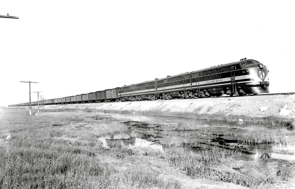
Diesel-electric locomotive technology has advanced significantly since World War II. Experience leads me to list these eight technological breakthroughs as the most important in the postwar period. Important technology developments preceded World War II, but we began with the era after General Motors’ Electro-Motive Division introduced “The Diesel that Did It,” the FT [see “FT … the diesel that did it,” May 1965]. This cab unit stormed U.S. railroads, demonstrating the value of diesel-electric locomotives. The FT set performance standards as technology stabilized around a platform of electromechanical systems, changing the way railroads operated for decades.
Listed chronologically, these eight breakthroughs span 50 years. They do not include diesel engine advances, as those easily fill another article. Some of the breakthroughs discussed are no longer pertinent today, but played a critical role in advancing locomotive technology.
Diesel-electric locomotives find their origin in streetcars. By 1900, lightweight vehicles with two-axle trucks, wooden carbodies, little heat, and no air conditioning were trundling along many urban streets powered from above by direct current. A decade later, their big cousins — the interurban cars — emerged, connecting urban areas. Interurbans owned their own rights-of-way, and often traveled at frightening speeds, but were early casualties of the automobile. Streetcars and interurbans shared technology. They both used spring-loaded pantographs, whose carbon brushes grabbed 600-volt DC power from above, sending electricity to axle-mounted traction motors. Their series-wound shunt motors were ideal for variable speed control from an eight-position rheostat. Early on, the goal became to say goodbye to overhead wires and take the power-generating source along aboard the passenger vehicle.
No. 1: Automatic Transition
Automatic transition for diesel-electric or electric locomotives is analogous to an automatic transmission for highway vehicles. Why don’t locomotives have mechanical transmissions? A transmission is necessary to reduce the high rotational speed of the diesel engine to the low speed, high torque of locomotive drive wheels. Mechanical transmissions lack the flexibility and durability needed for North American road locomotives. A hydraulic coupling of the diesel engine and drive wheels is possible and was briefly used in the 1960s on locomotives imported by the Southern Pacific and Denver & Rio Grande Western. This arrangement lacked flexibility and incurred high maintenance costs.
An electrical coupling — an electric generator (later alternators) connected directly to the diesel engine crankshaft — is practical. Such rotating equipment provides the current for electric motors geared to the driving axles. Thus, we have on-board power generation replacing overhead wires supplying electrical power to a true electric locomotive.
One more step is necessary to make this work: transition. When the armatures of DC motors rotate, they create counter or back electro-motive force that bucks the applied generator voltage. Back EMF is a function of motor design and rotational speed. The faster the locomotive goes, the more back EMF traction motors create. At some point, the back EMF becomes great enough that, when combined with armature resistance, the locomotive cannot accelerate further. This can be overcome with more generator voltage; however, a rotating generator has its limitations. There is another solution, requiring changes in the traction motor power circuit. Since each traction motor has a certain amount of inherent resistance, the power circuit can be rearranged to diminish resistance. When the traction motors are placed in series, each motor experiences the most current and offers the highest resistance. When placed in parallel, the total motor set resistance is cut dramatically, and a reduced amount of current is available for each motor. Between the initial series circuit and subsequent parallel power circuits, there is an intermediate step. The motors can be arranged in a circuit that is partially in series and partially parallel, called series-parallel, which provides a more modest drop in resistance without as large a reduction in available current.
The concept works because DC-series shunt motors excel at producing low-rotational-speed torque but require much current to do so. On the other hand, DC service shunt motors at high rotational speeds need more applied voltage to keep turning, but not nearly as much current. The characteristics of DC-series shunt motors fit perfectly with freight locomotive requirements.
In the early days, operators had to manually throw a transition lever, once, twice, or three times at prescribed speeds, to effect the circuit change, gaining the necessary acceleration. The reverse was also true. Early diesel-electric locomotive engineers had to move a transition lever to actuate “backward” transition when slowing down — like downshifting in a manual-transmission truck. In extreme cases, the engineer moved the brake handle, throttle, and transition lever, all in short order. Hence, EMD engineers came up with an automatic transition.
For any DC traction motor, whether the locomotive utilizes four or six motors, the point at which transition becomes necessary is definable in terms of current (amps) and voltage. The EMD solution used current transducers and voltage readings to pick up relays at defined levels. In turn, these activated power contactors (large, electrically controlled power switches) to reconfigure the traction motor power circuit arrangement. Another version of combatting back EMF involved placing resistors in parallel with the field coils of each traction motor. In some designs, many steps of changing the amount of parallel resistance were included. Eventually, the output of larger traction alternators, and the introduction of AC motors, made transition unnecessary.
No. 2: Dynamic Brake
Dynamic braking utilizes the traction motors as generators retarding forward motion. For rotating electrical equipment — motors — there are two inputs and one output. For a motor, the inputs are power to the armature and field coils. The output is rotational torque. As a DC generator, the same machine receives inputs of power to the field coils and rotational torque to the armature, resulting in an output of electrical energy.
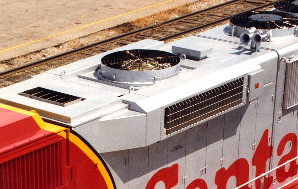
In the early days of diesel-electric locomotives, dynamic brakes were viewed by some railroads as an unnecessary, expensive option. Dynamic brakes added about 40% to the electrical circuits of pre-microprocessor locomotives. Additionally, the large resistors (called grids), used to dissipate the electrical energy as heat, slowly deteriorate with use. Illinois Central, with flat terrain, was inclined to use George Westinghouse’s traditional automatic air brakes. On the other hand, a mountainous railroad like Norfolk & Western saw wisdom in the dynamic brake and ordered this option on its first diesel units. Doubtless, dynamic braking on mountainous terrain has aided operations and prevented accidents.
After the conversion to diesels, dynamic braking functionality improved. Southern Railway experimented with extended-range dynamic braking, which unlike earlier versions was effective at slow speeds. Dynamic braking advanced again when a “high capacity” brake was introduced during the DC locomotive high-adhesion era (1980-2004). Dynamic braking became more effective with AC traction motors, making it possible to almost stop a train. Even before AC locomotives, every North American railroad was specifying the high-capacity, extended-range dynamic brake for new road power.
Dynamic brakes are easy to operate, retard a train’s motion promptly, and consumes none of the compressed air needed for emergency applications, which might be made in mountainous territory. Further, brake shoe wear is minimized, and overheated or slid-flat wheels are avoided.
Use of dynamic braking “bunches the slack” between couplers. This can also be accomplished with an independent application — a brake application independent of the automatic air brake application on the cars and locomotives — of the locomotive air brakes. This practice is contrary to operating rules due to the probability of generating flat spots. Further, dynamic brakes have far more train braking power than the independent locomotive friction brakes. Releasing the dynamic brakes is faster and simpler than releasing the automatic application of the train’s air brakes.
No. 3: Rectifying Diodes
For a long time, locomotive designers were looking forward to switching from DC generators to AC alternators. When it comes to rotating electrical equipment, brushless motors and generators are desirable. Any design that eliminates carbon brushes reduces maintenance, which improves reliability.
In 1966, EMD settled on a diode technology sturdy enough to withstand the locomotive environment. EMD’s first traction alternator, the AR10 (Alternator Rectifier), produced AC current that was then rectified to DC (for the motors, since AC traction motors were still many years away) after passing through diode banks mounted on the outside of the traction alternator.
The diode technology expanded alternator output. This eventually eliminated transition, which further improved reliability.
No. 4: Exane wiring
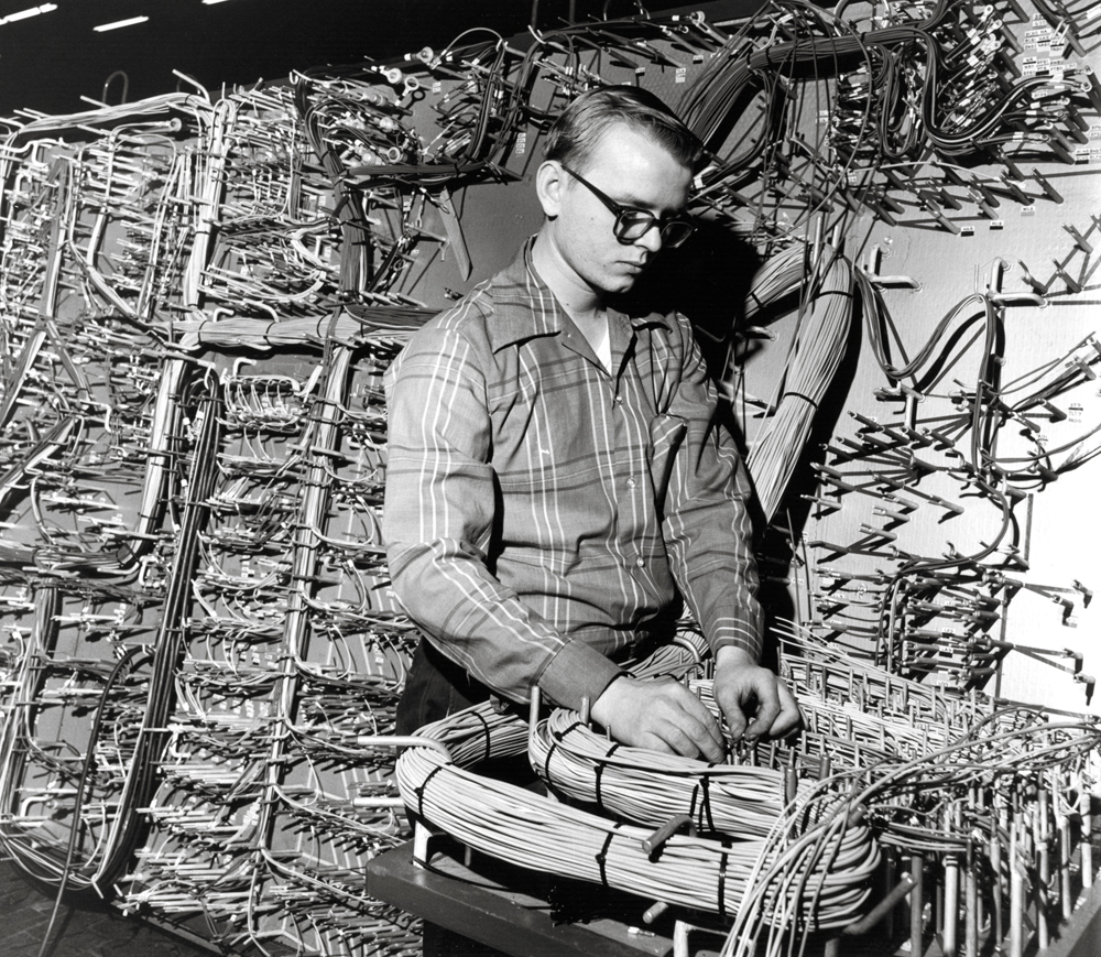
The problems of locomotive wiring with neoprene insulation were well known to maintenance workers and EMD by the 1960s. As a result, EMD engineers developed a new specification for insulating materials for both control wiring and power cables. At the time, the issue came to a head in the extreme heat and humidity of a Brazilian customer’s mining railroad.
The solution was a new insulating material. The product, from International Telephone and Telegraph Co., nearly matched the specifications EMD developed. Initially called ITT Surprenant Cable, this wire with superior insulating material came to be called Exane™ wiring. Irradiated with X-rays, the cable was used on transit cars, oil rigs, and in nuclear power plants. It performed well in temperatures from minus-67 degrees to 257 degrees Fahrenheit, while resisting the effects of oil, abrasion, impact, water, and flame. The downside of Exane™ is that for large conductors, the cable is stiff.
Exane™ wire, introduced in 1972, greatly extended locomotive life, earning it a place in the top eight. By the mid-1990s, some late-1960s GP38s had wiring with crumbling insulation — locomotive arterial heart disease. With no economical remedy, the solution was rewiring the entire locomotive. As a result, many locomotives were retired after 20-25 years, while thousands of Exane™-wired GP38-2s, GP40-2s, and SD40-2s remain in service today — some running more than 50 years.
No. 5: Wheel Creep
Low resistance between steel wheel and rail makes the railroad fuel efficient. What is good for railcars, however, creates locomotive problems, particularly in wet weather. Tractive effort — a locomotive’s pulling force — divided by the locomotive’s weight equals adhesion. Adhesion defines how well wheels grip the rail. Adhesion increases with tractive effort, but when adhesion is greater than the friction between rail and wheel, the wheel will slip. It doesn’t take much wheel slip for tractive effort to decrease. Steam locomotives had issues with wheel slip, as did the first diesel-electric locomotives, which depended upon the engineer to turn on the sanders and reduce power.
In the 1960s, EMD developed the Wheel Slip (WS) module and later the Instantaneous Detection and Correction (IDAC) module to automatically control wheel slip. This early system reduced power to the traction motors when wheel slip was detected. Even with these systems, the all-weather average dispatchable locomotive adhesion on units like the Dash 2s was just 18%.
Through years of testing, EMD engineers came to suspect limited, controlled wheel slip could be advantageous, particularly when compared with severing power to all motors. Adhesion is greatest when the wheels are slipping just a little, which is known as creep. EMD introduced this philosophy with its Super Series system on the GP40X and increased adhesion to 24%. The GP50s and SD50s used this technology. Enhancements were made to the wheel creep control systems until the SD70s produced 28% adhesion. Today, AC locomotives locomotive can achieve all-weather dispatchable adhesion of 33%. On good, dry rail, 44% adhesion is possible.
Controlled wheel creep systems work by monitoring traction-motor power demand, torque, the rotational speeds of one or more motors, and knowing the true ground speed. At first, motor speed was obtained by using axle alternators. Today, speed probes mounted on each traction motor are common. EMD determines true ground speed with a radar unit mounted behind the front pilot. Controlled wheel creep works with a closed feedback loop system. Utilizing the known traction-motor electrical torque and speed characteristics, the horsepower applied to the rail, wheel speed, and true ground speed, the control system will allow limited wheel creep to deliver more horsepower. Wheel creep is continually adjusted based on traction-motor torques, horsepower and rotational speeds. Once the full available horsepower is applied to the rail, wheel creep stops. Typically, wheel creep is utilized at low speeds, whereas full horsepower is applied at high speeds.
EMD patented this technology, but GE Transportation quickly developed a clever electrical engineering solution that accomplished the same results for its B36-7 and C36-7 units. Later, the benefits of wheel creep were reproduced by software in microprocessor control systems, first with DC and later with AC traction motors. AC traction provides superior wheel creep characteristics as the inverters can better control power to the motors. This is one of the factors contributing to the superior tractive effort of AC locomotives.
No. 6: Microprocessor Controls
By the 1980s, relay logic, often combined with solid state circuits, was rapidly being replaced across all industries by Programmable Logic Controllers (PLCs). Companies such as Allen Bradley, Fanuc, and General Electric were producing PLCs for process control. It was inevitable that PLCs would be used in diesel-electric control systems, first appearing aboard the six-axle GE C39-8 and EMD SD60.
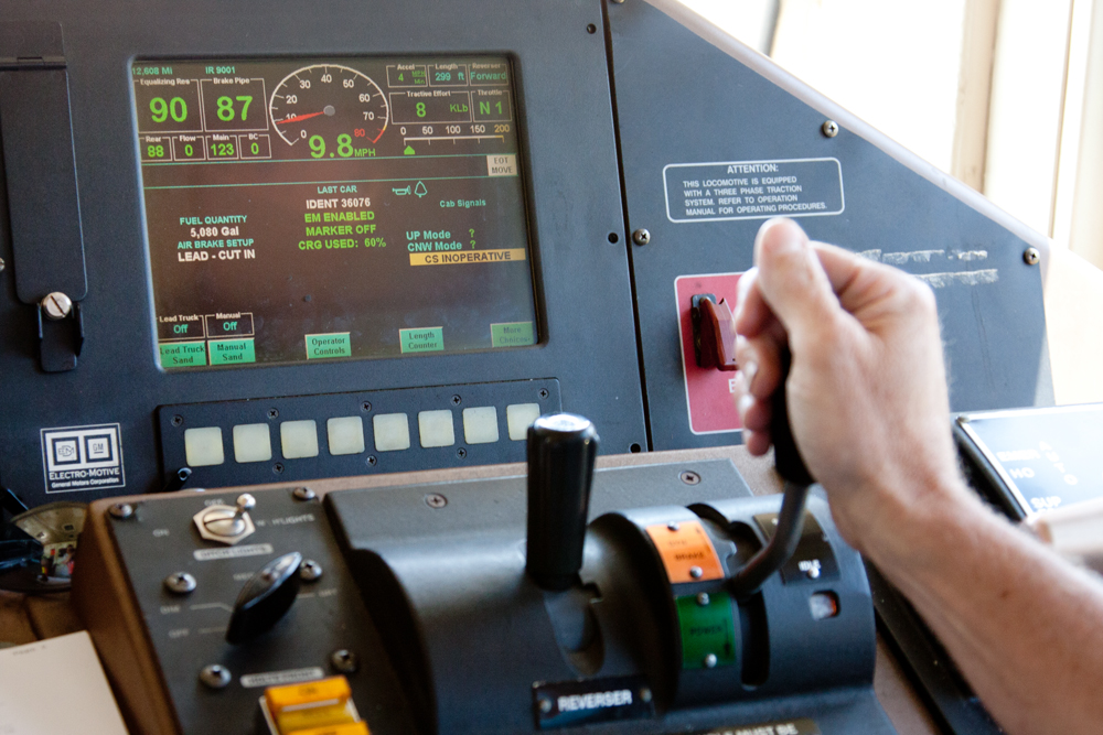
Just as in automobiles, microprocessor control changed locomotives into software-driven vehicles. Thanks to an array of sensors, locomotive functions from engine coolant temperature to fuel consumption are under programmable control. In fact, separate microprocessors have been introduced for subsystems such as diesel engine fuel injection and pneumatic brakes. Today, customized software is written for everything from emission control to helpful operator information. When locomotive modifications are necessary, rather than upgrade or replace physical components, most changes are made with new software releases.
No. 7: AC Traction Motors
When it comes to fixed-speed applications, AC motors have dominated for decades. Adapting AC motors to variable-speed applications, in lieu of DC motors, was a slow process. Variable-speed AC motors were adapted to manufacturing plants, rolling mills, conveyor belts, mining, and other applications. With the vigorous demands and complexity of motor controls, locomotives were one of the last applications to change to variable-speed AC.
AC motor design was not as much of a challenge as designing the motor control system. This was made possible when gate turn-off thyristor (GTO) technology was developed by GE. GTOs are high-powered semi-conductors that function as an inverter when controlled by a microprocessor, converting DC to AC current. Inverters, however, do not produce a true sinusoidal wave form. Rather, they generate pulse-width modulation that resembles a sinusoidal wave form. The combination of GTOs and microprocessors make variable-speed AC motors practical in robust, high-power applications.
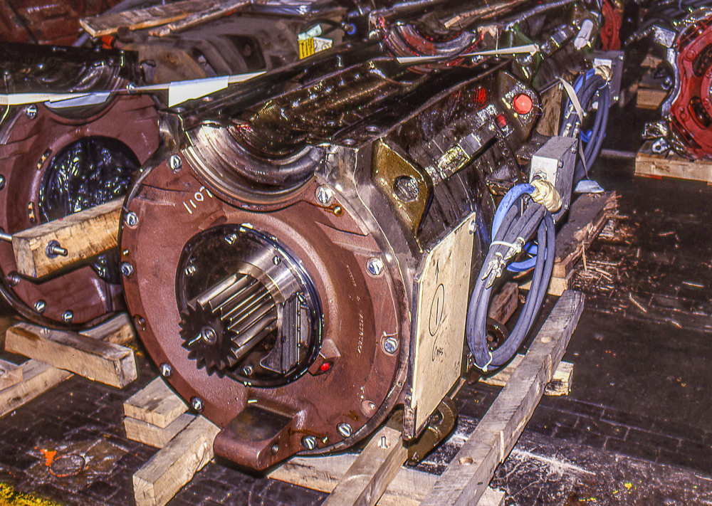
Eager to take the lead in AC propulsion, EMD partnered with Siemens for control systems and inverters. Siemens adapted an existing traction motor design to the North American market with one GTO inverter driving each three-axle truck. After a few SD60MAC proof-of-concept units, Electro Motive rolled out three AC models: the SD70MAC (4,000 hp); the limited-production SD80MAC (5,000 hp, 710 V-20 engine) and the less successful SD90MAC (intended for the 6,000-hp H engine; most received a 4,300-hp 710 engine). The new AC motors increased torque by a whopping 20% over DC predecessors, performed dramatically better at low speeds, and eliminated the “short time” motor ratings required to avoid overheating DC motors.
GE quickly replicated EMD’s initial success with AC traction, introducing its AC4400 (4,400 hp) locomotive. Despite BNSF’s huge order of the EMD SD70MAC for coal service, GE produced more AC units in the first generation of this locomotive type. An important difference between the SD70MAC and AC4400 was the use of GTO inverters. EMD used one inverter per truck to drive three traction motors. GE used one GTO inverter per traction motor. GE developed an extensive marketing campaign directed towards railroad management on the advantages of six inverters. This, combined with the higher horsepower and reliability of the AC4400 units, led to widespread acceptance. By 2017, Progress Rail was also using one inverter per traction motor — now called “single-axle” control.
No. 8: Distributed Power
The advantages of long, heavy trains have been known for decades. Longer trains require fewer crews and reduce fuel costs when heavy trains are closely matched to the tractive effort of the locomotives. Today, all Class I railroads are running more distributed-power trains.
Distributed Power™, as we know it, began on the Southern Railway during the innovative time of President D.W. Brosnan [see “When little trains made big trains,” February 2023]. As diesel-electric locomotives became more powerful, Brosnan espoused the vision of a “1,000-axle train,” utilizing remote-control, mid-train locomotives to make 250-car trains possible. To achieve this, he tasked the electrical engineers of his Signals and Communications department to design a system mimicking the actions of an engineer on the lead locomotive.
Combining germanium (a shiny gray semimetal) logic transistors with Westinghouse Air Brake’s electrically controlled spool valves, the communication engineers used radio (VHF initially, later UHF) to remotely control the mid-train locomotives. Southern Railway supplied drawings and specifications to North Electric Co. of Galion, Ohio, which produced the RCE (Radio Controlled Equipment) or RCS (Radio Control System). Southern began testing the system in the early 1960s. The first production systems were introduced in 1965. (North Electric was purchased by Radiation Inc. of Melbourne, Fla., in 1963.) The hardware was large and clumsy by today’s standards. Southern opted to place the radios, circuit boards, and air brake equipment for remote units in ballasted, M.U.-equipped boxcars. The perceived advantage was the ability to use any locomotives in the remote consist. Dedicated control locomotives at the front of the train had hardware placed on the control stand and in Southern’s characteristic high short hood.
In addition to crew and fuel savings, distributed power offers other advantages:
- Reduced in-train forces make longer trains less susceptible to coupler and draft gear failure leading to break-in-two events.
- Reduced in-train forces help track structure by lowering lateral forces between the wheels and rail in curves.
- Faster, more uniform application and release of train brakes, as remote units immediately respond to the automatic brake valve.
- Compared to trains of the same length and tonnage, distributed power trains move across the railroad faster and may require less power.
- Reduction in string-line derailments where lightly loaded or empty cars on the head end are pulled off the rail in curves.
In retirement, D.W. Brosnan, who was heralded for his many productivity accomplishments, promoted using RCE trains. Santa Fe, Canadian National, Canadian Pacific, and the Quebec, North Shore & Labrador railroads all embraced DPU technology. By the 1970s, independent control of remote locomotives was possible and Southern Railway began experimenting with multiple remote consists. After Harris Corp. acquired Radiation, Inc. in 1967, Locotrol™ II was introduced, with smaller hardware installed in the locomotive cab and short hood. Locotrol™ III followed and was compatible with Wabtec’s EPIC and New York Air Brake’s CCB electronic brake systems. With the introduction of Distributed Power™, GE heralded a technology that could handle multiple remote consists, a feature increasingly used today.
While locomotives are assembled on virtually every continent, North American designs have been the preferred heavy-haul motive power. Not only have American locomotives set the standard for rugged, dependable, pulling power, but they have paved the way for new technology. As a result, locomotives from EMD, now Progress Rail, and GE Transportation, now Wabtec, continue to offer unrivaled value for their owners as far away as Africa, Australia, India, and numerous other Asian countries.


Little known Fact: Back in the 1970’s, EMD was trying to sell Southern Railway ASEA electric locomotives for a proposed electrification of the CNO&TP route. They touted the improved adhesion that could be obtained with thyristor chopper control circuts to control wheel creep. Mr. Neil Coggins of Southern said “well, if you can control wheel creep on an electirc locomotive, you should be able to do it on a diesel locomotive, because it’s just a difference of where the electricity comes from”. EMD begrudgingly agreed and that became the birth of what was called “super-series” wheel slip control. It cost EMD loco sales since two super-series locos could replace three IDAC locos in certain situations. First came the GP40X, which I was involved in testing, and that morphed into the GP50 and SD60 locos. I will never forget How the train crew was laughing when we told them that these four GP40X locos would do the same work as four SD40-2 locos on our AWW unit coal train. When we proceeded to pull the ruling grade 2 MPH faster than the six axles, the laughter turned to smiles. Quite a breakthrough!
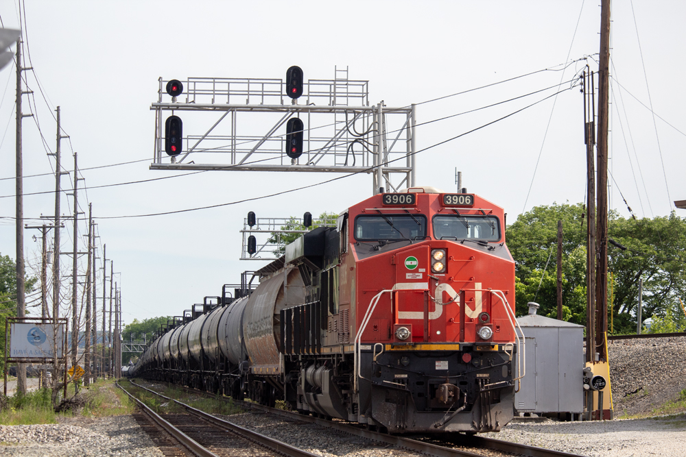
A somewhat slanted perspective, implying EMD was the primary innovator in more than its share. Mr.Christensen has already pointed out that ALCo produced the first AC-DC transmission in a diesel electric locomotive, presumably with the help of GE. Canadian National did a lot of its own development on wheel slip control to improve performance of their EMD fleet. Yet on the other hand, CN was a latecomer to the party when it came to remote control, and also chose to remain with DC traction motors instead of paying the premium for AC motors. (They have now, belatedly, embraced both.)
With respect to dynamic braking: The regenerative braking feature on the Milwaukee’s circa 1916 electrification turned out to be far more valuable in improving train handling than the savings in electric energy. So I would expect that the impetus for developing dynamic braking for diesel electric locomotives was largely based on experience with regenerative braking in electric locomotives.
ALCo pioneered and produced the first AC-DC transmission in a diesel-electric locomotive; their C-630 was purchased by the ACL railroad .