


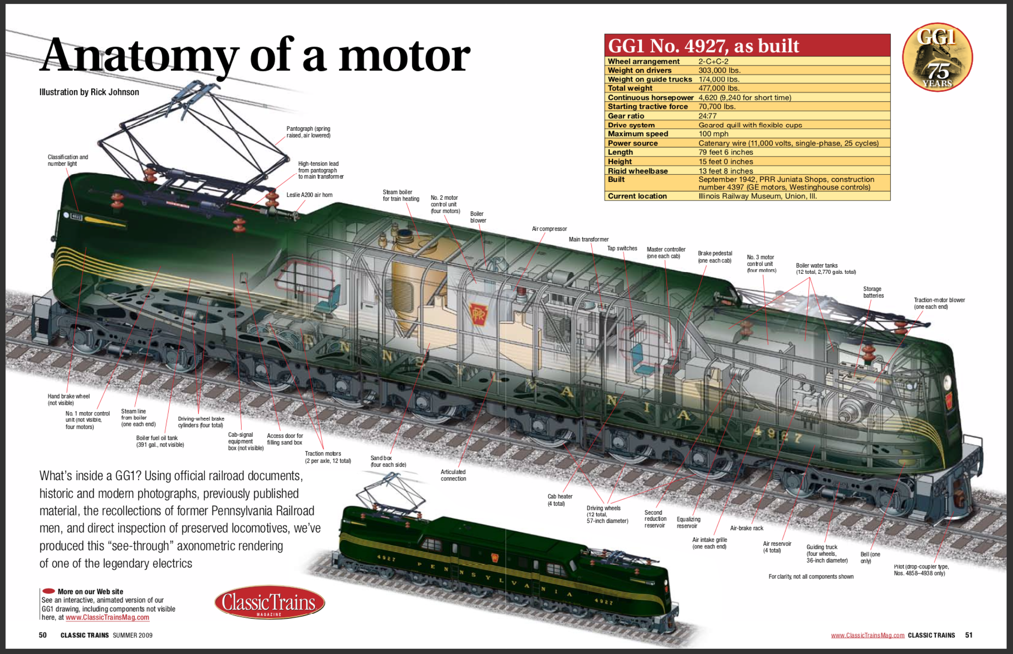
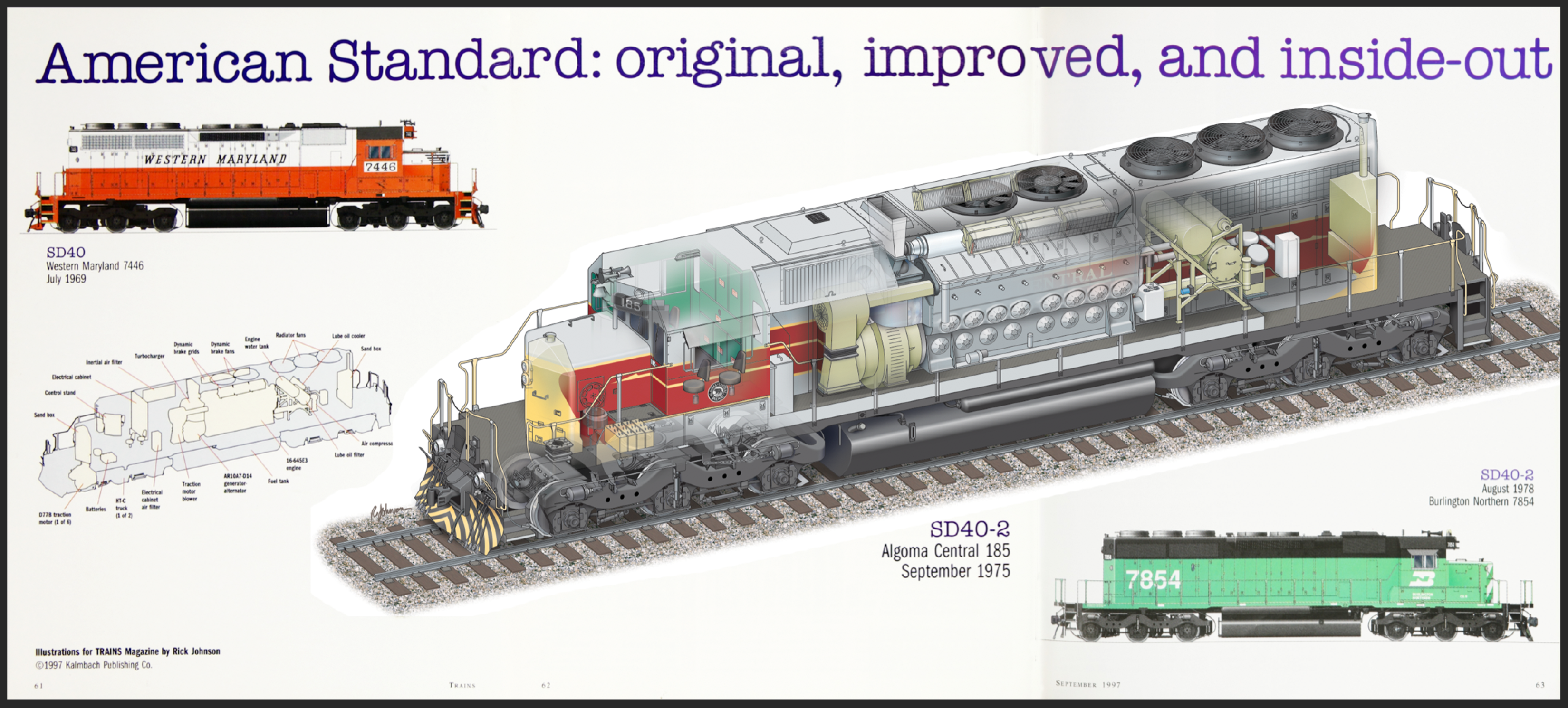
Those words from a retired Kalmbach Media vice president sent a bit of a shiver down my spine as well as sparked a challenge I found irresistible. I’d love to do it, but it’s substantially more complex than either the SD40-2 I drew for the September 1997 issue of Trains or the GG1 cutaway I drew for the Summer 2009 issue of Classic Trains.
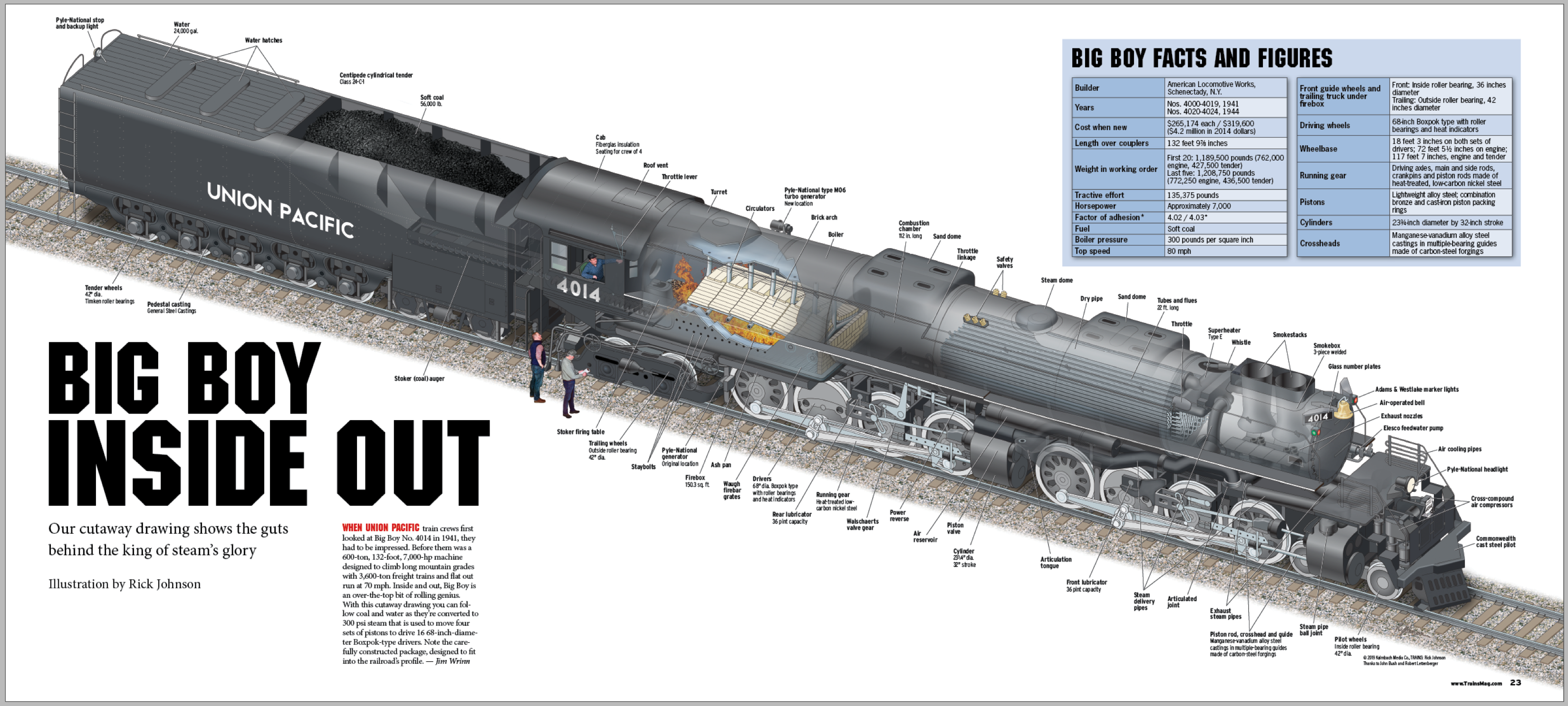
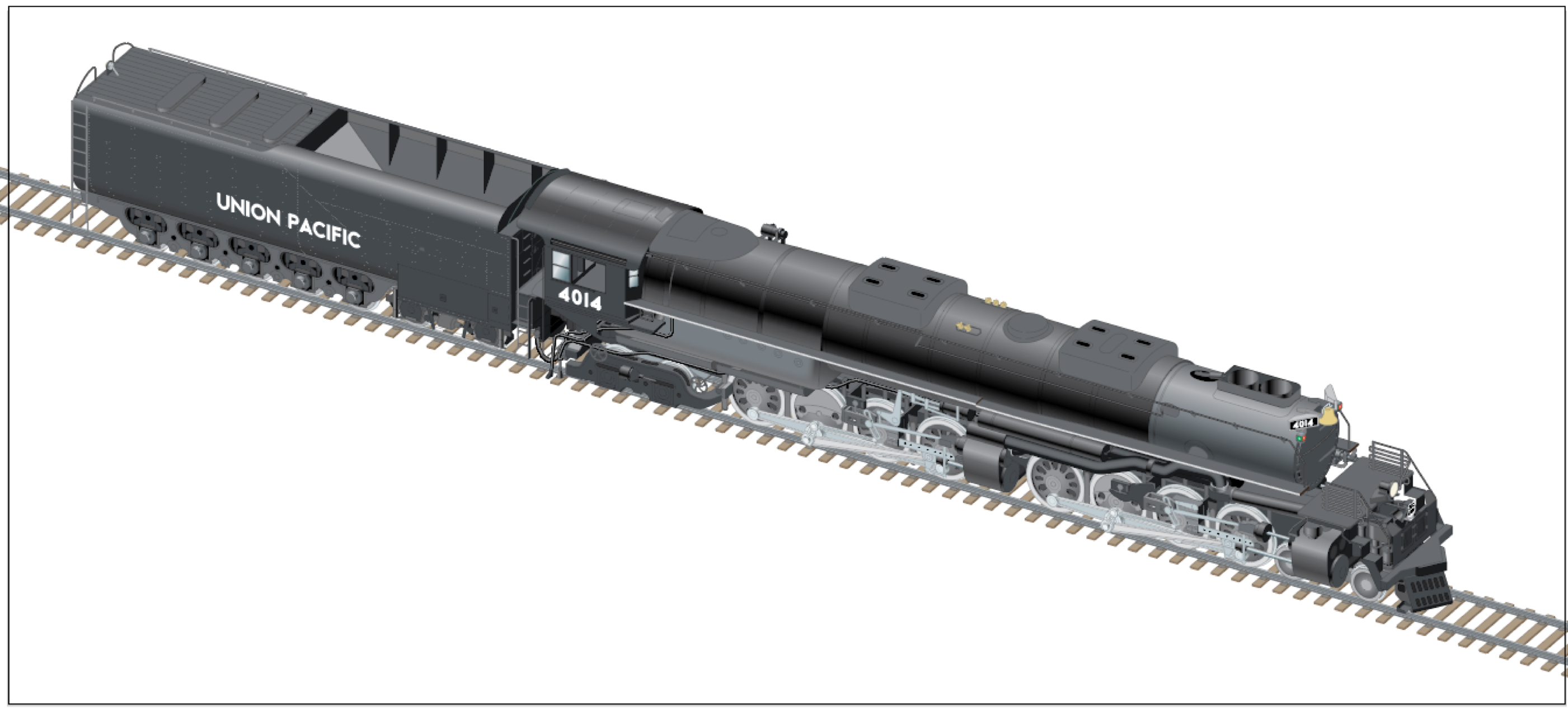
But, we knew Big Boy 4-8-8-4 No. 4014 was on the Road to Restoration, and surely needed a worthy drawing for our coverage.
Here’s how I went about drawing a version of the famous locomotive, digitally.
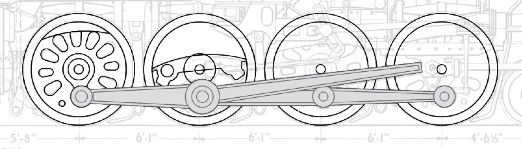
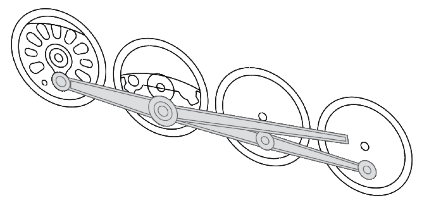
The steam locomotive posed more of a challenge, though, in that its components couldn’t be “snapped” to a floor plan or built up like blocks. The spatial relationships of the pieces had to be correct, but positioning them wouldn’t be nearly as straightforward. In addition, there is simply a lot more parts to show in a steam locomotive.
Gulp.
Any steam locomotive would be a tall order, but the Big Boy is about as intense as a steam locomotive can get. And once the project gets started, there’s really no opting out.
The project began in August 2018, to be done in an on-and-off fashion between work on issues of Trains, Model Railroader, and other Kalmbach publications. The primary references for my drawing were a scanned image of an actual blueprint of the Big Boy as well as a drawing by E.W. Bearman in Kalmbach Books’ Steam Locomotives Cyclopedia — Volume I compiled by Linn Westcott. Kalmbach’s David P. Morgan Library had a good variety of photos of Big Boys, as well as William W. Kratville’s 1972 book “Big Boy” which contained a lot of photos of the locomotives under construction.
A 1941 Locomotive Cyclopedia provided details on components such as superheaters and stokers. With some oversight by John Bush and Robert Lettenberger, I was in a good position to draw the Big Boy.
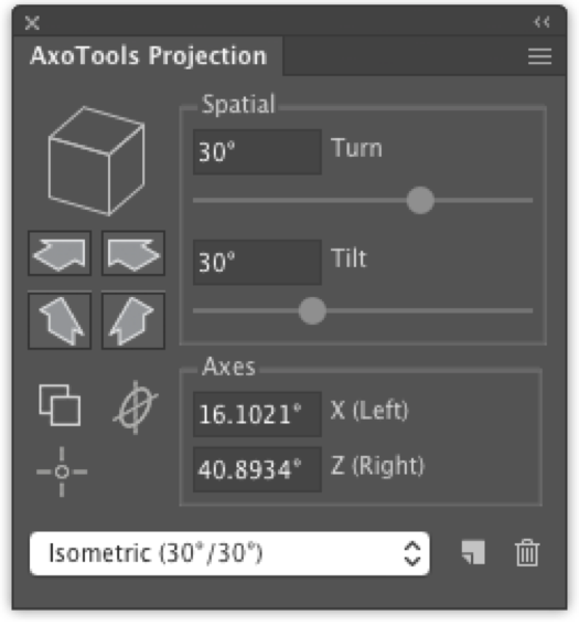
Using the CADtools plugin from Hot Door Software, I sized the scanned images to my drawing scale of 3/16-inch equals 1 foot and began tracing. CADtools can project flat art to axonometric planes, but the challenge with this drawing was in correctly positioning the pieces. I’ve also been writing plugins for Adobe Illustrator since Adobe first added support for that in 1993, and one of my recent projects was a specialized tool for projecting flat orthographic art into its correct position in a 3D axonometric view by first marking corresponding points in the top, front, and side views.
Sometimes the drawings showed “almost” enough detail for some areas and other plans were down to the fastener level. It was like working with computer technical support, where the information given was very accurate, but not very helpful.
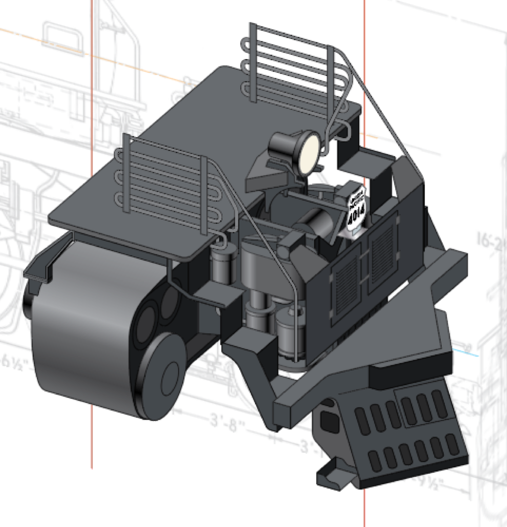
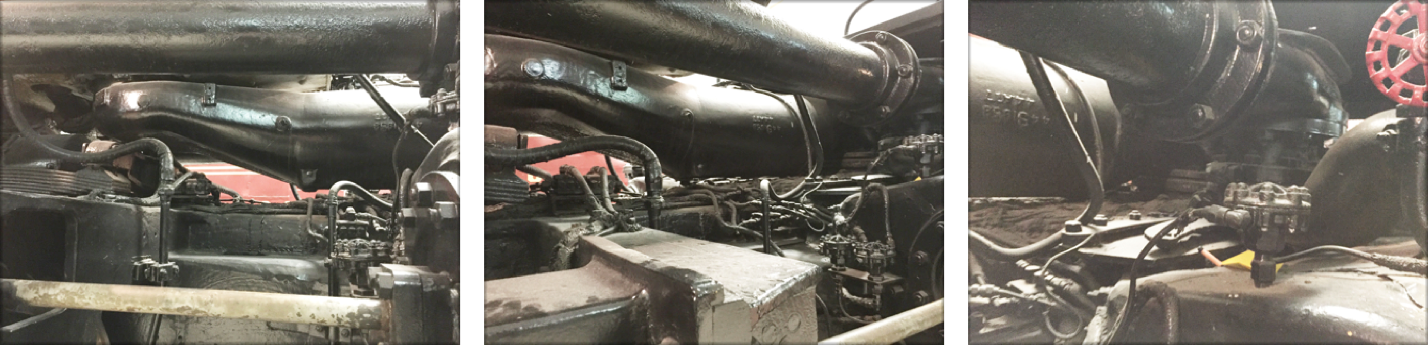
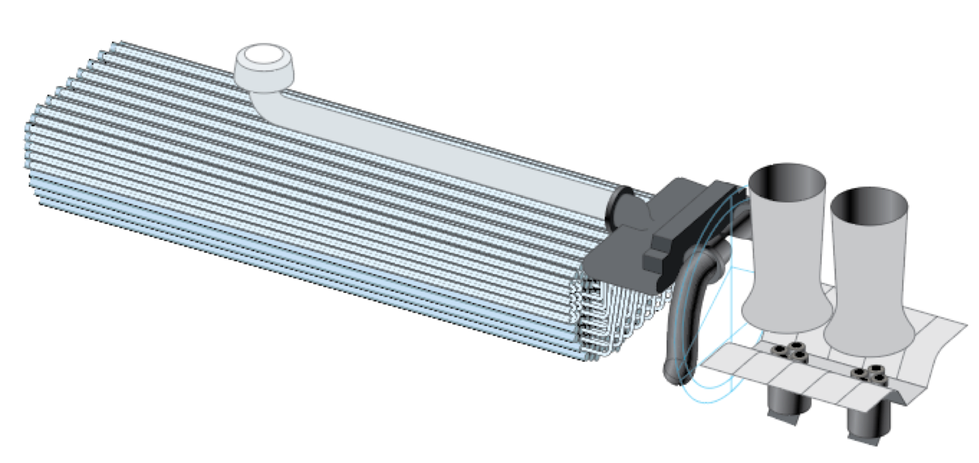
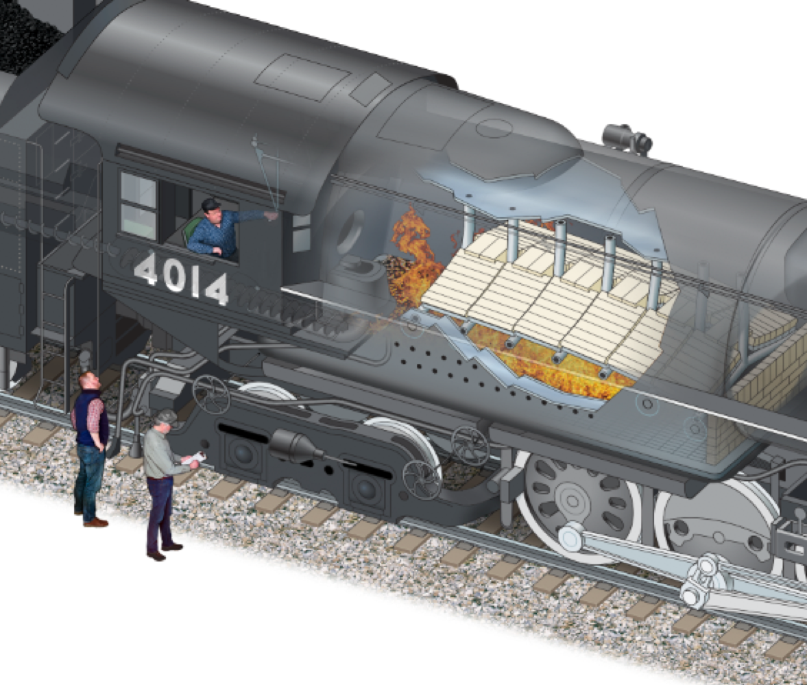
Fortunately, Kalmbach is located a couple of hours away from Green Bay, Wis., so I took a trip to the National Railroad Museum. There I could take notes and reference photos of the Union Pacific 4-8-8-4 No. 4017 on display there, which was incredibly helpful. For example, the organic shape of the single center front exhaust pipe was one of the day’s best takeaways, along with the swiveling fitting at the front cylinder.
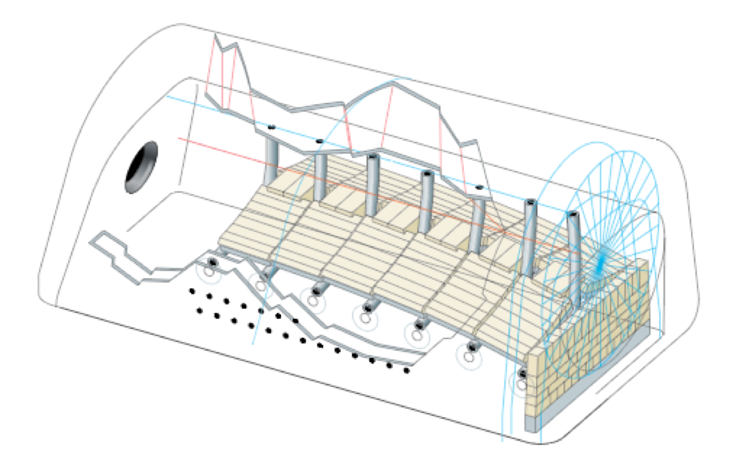
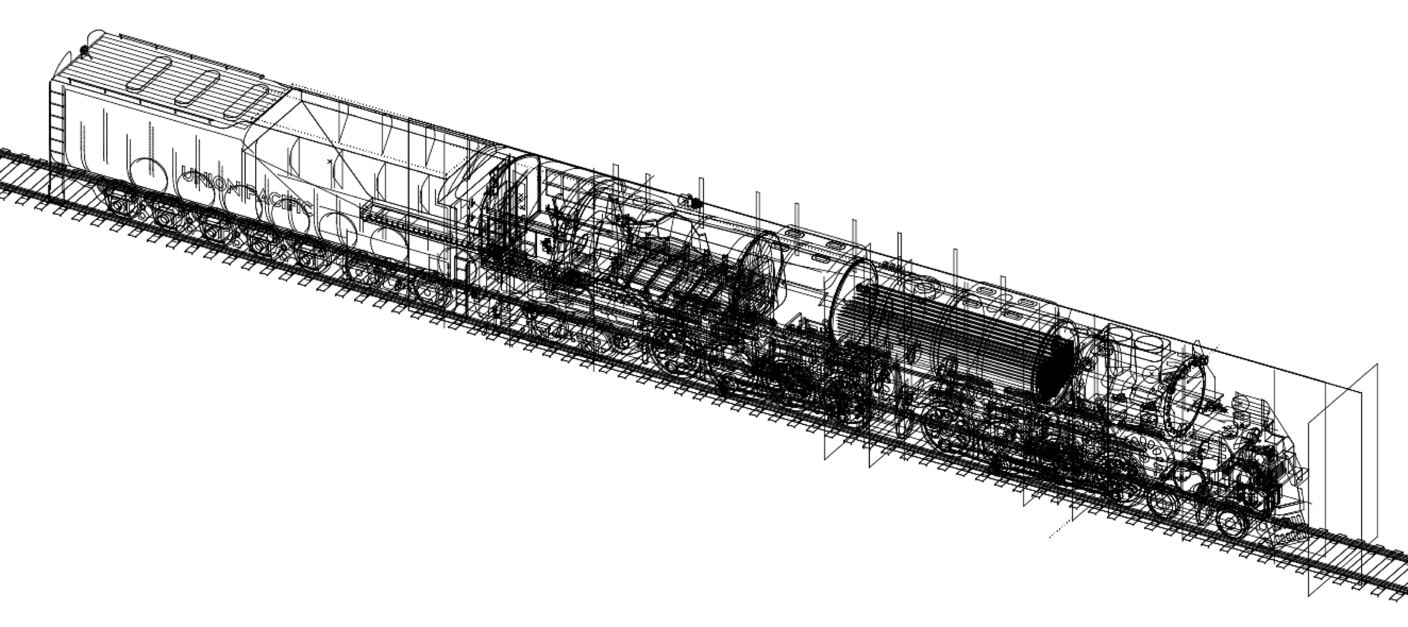
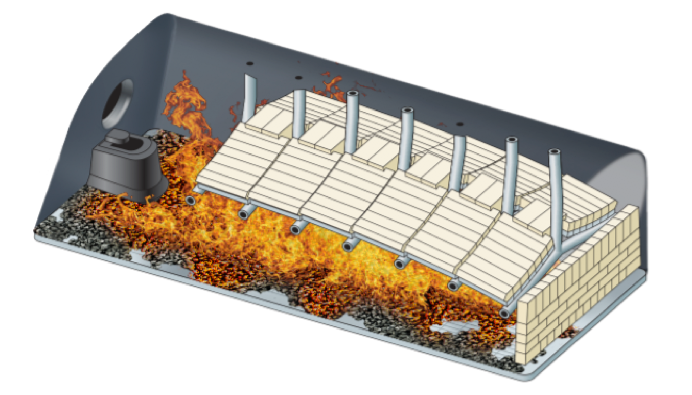
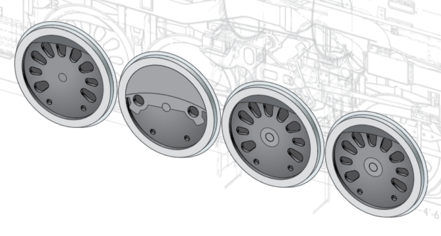
This view of the firebox interior with painted coal and fire is a combination of 16 layers, although the final view includes more intermediate layers and vignetting with layer masks. The final Photoshop file contains well over 100 layers.
The ballast and shadows under the locomotive are placed on lower layers below the rails. In any illustration like this, there are always areas where one has to make a compromise between what to show and what not to so that the reader gets as much useful information as possible, and in a way that everything one sees makes sense.
The front platform is translucent to show how the front pipe is jointed in three places to allow the front to swing side to side, and how the single exhaust pipe runs back from the center of the front cylinder casting while the rear exhaust pipes join in a tee. At the left of this image is the phantomed tongue of the front frame section, which was added to show the point where the locomotive is articulated.

That is great work Rick, I am based in the UK and would like to get a scaled collection of drawings for the UP BB so I can build in 7.25″ gauge for the UK track. Where can I source these drawings?
That was an amazing work of CAD skills! I am based in the UK and would like to make a live steam version of the UP Big Boy. Do you supply build drawings or some scaled files? I cannot see any source of these drawings? Can you suggest a source?
that is awesome, Rick, and thanks for telling us how it was done. I have the mag and looking at picture as I was reading how you made it happen. I think my friends and I met you in June 2018 when Cate and Brian showed us around Trains office. I remember your name and I think you do a lot of the map illustrations too. My friends Lee and Susan were with me. We all met Cate thru Facebook and were able to meet up for lunch when we passed thru Milwaukee on way to the Dells for train trips. We did get to Ogden to see #4014 and also West Chicago and I met up with Susan in Kansas City a few weeks ago. Fantastic.
Thank you and TRAINS for sharing this invaluable rendering!
As someone who long ago taught drafting in the T-square/triangle era (before getting more money and a better pension on the railroad), CAD drawing is pretty amazing. For engine restorers, recreating long-missing boiler jackets is an excellent use of the process, well worth an article in Trains magazine.
Rick, thank you for sharing the process behind a beautiful and technically impressive illustration. You’ve inspired at least one greenhorn illustrator — especially with the 2D-to-3D projection plugin!
Rick, Wow, thank you, another masterfully finished drawing. I’ve been enjoying your drawings for decades now, for many magazines, etc. I love the way you told this story of your drawing break-down. Kudos to Trains and Kalmbach for getting you to do this one as well.
Michael, the Photoshop file is about 185 MB.
All I can say is WOW, what artistic skills and computer talent! I’m envious, jealous, and awe-struck. I had to read it twice even to begin to understand how you did this. Kudos!
Well Done!
Thanks for the comments! I’ll check the file size when I get back to the office on Monday — great question. The image is about 12 x 24 inches at 300 dpi, and about 120 layers.
The water pipes are on the far side of the locomotive, running all the way to the front of the boiler. I agree, that would have been nice to add. The only elevation drawings I had were from the engineer’s side, which influenced the decision to draw it from this angle.
What was the size of the final file?
It doesn’t show how water is delivered to the boiler.
Well done. Thanks for the information. From now on any drawing will be a piece of cake. The Big Boy drawing presents a real challenge and it looks great.
Would be better in the magazine than in Newswire .
Very impressive and very nice; Well Done Rick Johnson.