


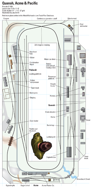
The Quanah, Acme & Pacific: Four oNeTRAK modules plus more
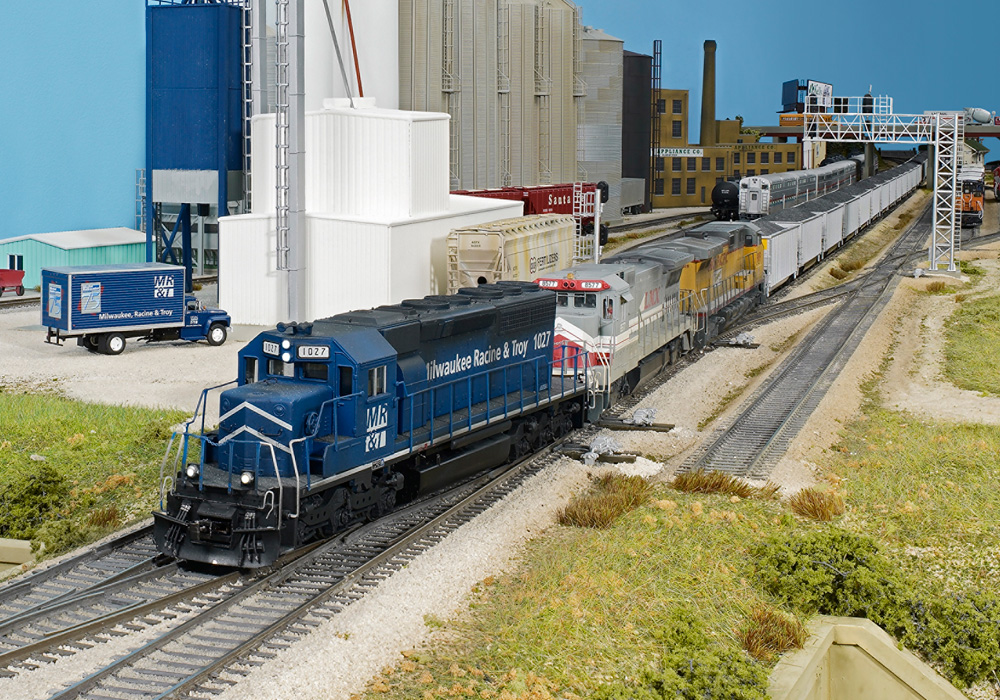
I’ll admit it, I have a thing for steam-powered short lines. Let others run their Empire Builders and Challengers and Super Chiefs; I’d rather be behind the throttle of a Consolidation pulling an eight-car peddler. Those name trains may have the glamor, but I prefer to model the days when every road with “Pacific” in its name could dream of someday reaching that goal.
One such little railroad with big dreams was the Acme, Red River & Northern, founded in 1903 to serve a pair of gypsum plaster plants in Acme, Texas. The other end of the railroad was a wye connection with the Fort Worth & Denver at Quanah, six miles east of Acme. To convince Texas authorities to grant it common-carrier status, the road changed its name to Quanah, Acme & Pacific and drew up plans to build westward, with the eventual goal of the Rio Grande River at El Paso, Texas.
Though it never got that far, the Quanah’s potential to open up the largely unserved Texas panhandle drew the attention of the St. Louis-San Francisco, which bought the short line in 1911. This track plan is set in early 1929, after the Quanah finally reached a junction with the Atchison, Topeka & Santa Fe in Floydada, Texas. This added bridge traffic to the Quanah’s mix of short local freights and mail-express trains. After reaching Floydada, the line also added its own prestige streamlined train, The Plainsman, to supplement its mixed-train and motor-car passenger service.
I had two goals for this track plan. The first was to represent two important towns on the route as oNeTRAK modules, a format well suited for a single-track, flatland road like the Quanah. My second goal was to devise a home layout into which these modules could be plugged, providing additional industries, a continuous run loop, and sufficient hidden staging to model the Frisco-to-Santa Fe bridge traffic in a convincing manner.
Each side of the donut-shaped track plan includes two four-foot-long oNeTRAK modules, though each set
is intended to always be operated together, separating only for transport.
Since it’s not easy to find prototype track diagrams for the Quanah, this layout is more freelanced than prototypical. I did get some ideas from Google Maps, though. The stations shown here, as well as the Paducah freight ramp and the industry there that I labeled as a cotton compressor, are still visible in Street View.
The plaster plant at Acme, the largest industry on the layout, includes basic support structures for a dedicated switcher, though they could be replaced with more car storage tracks. In addition to this factory, Quanah and Paducah have a mix of the industries that provided the region’s lifeblood, including cotton, cattle, and wheat.
A typical operating session could start with bringing a Frisco train in from staging and breaking it down into cars intended for Quanah, those slated for industries down the line, and bridge traffic for Floydada. The daily local could then set off for Acme and Paducah, while the Quanah operator delivers local cars. If a third operator is available, he could complicate things by running a motor-car passenger local or The Plainsman.
After switching Acme and Paducah, the local would head into staging. Another train, hauling cars from the Santa Fe, could then head back up the line toward Quanah. – Steven Otte
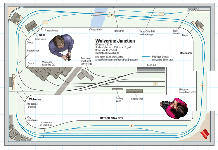
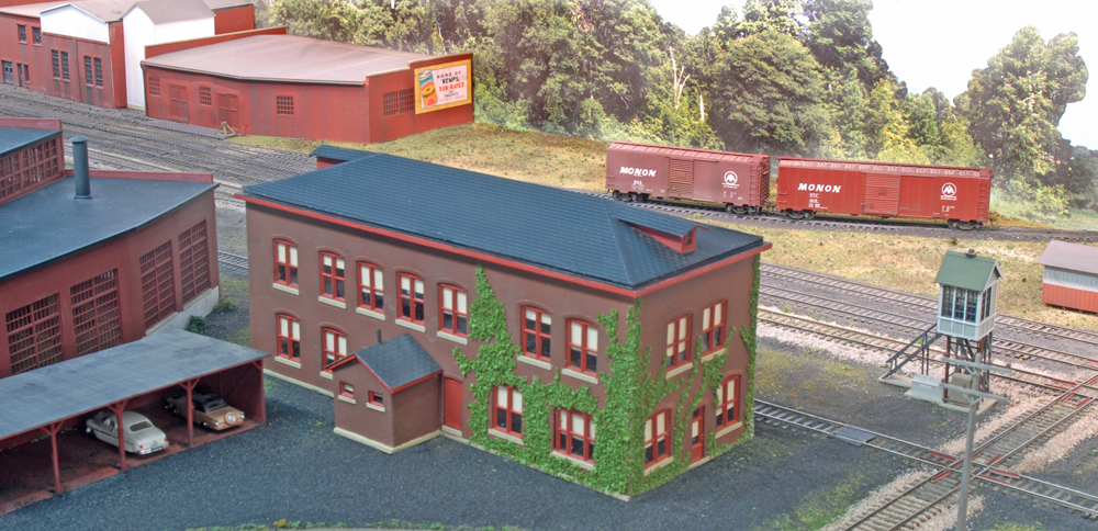
Wolverine Junction: An HO scale walk-in layout with a branch line
As I started designing this around-the-walls track plan, my eyes kept returning to a Bachmann HO scale General Electric 45-tonner on my shelf. I like rural branch lines, especially those on the New York Central System in the transition era. However, I’m also a fan of shelf switching layouts and diminutive industrial diesels.
This freelanced track plan combines the best of both. The around-the-walls section is inspired by the Michigan Central RR’s Bay City Branch. The Bay City yard serves as visible staging for trains running in both directions. The freelanced Wolverine Short Line that interchanges with the MCRR adds extra operating fun.
Because much of the plan is on a narrow shelf, many of the structures would need to be flats or low-relief models, or structures that extend into the aisle. For example, I would model Yates Cider Mill with a prototype photo attached to the backdrop.
For the most part, train length on the Bay City Branch is limited to one locomotive, six to eight 40-foot freight cars, and a caboose. For motive power, I’d suggest an Electro-Motive Division GP7 or F unit.
Passenger operations wouldn’t take up too much space along the Bay City Branch. In the mid-1950s, the MCRR used a Budd Rail Diesel Car (RDC) to handle passenger chores on this line.
A small switcher, such as that GE 45-tonner, would work the Wolverine Short Line’s yard, interchange, and industries. A speed limit of 20 scale mph would extend the length of the run. The WSL might also have trackage rights to one of the towns along the Bay City Branch.
Industries, scenery, and equipment could be modified to make Wolverine Junction represent a different era and locale. The plan could also be adapted to N scale for longer trains, bigger industries, and a longer main line run. – Dana Kawala
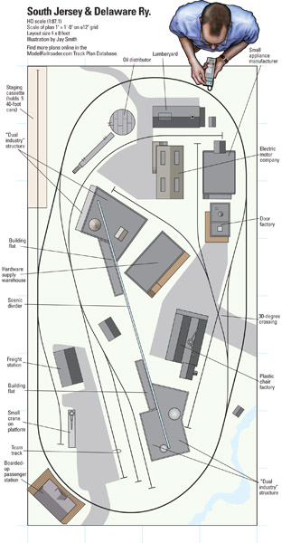
The South Jersey & Delaware: A double-sided 4 x 8 in HO scale
The South Jersey & Delaware Ry. is a 4 x 8 layout based on an HO scale track plan drawn by Don Mitchell and published in the December 1978 issue of Model Railroader. Don’s original Oakville Central plan used 15″ radius curves to fit the HO scale layout in a space about 3 x 6 feet. This plan enlarges the layout to 4 x 8 feet to use 18″ radius curves and fiddle cassettes that allow staged trains to be quickly swapped onto the layout.
The plan can be built with HO sectional track, although fitter pieces will be needed to align the 30-degree track diamond on the right side of the layout and three of the turnouts along the left side. The layout has no grades.
As Don noted in his story, the focus of this plan is switching small industries, but a continuous loop is included “for those times when just plain running trains is the order of the day.”
This plan is set in the mid-Atlantic area in the late 1970s. That era wasn’t a high point for American railroads, but it was an interesting time for rolling stock and locomotives. The end of the Penn Central in 1976 and Conrail’s rise from its ashes created a colorful mix of Eastern rolling stock that would be appropriate for this layout. Only one or two diesels would be needed.
The industries on the layout are all rail-served. I added a 24″ tall central scenic divider to Don’s original plan to keep an operator from seeing both sides of the layout at once. To disguise the edges of the divider, structures wrap around each end. By applying two sets of signs, separate loading docks, and different colors of paint to structure walls, each can model two different industries. – Neil Besougloff
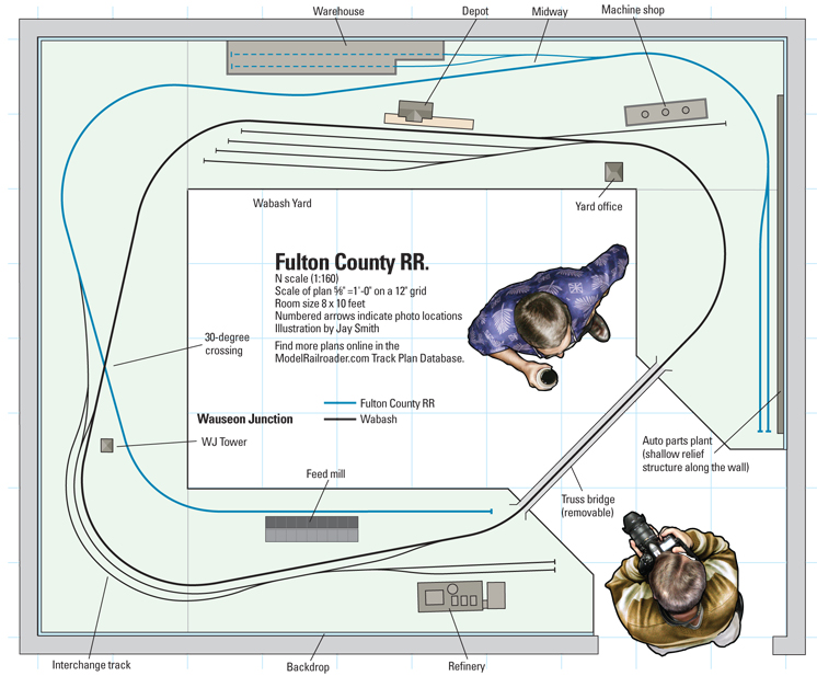
The Fulton County RR: A short line with a Wabash interchange
This freelanced track plan offers a mainline loop for continuous running and a point-to-point terminal railroad with industrial switching. It’s designed to fit into a spare bedroom, with wide curves and no. 6 turnouts to make switching more reliable and accommodate hi-cube auto parts cars.
The layout’s activity is centered around moving traffic between the Wabash Yard and the interchange at Wauseon Junction. From there, the Fulton County RR’s single road switcher transfers cars to the warehouse at Midway or the Ford auto parts plant at the end of the line.
The mainline loop allows a Wabash road train to build up as much mileage as desired on its way to the Wauseon Junction interchange. A switcher can work the yard at the same time. After switching the refinery and delivering the interchange cars to the FCRR, the Wabash can return to its yard.
The FCRR engine then takes its inbound cars over to Midway Siding, where they’re sorted and lined up in proper door order for delivery to the customers’ plants (kitbashed shallow relief structures along the walls).
Though the railroad has only a few online industries, N scale allows them to be big enough to convincingly require rail service. Even so, the area surrounding Wauseon Junction has plenty of room for open terrain, making the mainline run feel longer. If more switching opportunities are desired, there’s enough room along both lines to add team tracks, passing sidings, or other industries.
The benchwork is designed to be built in sections. This makes it easy to construct the parts elsewhere and bring them in for installation, keeping sawdust and noise down. It also eases disassembly in case the layout must be moved in the future. – Jim Hediger

PDF links DO NOT work