


When I began exploring the ins and outs of railroad operations as a teenager, a lingering question piqued my curiosity: Why do multiple diesel locomotives run together in the same or different directions? The answer is quite simple once you understand how the operating practice works.
Most North American locomotives today are diesel-electric, meaning that they’re essentially electric vehicles with onboard power generators fueled by diesel. Simply put, the diesel engine powers the generator, which in turn powers an electric motor on each axle.
A group of modern locomotives work together using a set of electrical cables and pneumatic hoses located on each end plate of a locomotive that ensure synchronization between all engines in the consist. Known as Multiple-Unit control (MU), this technology was created by Frank J. Sprague in 1896, specifically for the elevated railways of Chicago. It soon became the norm on electric rapid transit systems worldwide, as cars could be coupled together from either end while eliminating the need to turn them at destination points.
The concept was adopted over time by diesel-electric locomotive builders beginning in the 1930s. This allowed builders to meet the horsepower demand for heavy freight trains since the new form of motive power was nowhere near as powerful as its steam predecessor. Yet the advantages to the multiple-unit technology in diesels outweighed this drawback. Most early road consists were MU-ed together by the builders in a semi-permanent fashion, with solid drawbars between each locomotive. These consists were used to mimic the total horsepower output of the steam locomotives they were intended to replace, but many railroads quickly saw the advantage of having couplers on each locomotive and the ability to build consists of different sizes that matched the tonnage for each train they operated. They would come to either order power with couplers from the factory, or remove the drawbars between locomotives in-house on consists already on the property.
The common 27-pin MU cable used on all locomotives today was first introduced by EMD in the 1940s, but 12-, 16-, 17-, and 21-pin cables were used on older models and builders. It wasn’t until the Association of American Railroads issued its first standard in 1969 regarding the MU cable that the electrical connection became more unified. The standard spelled out what each receptacle point on the 27-pin cable would be used for, with many assigned as ‘spare’ to allow additional options be carried between locomotives by different railroads if desired.
How does each engine in a multiple-unit consist know which way to go when moving? Pin eight and nine in the 27-pin MU receptacle located on each end of the locomotive is reversed, so each locomotive knows which way the adjacent locomotive is facing after the cable is plugged in, allowing it to operate in the correct direction when commands are sent from the lead locomotive.
Pneumatically, the modern locomotive setup has three MU hoses on either side of the coupler. Each group of three is a duplicate of the other. While a minimum of three hoses have to be coupled to MU locomotives together, any combination of 3 to 6 hoses can be coupled up during MU operation. The inside pair of hoses closest to the coupler are the main reservoir hoses which connect the main air reservoirs of each locomotive. The middle two are actuating hoses, used to bail off the locomotive brakes following an application of the train brakes via the automatic brake handle. The outside pair are the application/release hoses for the independent brake on the locomotives.
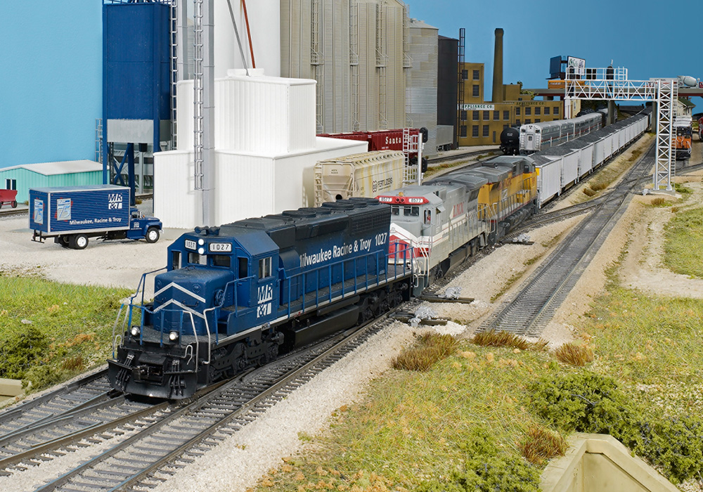
Diesels could also operate “back-to-back” with a cab facing in each direction. With an equipped cab unit (or A unit) on each end, yard or shop crews didn’t need to turn the locomotives, saving the railroad time and money. Today, motive power planners or diesel shop personnel on Class I railroads typically follow guidelines for each train on the system when assigning power. If a train is departing a large terminal and will terminate at another large terminal, the direction of trailing locomotives would not matter since the consist would typically be sent to the diesel shop and most likely changed to match the needs of its next assignment. But if a train departs a terminal and its destination is a location that has no way to turn the consist, it will be dispatched with an outward-facing locomotive on each end.
You won’t often see modern diesels running “backward” in the lead position on a mainline freight train today, mainly due to the requirement of working ditch lights on trains operating above 20 mph over public crossings. To save money, most road locomotives aren’t equipped with ditch lights on both ends. Older locomotives equipped with desktop control stands or standard control stands designed for the engineer to face one way make for an extremely difficult trip for the engineer if leading a train and the locomotive is facing the wrong way.
Learn more about how to create a multiple-unit consist using Digitrax.
Updated from its original version first published on April 5, 2023, by Trains.com staff and contributors: Lucas Iverson, Chris Guss, and Scott Hartley.


Steam locimotives have directional suspensions. The lead trucks have different suspensions from the trailing trucks and they can not run backwards as fast as forward. The Reading T-1’s you show above had a speed limit of 65 forward and 35 backward in R.Co. days. Naturally on Iron Horse Rambles on the New York Branch I clocked them at track speed of 75. There were always plenty of officials around and often a shop guy was on the engine so I guess the overspeed was allowed.
Seaboard Air Line (now part of CSX) probably started the idea of running the engines “elephant style.” In 1940 they split their Florida trains into East Coast and West Coast at Wildwood FL. The road power made the cuts. With MU diesels, they wanted to split the power there as well but the 60 degree nose slope of an EMD E3 prevented nose-to-nose coupling. EMD produced the E4 which had nose MU and couplers that extended far enough to allow nose-to rear coupling. This way the power consist could be split with all the cabs pointed in the right direction.