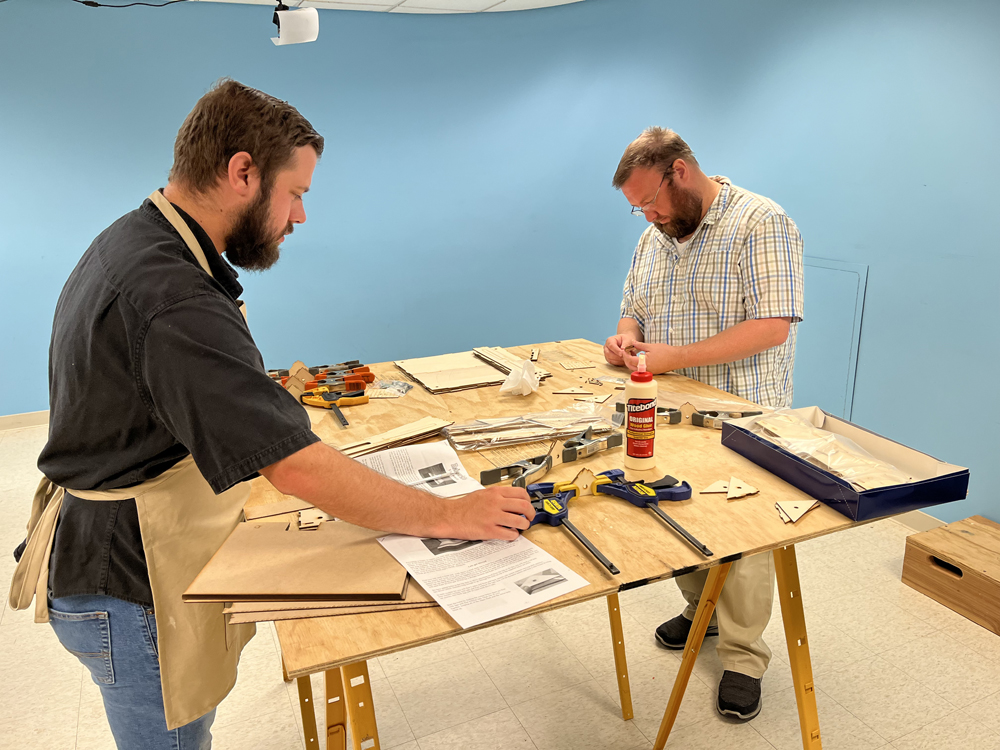
Modelers David Popp, Brian Schmidt, and Bryson Sleppy continue their series of projects to build a modular T-Trak N scale layout. T-Trak is a modular N scale railroading system that uses foot-wide boxes that can be plugged together to build tabletop layouts. In this second installment, the team demonstrates how to build RS Laser Kit module kits made from laser-cut micro plywood panels.
Bryson: David started this project for his new N scale book by purchasing a corner, two straights, and a bridge module kit from RS Laser Kits. When Brian and I saw what he was doing, we wanted to build some too, so David ordered 6 more kits to make a complete loop.
Brian: But, when Rich from RS Laser Kits sent the modules, he included two new beta-test kits as well. Instead of a flat wood top like the others, the beta modules are designed to use 1” and 2” foam inserts, but still have plywood track boards.
Bryson: Why use foam inserts?
Brian: By cutting away sections of the foam, it allows the modeler to make scenery below track grade.
Bryson: Ok, for like culverts and underpasses – that’s cool!
David: Actually, that’s exactly how I made the modules for the 2016 project, and a few of us, including Eric, Ben, and KJ did some neat things with it.
Brian: I know, it’s because you’re so awesome when it comes to building stuff.
David: Actually, that’s how the instructions did it on T-TRAK’s info page at ntrak.org. But it was also a lot of work. It took me days to cut and glue together all the parts to make our 12 modules. It’s going to be much easier this time around using a kit where all that work is already done for us.
Brian: I call dibs on the foam modules!
Bryson: That’s fine with me. I want to build a small grain elevator, so I ordered a double module to give me room for a switch and a spur track.
David: And I’ve already got my bridge module which automatically allows for below-grade scenery, so sure, you can have them.
Brian: Awesome! Now I’ve got to figure out what to do with them.
Bryson: That sounds like your problem, not mine.
David: Since I already built straights and corners for video, why don’t I start the module build? They all go together roughly the same way, but then you guys can jump in and talk about how the unique aspects of building the double and the foam-insert modules.
Bryson: Did David just volunteer to do most of the work for this installment?
Brian: That’s what I heard.
Bryson: I think we should let him. Go for it!
David: Actually, building T-TRAK modules from kits takes most of the work out of it. RS Laser Kits makes several module options, including singles, corners, a bridge, and a double straight. And although they aren’t listed on the website yet, the 1” and 2” foam insert modules are coming as well.
Bryson: But there are other kit makers too, correct?
David: Yes, Osborn Model Kits offers a straight and a curve, and they also offer a spacer pack, that allows you to permanently join single modules together to make them into doubles or triples. I used an Osborn spacer pack to join two RS Laser Kit modules into a double straight for my book.
Bryson: From working on News and Products for MR, I know that Kato and Woodland Scenics jointly offer a foam version, sold at KatoUSA.com. Instead of laser-cut plywood, it uses Woodland Scenics layout foam for construction, and it also includes straight track sections of Kato Unitrack, as well as some scenery supplies to get you started.
Brian: But it doesn’t matter which module kit you work with because T-TRAK requires Kato Unitrack, making them all compatible.
David: Correct. As long as the track is spaced according to T-TRAK standards, then they all should fit together.
Bryson: So, let’s get started!
David: Yes, let’s! Following are the basic steps for construction of a straight module. For more detailed information, check out the corner module video coming soon to Trains.com Video.
Brian: And be sure you line up the holes! It makes a big difference if you don’t.
David: Yes, the feet need those holes aligned to work properly.
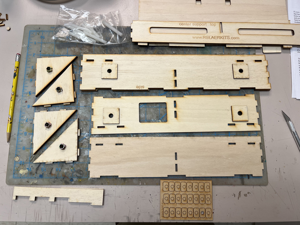
The back of the straight section needs to have a pair of reinforcement blocks glued to the inside face. These are required if you wish to add skyboards (backdrops) to your module later. Be sure the block clears the corner-brace slots below it.
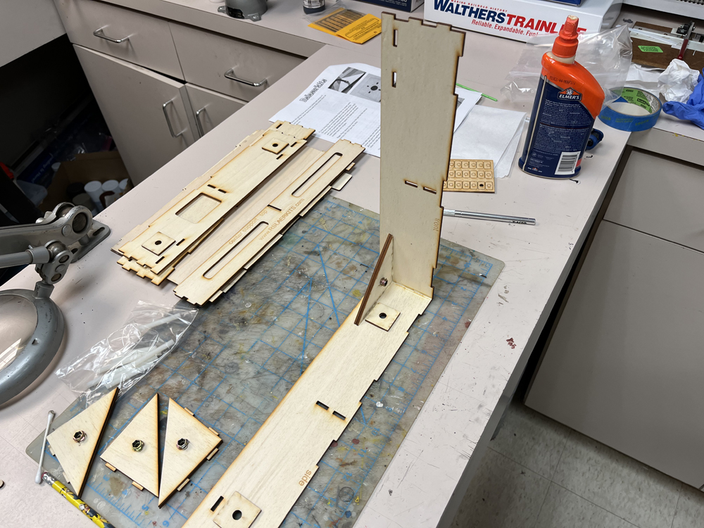
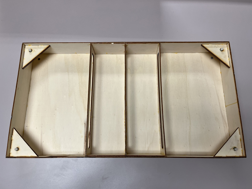
Taking one module side and one end section, apply glue to the interlocking corner tabs, as well as to the tabs on one corner brace. Plug all three parts into position. Note how the corner tab clears the reinforcing blocks on the back panel. Do the same for the second half. Make sure the parts fit flush and square, then let both module halves dry for about an hour before proceeding.
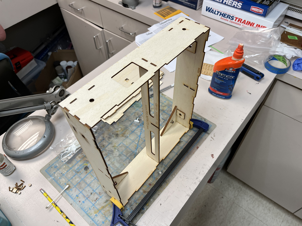
Next connect the two halves of the box together and glue their corner braces in place. At the same time, glue the center brace into the box. I found it was easier to slip it into place after I’d glued all sides of the box.
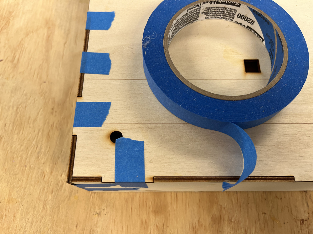
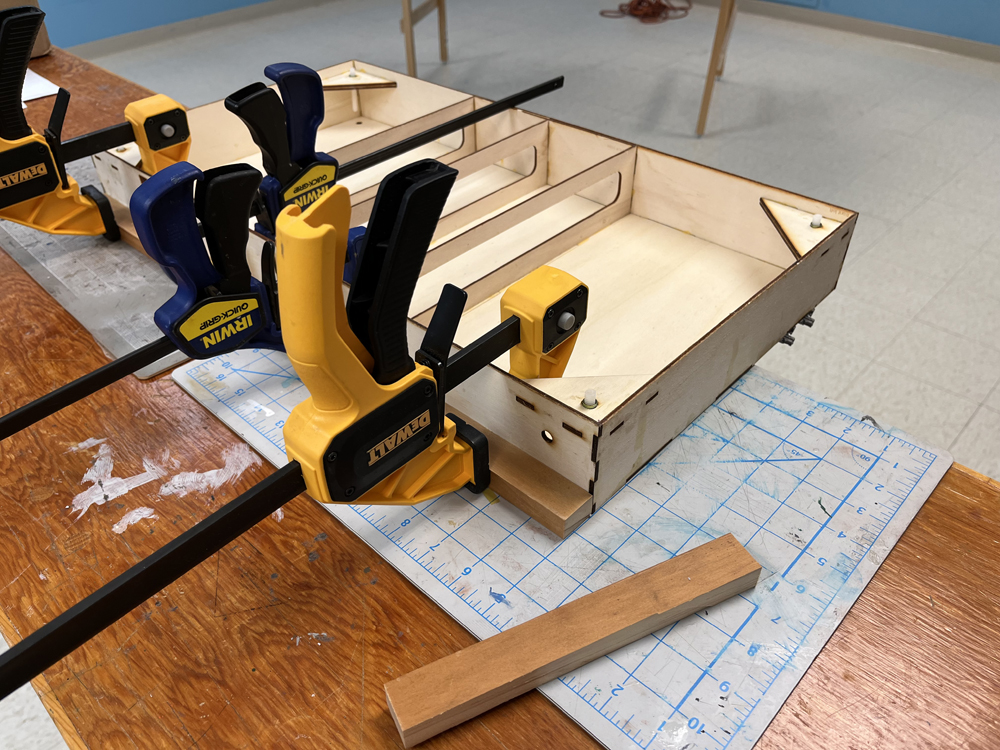
While the box frame is still gluing, install the two top boards, being sure to apply glue to all tabs on both parts. With the top in place, we used blue painter’s tape to keep the parts locked in tightly together and square. The technique worked better than clamps, which can deform the thin plywood parts.
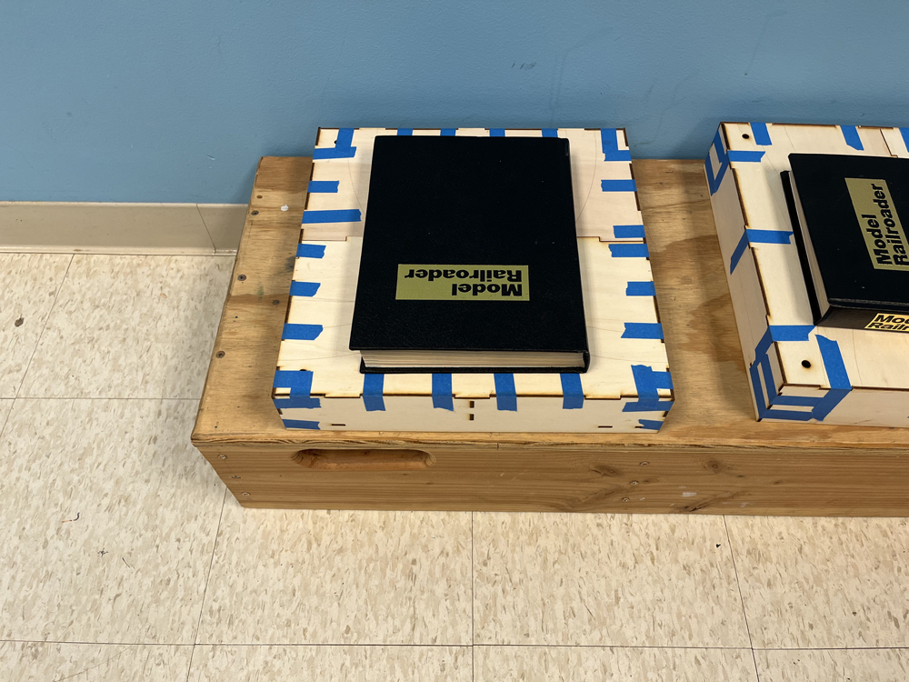
As we finished each module, we set a heavy book on it to keep the top from warping. We left the books and tape on the modules overnight to make sure the glue was completely set before removing them.
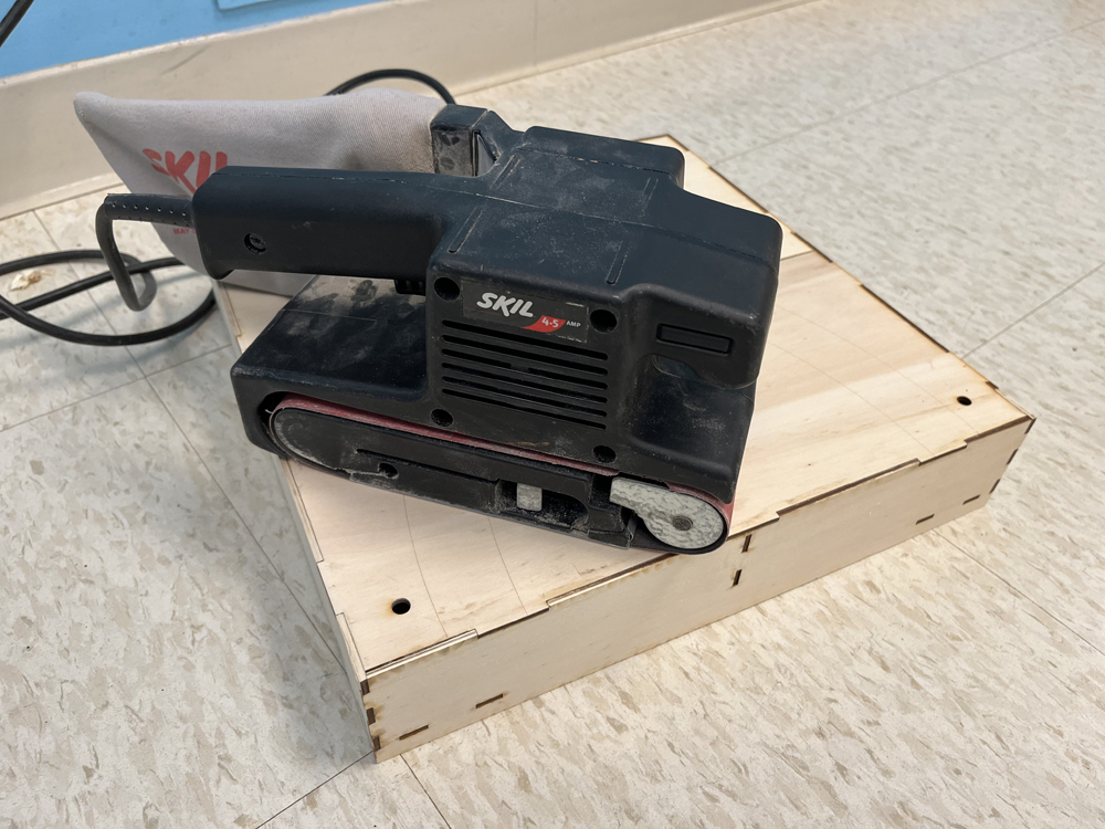
The next day, I sanded the tops of the modules so that the edges where the frame tabs connected were flush. I used a belt sander for this, but a regular block of wood and some sandpaper will work just as well. This is an important step as it will allow the track to lay completely flat.
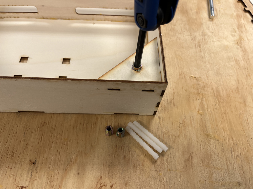
The kits include brass threaded nuts. One goes in the hole of each corner brace. You will need an Allen key for this part and be sure the nut goes into the hole straight.
Brian: If you didn’t line up the holes correctly when making the corner braces, the nut will go into the hole crooked.
David: But you can fix it by carefully enlarging the opening with a drill bit. Next, install the included nylon legs. These also have a small Allen head on one end, making them easy to install.
Brian: Can you adjust the nylon legs by using the holes in the top of the module?
Bryson: That would be great because you wouldn’t need to turn the finished module over to change the height of the legs.
David: The modules are designed with holes to allow foot adjustment from the top, which is why the nylon legs will accept an Allen wrench. I didn’t want holes in my finished scenery, so I installed the legs with the hex head facing downward. But if you want to keep the holes, then you can install the legs with the hex head facing upward.
Bryson: You are correct. These were pretty easy to build.
Brian: While my foam-top modules assembled the same as the basic straight module, I needed to make a few modifications to the process.
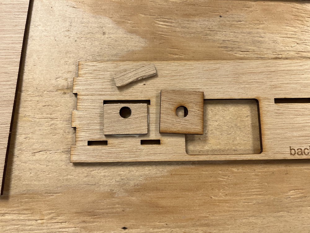
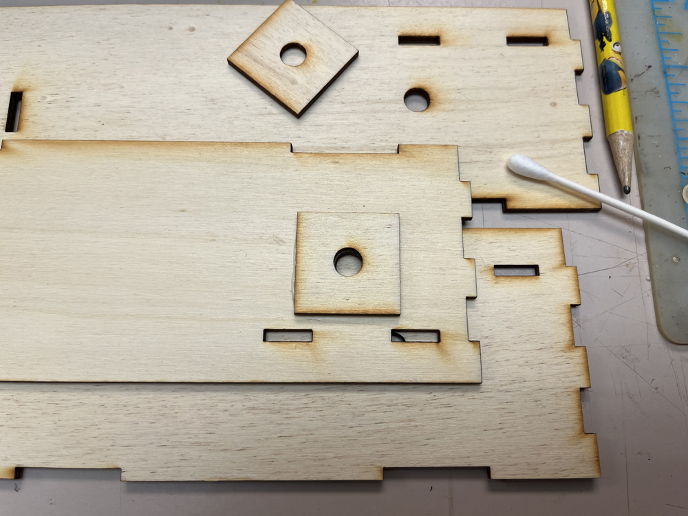
The corner braces glued together the same way, however the reinforcing blocks used to support the backdrop needed to be adjusted. Because these modules have a recessed plywood top, there are slots cut into the sides to support it at either 1” or 2” deep, depending upon the foam used. But because it’s a beta kit, it came with standard laser-cut reinforcing squares. To fit around the side slots I had to slice off ¼” from the top of the square as shown in the photo. I then glued them in place normally.
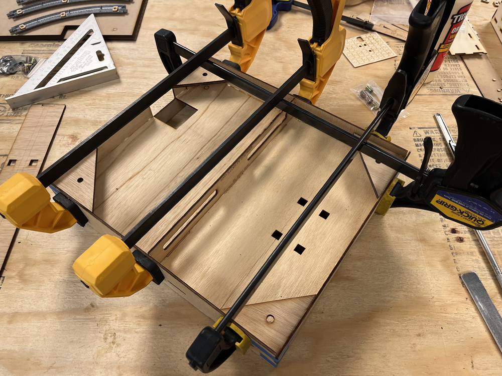
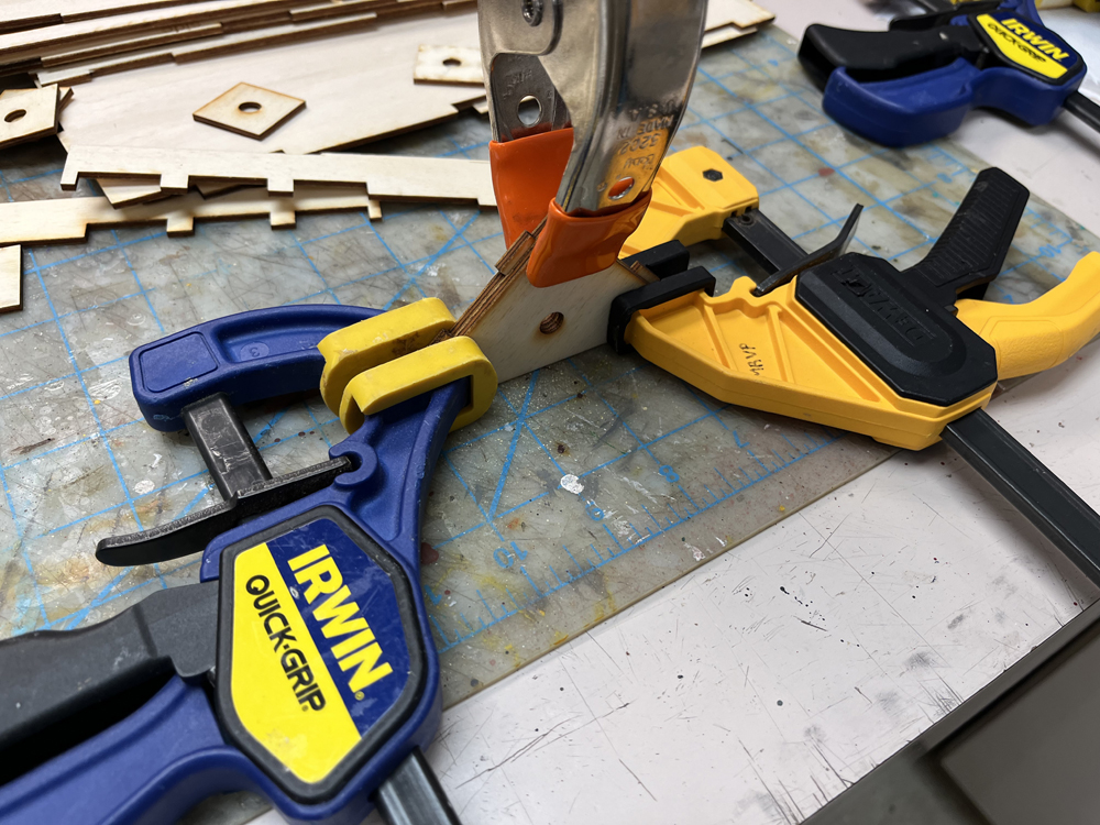
Speaking of gluing, because the top is not flush with the top of the frame, I couldn’t use masking tape to hold all the parts together. I used bar clamps instead, being careful not to apply too much pressure to avoid deforming the thin plywood pieces.
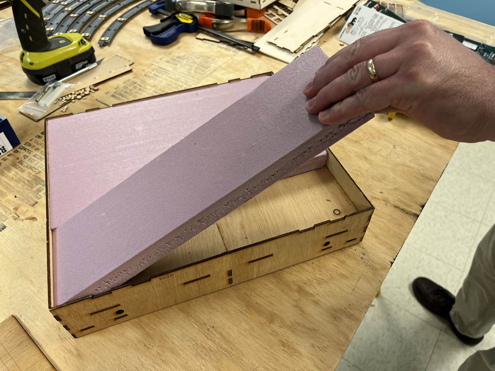
Once the glue dried, I cut 1” foam board sections to fit inside the box. For the 2” box, it was easier to use two layers of 1” foam than try to work with a full 2” block. When I know how the scenery will fit with the front edge of the module, I’ll then cut away the face to follow the contour of the ground.
Bryson: Ok, I can see how those are going to work. You could do some really neat things with your two modules.
Brian: I may put a small stream and culvert on one of them. I may also replace some of the 1” foam with ½” or ¾” foam to put a few houses in the background that are somewhat lower than the track.
David: Bryson, you built both a single straight and a double-straight module. How did the double differ from the single?
Bryson: The double proved to be a little more challenging than the single. Because of the limitations of Rich’s laser cutter, he couldn’t make full-length front and back pieces. Instead, before assembling the frame, I had to glue the front and backs together from multiple parts that connected with reinforcement plates. I let the glue on the front and back dry for an hour before continuing. Also, the top comes as three separate pieces, and not two like the single.
And it turns out that the double is also 1” shallower than the depth of the other singles. At first, I thought I’d leave it that way, but then David figured out we could just cut a 1 x 2 down to 1” wide and glue it to the back of the module.
David: This way all the modules are the same depth, so when we add backdrop boards, they will all line up.
Brian: Really? I thought you extended it because you needed a road to run behind Bryson’s grain elevator to get to your farm on the corner.
David: Bonus.
Bryson: And I didn’t mind because I wanted a road behind the elevator anyway, so this gave me enough space for it.
Brian: You know, with all the stuff we covered this time, we probably could have split part 2 into two parts all on its own.
Bryson: But now we’re done with building the basic modules. So, who’s up for track work?
Brian: The sooner we lay track, the sooner we can run trains.
David: Track work is a lot of work in itself, and we’ll cover that in the next T-TRAK installment.
Bryson: See you there!
Click here to read the next installment of the T-Trak project series!
Click here to read the previous installment of the T-Trak project series!