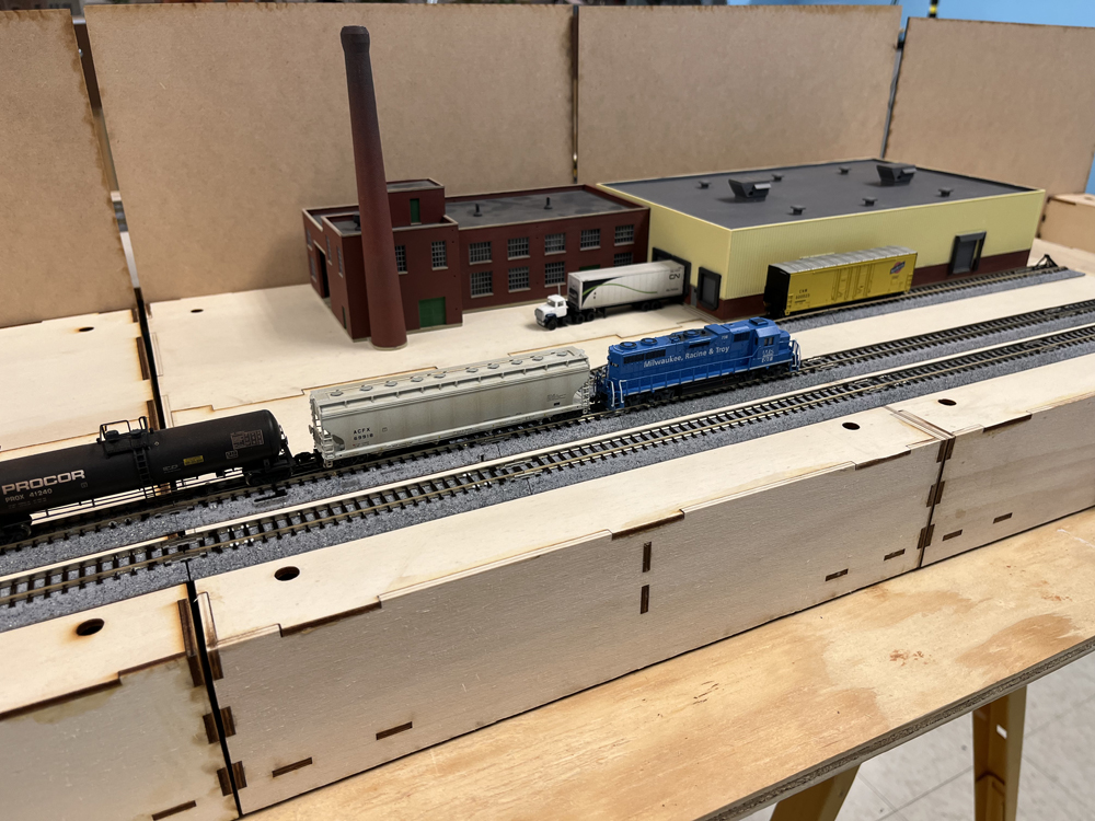
Modelers David Popp, Brian Schmidt, and Bryson Sleppy add Kato Unitrack to their modular T-TRAK N scale layout. T-TRAK is a modular N scale railroading system that uses foot-wide boxes plugged together to build tabletop layouts. In this third installment, the trio demonstrates how to build, wire, and install the Kato N scale Unitrack to the RS Laser module kits.
Brian: Bryson and I have been having so much fun working on David’s T-TRAK project that we’ve already ordered more module kits.
David: Wait, you’re already expanding? We haven’t even laid any track yet on the ones we have.
Bryson: We’re way ahead of you, chief!
Brian: Super Chief?
Bryson: I see what you did there. Nice! Well, after a trip to our local hobby shop (Hiawatha Hobbies) to pick up some track, I realized that I would prefer more space than a double module for my grain elevator.
Brian: And in addition to the two houses I’m planning to install on my modules, I also wanted to have a gas station or an auto repair shop too, so I needed at least one more.
David: While I’m glad you’re both having so much fun with this, we’re rapidly running out of table space for the finished layout.
Bryson: It’s modular, isn’t it? So, we’ll add another table!
Brian: Or two. (Laughs)
David: For today, the only thing we’re adding is the track.
Bryson: Hey, you wrote about this in your book, right?
Brian: So, Bryson and I think you should explain it here too.
David: Oh no. You two don’t get out of it that easy again. This is a group project, so welcome to the group, people.
Bryson: For now, though, our first challenge is getting the correct track on the correct module.
David: Fortunately, T-TRAK has figured all that out for us ahead of time. At ntrak.org, you can download the specifications for building T-TRAK modules, and it includes a complete list of Kato track materials needed for modules of each size.
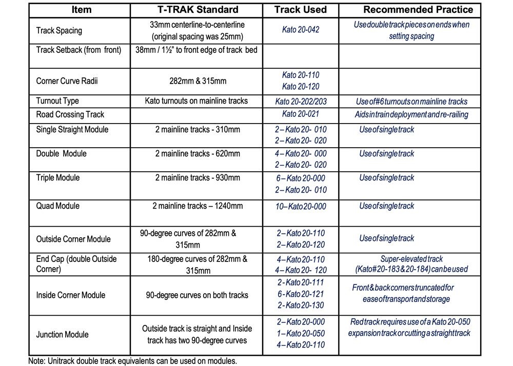
David: Since we have some basic straight and corner modules, we ended up using Kato 20-010 and 20-020 straights and 20-110 and 20-120 curve sections.
Bryson: The single straight modules use two each of the 20-010 and 20-020 sections, but the double straight uses fewer pieces if you use 4 Kato 20-000 and 2 no. 20-020 pieces.
Brian: The two of you also added turnouts, correct?
Bryson: Yes, since David and I both have modules with spurs and industries on them, we each picked up a Kato 20-220 no. 4 turnout for our double modules.
Brian: Doesn’t T-TRAK recommend using no. 6 turnouts?
David: It does if you are creating passing sidings or crossovers. However, since we are modeling switching spurs, the no. 4 turnouts fit better for us.
Bryson: The no. 4 turnout with a 62mm (20-040) straight section replaces one of the 186mm 20-010 straight tracks.
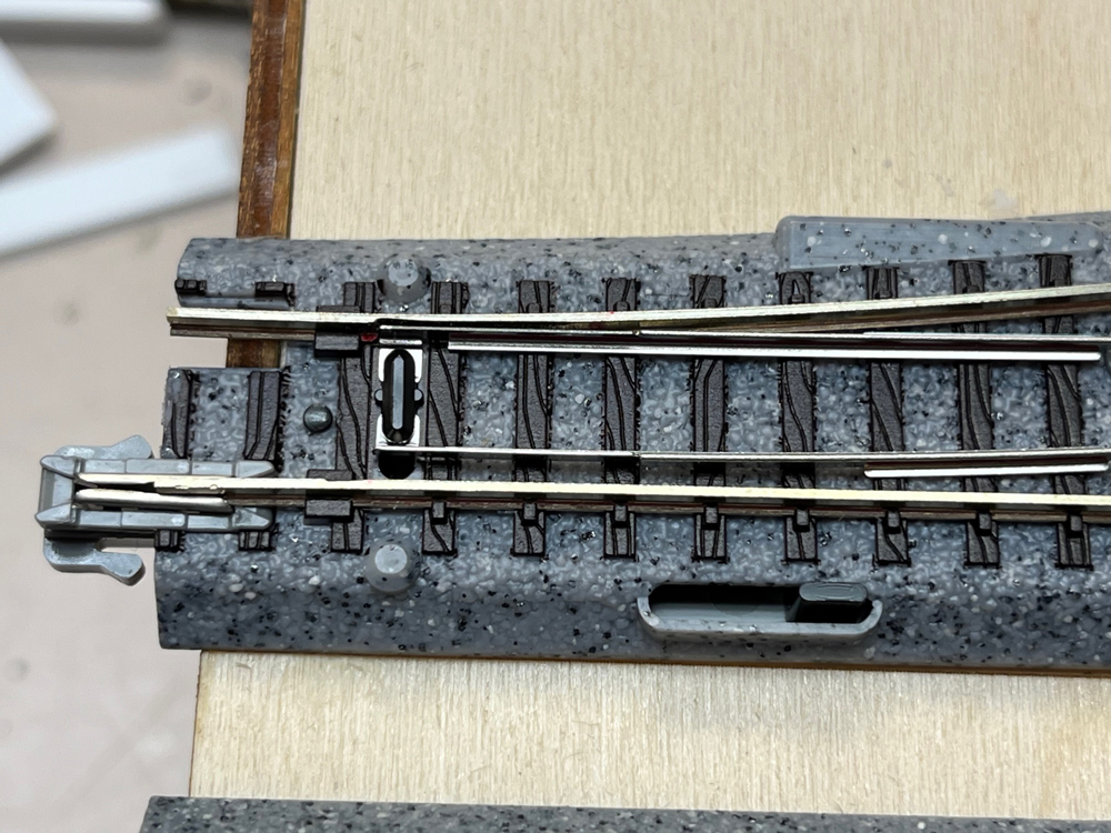
David: T-TRAK requires that you to modify the Kato no. 4 turnout slightly by filing away a bit of the head and foot of the rail, allowing the stamped-metal switch points fit flush.
Brian: This way trains rolling along the main line won’t pick the points with the wheel flange, correct?
Bryson: Correct. After marking the location of the switch points on the stock rail with a felt-tipped pen, David carefully pulled the rails partway out of the plastic roadbed and filed notches in the rails at those points.
David: After filing, I used a needle nosed pliers to pull the rails back into position. Use a pulling motion only. If you push them, the rails will easily buckle where you’ve filed the notches. You have to carefully guide the rail into the locking tabs on the plastic ties.
Bryson: The end result sees the point rails sitting in the notch where they won’t catch wheel flanges and cause derailments.
David: I’d recommend this modification on these turnouts even if you’re not building your layout to T-TRAK standards.
Brian: It makes sense. Less derailments equals more fun for everyone.
Brian: I’ll take the gluing track part. The RS Laser Kit modules includes a neat mounting tab for attaching the plastic track sections to the plywood. The kit includes a wood sheet of oval tabs. After punching them out of the sheet and clearing out the centers, you use wood glue to cement the tabs together in pairs, doubling their thickness.
Bryson: We used the same wood glue for this that we did to build the module kits.
David: But wood glue won’t attach the tabs to the slippery plastic roadbed, will it?
Brian: Nope. So, we used something more flexible. DAP Latex caulk works okay for this step. Flip a section of track over, apply caulk around the mounting posts, then press the doubled tabs in place. Be sure to let the caulk set over night before applying the track to the module.
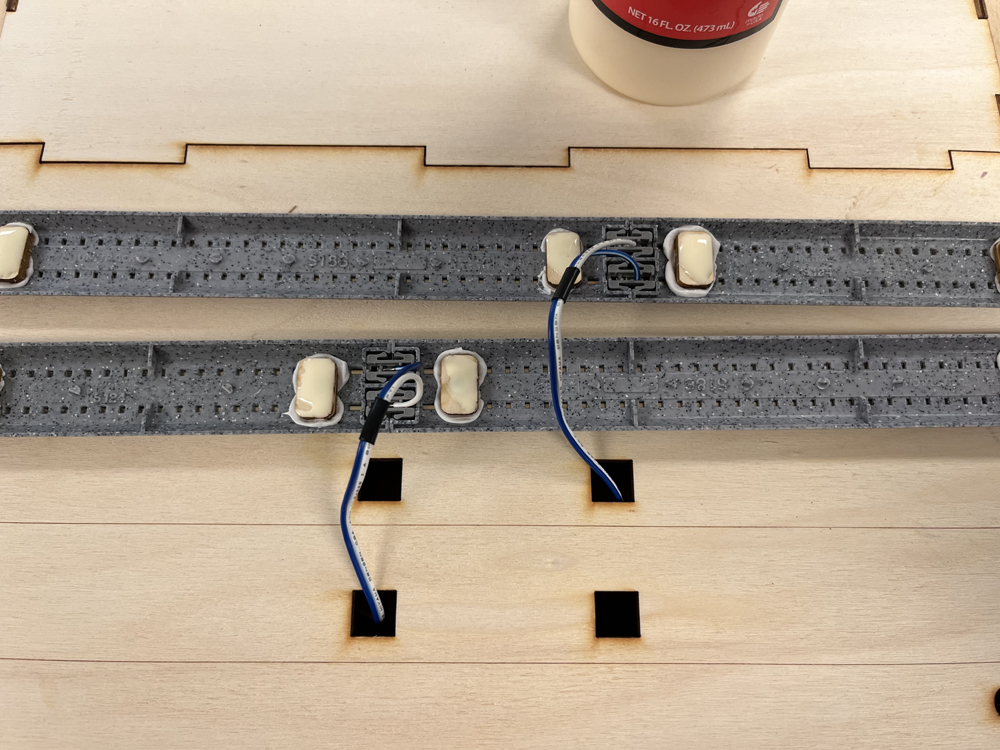
David: Even after the caulk set, we still weren’t quite ready to install the track. T-TRAK recommends feeder wires on all straight module sections. This is because the curved modules are larger, fit tightly together, and don’t leave any extra room to run feeder wires out the back.
Bryson: We used Kato 24-818 Terminal UniJoiners. Note that these are also used for Kato’s HO scale Unitrack pieces as well. The joiners come with a blue plastic tool used to remove the existing joiners on the track section.
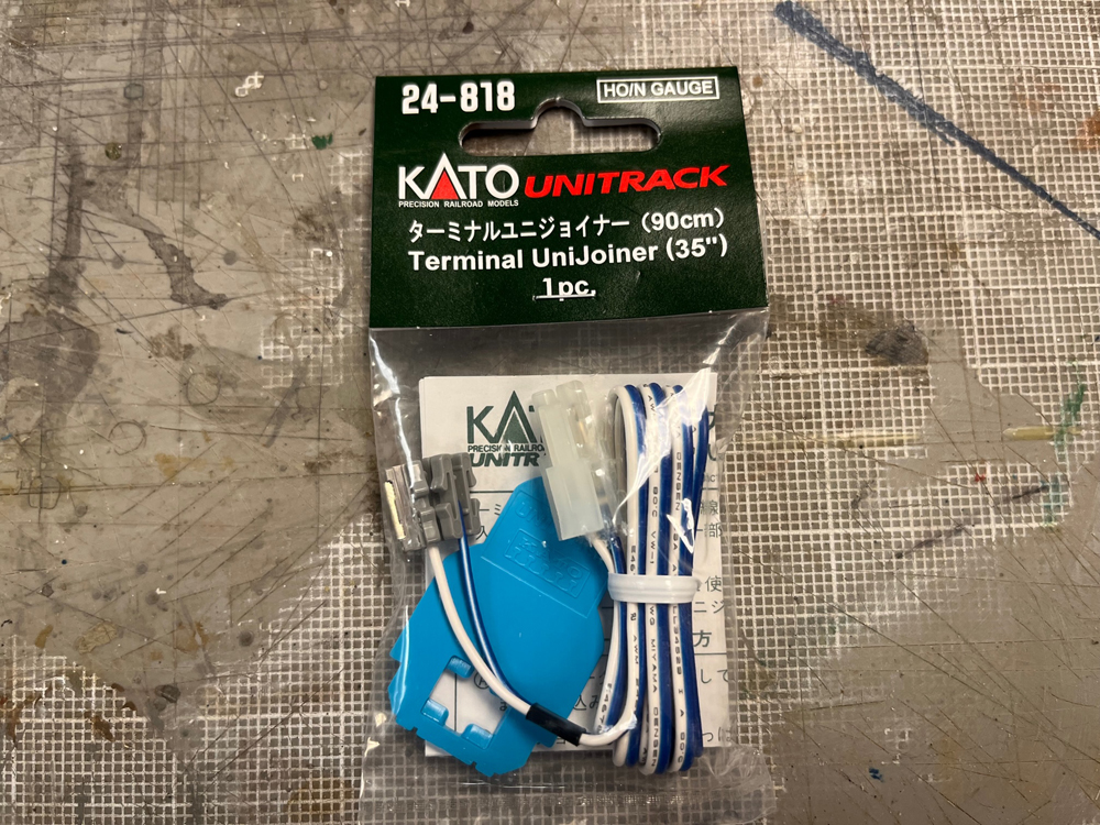
Brian: And while the disconnecting tool works okay, we actually got better results by squeezing the locking tabs with a fine-pointed needle nosed pliers.
Bryson: Either will work, and every pack of terminal UniJoiners comes with the tool, so if you don’t have the specialized tweezer-tipped pliers, you can still make the change (and end up with a lot of blue Unijoiner tools left over).
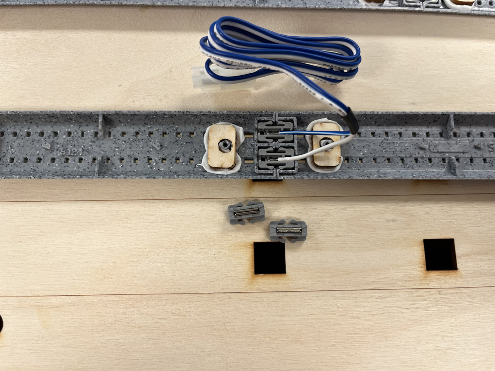
David: T-TRAK standards wire the feeders for the two main lines with opposite polarity. So, as long as you install the terminal UniJoiners with the blue wire on the outer rail of both mains, you will have the polarity correct.
Bryson: So, what do you do if you want to make your modules into a permanent layout and be able to pass trains from one main line to the other?
Brian: You could always wire both main lines the same way.
David: And if you still want to participate in T-TRAK clubs with some of your modules, you could just solder a power-reversing DPDT switch to the feeder that is opposite the wiring standard – just be sure to label the switch to avoid short circuits if it is set the wrong way.
Brian: Plus, the clubs keep the mains separate, so you won’t be able to use any modules that have a crossover on them anyway.
Bryson: Fair enough.
David: With the feeders installed, we then slipped the plugs and leads through the holes cut in the deck of the straight modules.
Bryson: RS-Laser kits provide two holes on each main line, so it will line up no matter which way you position your track. That was really handy for David and me as we had turnouts to fit into one of the main lines, so we needed the second set of holes.
Brian: We then applied wood glue to the tabs and positioned the track.
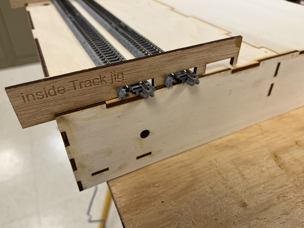
Brian: The kits include a pair of alignment guides for the ends, as well as scribed lines on the deck, making it easy to get everything to fit properly.
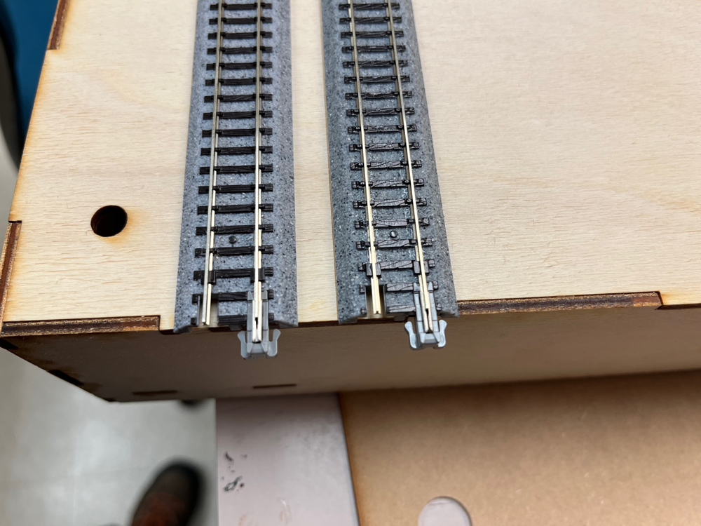
David: Speaking of fit, be sure that the Kato Unitrack is even at the ends and overhangs the module by at least 1mm. Otherwise it will be difficult to join and separate the modules. The locking tabs on the UniJoiners need a bit of wiggle room to properly connect.
Bryson: While the wood glue works for the wood tabs under the track, David and I had to use more caulk on the bottom of the turnouts as they are fully sealed with no place to put mounting tabs.
Brian: While all the mounting tabs worked as they should to keep the track aligned, after putting the modules together and taking them apart again, we noticed a bit of a problem.
Bryson: You’re calling the track coming loose a “bit of a problem?”
Brian: Okay, it was a major problem. The caulk didn’t stick to the slippery plastic roadbed well, and after some twisting, it tended to let go at the ends.
David: Fortunately, I’d already figured out a solution for this when we built the first set of T-TRAK modules years ago. On those, the track was glued to foam, which held even worse than the wood, so I added nailing blocks at the ends.
Bryson: Digging around the workshop, David came up with enough spare 1 x 2 to cut up enough 3” blocks so that each module could have one glued under both ends.
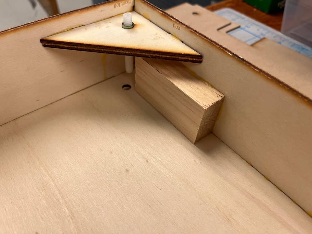
David: From there, Bryson and I simply measured the location of the nailing post on a spare piece of track and drilled an opening or a nail on the track sections already glued to the modules.
Brian: Atlas no. ATL2540 track nails did the rest. We installed them with a hammer and a nailset.
David: The track nails hold well, keeping the track from moving when plugging and unplugging modules.
Brian: Problem solved!
Bryson: Problem solved – now let’s run trains.
David: Great idea, but we’ve not assembled the power bus or installed a control system yet.
Brian: Which means more work ahead.
Bryson: Yup! More work ahead, but we’re getting close.
David: And we should be able to run trains by the end of the next installment.
Brian: Not to worry. Bryson and I have more modules to build yet!
Click here to read the next installment of the T-Trak project series!
Click here to read the previous installment of the T-Trak project series!