When I started in this hobby, I chose to model the early 1900s. That was before I knew what models were commercially available in my chosen time frame. (The answer was “not much.”) Since my hobby budget was limited, there was only one manufacturer making car kits appropriate for my era that I could afford. I won’t say who it was, but it rhymed with “Brown Mouse.”
One of the reasons these kits were affordable was that they were skimpy on the details. Horn-hook couplers I could upgrade, and molded-on grab irons I could either live with or painstakingly scrape off and replace with wire. But when it came to the underside of the cars, I was stumped. I figured there had to be more to a freight car’s brake system than the single molded Delrin detail part that came in the kit; I just didn’t know what it should be or where to get those parts. It didn’t bother me much, because I figured that if you’re seeing the bottom of your freight cars, you’re doing something wrong. But it still bugged me. Someday, I thought, I would find out what the underside of a boxcar should look like, buy a few packs of phosphor-bronze wire, and become a Real Modeler.
I never got around to that. I took a couple decades off from model railroading, and when I came back to the hobby, models were a much more detailed. “Brown Mouse” had been purchased by another manufacturer (rhymes with “Math Urn”) that was now selling those old cars as nicely decorated ready-to-run models. But they still didn’t have the same great brake gear detail as other “Math Urn” cars. The components were there, but what did they do? Where did the brake rods go? What about the air pipes?
If you’ve got a bunch of cars on your layout in need of brake gear, like I do, and you want to know the difference between K and AB brakes, what the levers and rods do, and how to rig them, I’ll brake it down for you. (See what I did there?)
Before the turn of the last century, most cars had only manual brakes. Since they had to be applied by a brakeman turning a wheel on top of the car, they served mainly as parking brakes, to hold a spotted car in place. If a coupler released accidentally or broke, separating a car or a string of them from the locomotive, there was no way to apply the car brakes and stop the runaway cars unless the brakeman happened to be on board.
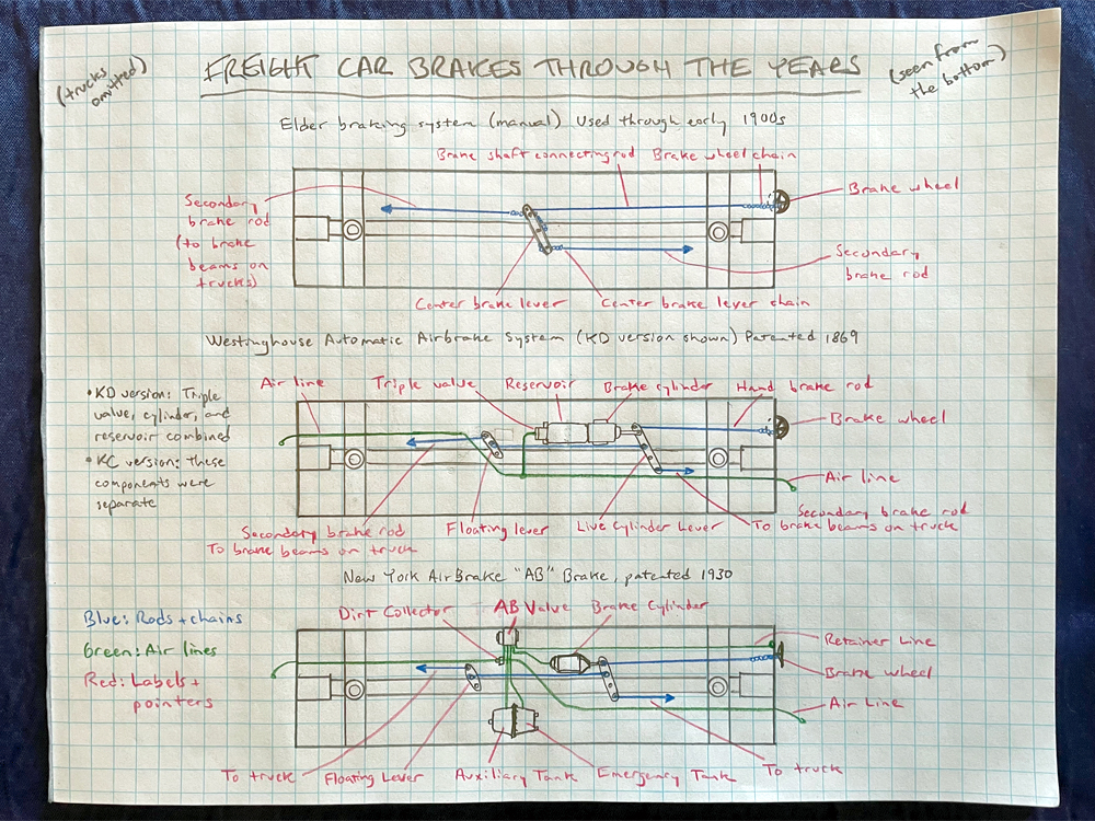
The Elder braking system, a typical example of a manual brake, is shown in the top diagram of my sketch. Turning the brake wheel would spin the brake staff, winding the brake wheel chain around it. This would pull on one end of the center brake lever, which pivoted in the middle. A chain wound through this lever would then pull on the secondary brake rods, which activated an assembly of levers that pressed brake shoes against the wheels. (For clarity, I didn’t draw the trucks or their brake beams, since those parts usually come already modeled on trucks.)
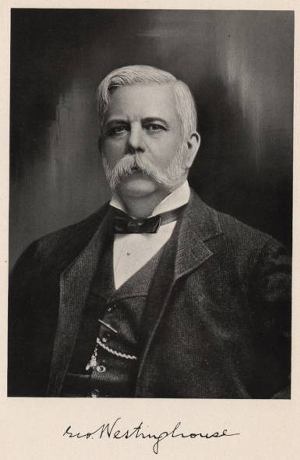
In 1869, George Westinghouse founded the Westinghouse Air Brake Co., often abbreviated WABCO, and invented what was known as the “straight air brake.” These relied on positive air pressure from a reservoir on the locomotive to apply the car brakes. This meant that brakes on cars closest to the reservoir would be applied first, so slack action was a problem for cars farther back in the train. What’s more, if a car separated from the locomotive, there was no way to apply the brakes – the same problem manual brakes had.
In 1873 came the development of the automatic air brake. This system was safer than the straight air brake because it equipped each car with its own air reservoir and triple valve. The triple valve was so called because it performed three functions: it allowed air from the train line to fill the car reservoir; it applied the brakes; and it released the brakes. If the air pressure in the train line was higher than in the reservoir, it would fill the reservoir and release the air in the brake cylinder. If air pressure in the train line dropped lower than in the reservoir, air would be routed from the reservoir to the brake cylinder, stopping the car. When the pressure was equal, all valves would close, keeping pressure in the reservoir and not pressurizing the cylinder.
Early automatic air brake systems are known as “K brakes,” after the type of triple valve. The middle diagram on my sketch shows a typical rigging for a boxcar equipped with the KD system, in which the triple valve, reservoir, and brake cylinder were a single assembly. (This is the detail part you’ll find under the car floor of those Brown Mouse cars.) Later, the KC system was developed, in which these three components were mounted separately and connected with air lines. The K valve was removed from the Federal Railway Administration’s list of approved equipment for cars in interchange service in the 1940s.
After World War I, the railroads started looking for a replacement for Westinghouse’s venerable K valve. The result was the AB valve, developed jointly by Westinghouse and New York Air Brake (NYAB) and adopted by the Association of American Railroads in 1934. The AB braking system added more safety with a two-part reservoir consisting of an auxiliary tank and an emergency tank. If you have a detail part of a tapered tank with a bolted ring around the middle, that’s an AB double reservoir. A typical AB brake rigging arrangement is shown in my third sketch (at bottom).
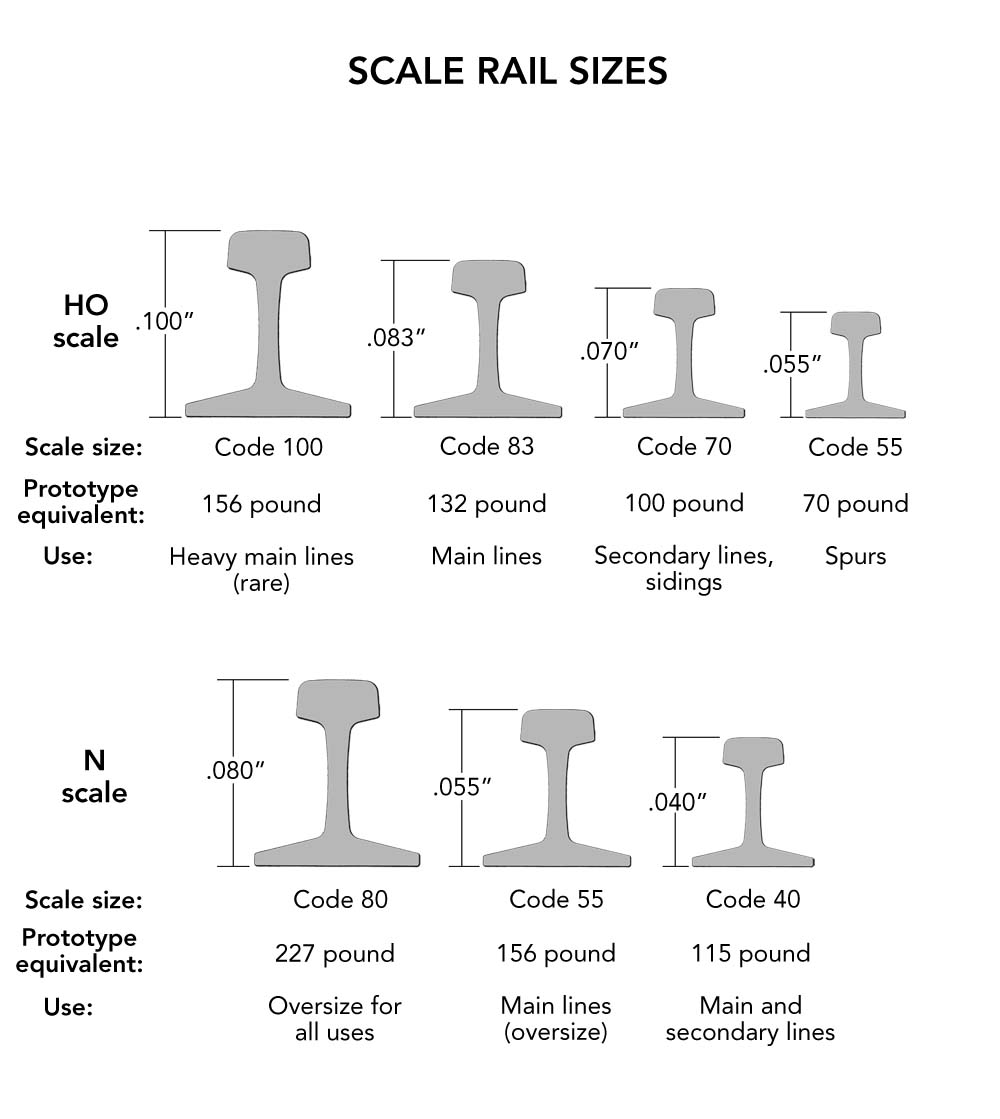
The steel rods in car brake systems range from 7/8” to 1¼” outside diameter (OD). In HO scale, you could model that with .01” to .015” brass or phosphor-bronze wire. If you model in N scale, .006” to .008” diameter would work; for O scale, .018” to .026” will do the trick.
The various levers can be easily fabricated from strip brass or styrene. Brake cylinder levers range from 3 to 4 feet long, while floating levers are 2-1/2 to 3 feet long. Both taper from about 6 to 8 inches across the middle to 2 or 3 inches wide at the ends.
The air lines in a typical car brake system call for a variety of wire thicknesses. The train line typically has a 1¼” OD; that’s approximately .008” in N scale, .015” in HO, and .026” for O. The retainer line used in AB brakes is typically 3/8” OD. You can get wire that thin in O scale (.008” would work), but you’ll have to make do with .006” in HO and N scales. The other air lines connecting cylinders, valves, and reservoirs are usually ¾” OD. This translates to .008” in HO scale and .015” in O; you’ll have to use .006” in N scale.
Of course, wire at these small diameters can be very delicate. You might decide that durability is more important than scale fidelity and opt for thicker wire for your brake gear, especially in smaller scales. Detail Associates, K&S Engineering, Tichy Train Group, and other manufacturers sell brass, steel, and phosphor bronze wire and strips to the hobby market; you can buy them from your local hobby store or through Wm. K. Walthers.
The National Model Railroad Association (NMRA) has a downloadable data sheet with a wealth of information about car brake systems. You can download it from the NMRA’s website.
Interested in learning more about the key components of a freight car? Click here!