Railroads & Locomotives History Deciphering the Baldwin Locomotive Works classification system

Deciphering the Baldwin Locomotive Works classification system

By Kurt Bell | March 9, 2021

| Last updated on March 10, 2021

Complicated alpha-numeric system is often the only way to identify certain locomotives

Email Newsletter

Get the newest photos, videos, stories, and more from Trains.com brands. Sign-up for email today!

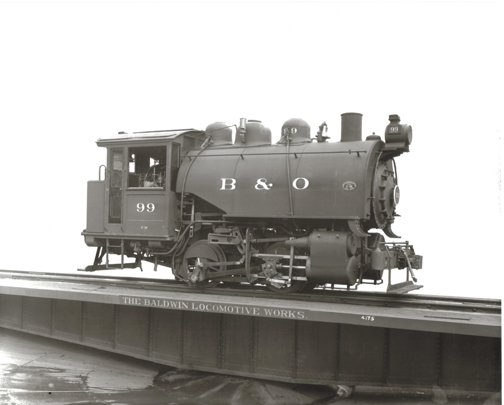
Baldwin 0-4-0T built for the Baltimore & Ohio in 1912.
This 0-4-0T switcher for the Baltimore & Ohio was photographed on November 21, 1912. This type of engine was dubbed a “Dockside” switcher and was later produced in the thousands as a popular HO scale model railroad engine adored by adults and children worldwide. Baldwin Locomotive Works photograph

History of the Baldwin classification system

The Baldwin classification system originated in 1842, when Asa Whitney was a partner of M.W. Baldwin and continued in use until 1938.

Baldwin builder’s photo of 2-6-0 from 1925, used on a photo specification card.
One example of almost 13,000 Baldwin Locomotive Works Photo Specification Cards. Baldwin Photo.

The system was based on use of a letter to designate the number of pairs of driving wheels on a steam locomotive. The letter A designated a special class of high-speed geared locomotive, also a rack or cog locomotive with a single pinion, etc., of special design, with one pair of driving wheels; B, a locomotive of conventional design, also with one pair of drivers; C, a locomotive with two pairs of drivers (4-4-0 or 0-4-0T); D, one with three pairs (2-6-0, 4-6-0); E, one with four pairs (2-8-0 or 2-8-2) or F, with five pairs (2-10-0 or 4-10-0). The total weight of the locomotive in long tons was also given. thus: 12-ton C, 18-ton D, 20-ton E, etc. Later, the total number of wheels was also designated, as: 24-ton 8-wheel C, 34-ton 10-wheel E, etc. For Mallets or articulated locomotives Baldwin used two

Locomotive classification and specifications from a Baldwin Photo Specification card, for a 2-6-0 built in 1925.
The reverse side of the Photo Specification Card above, which typically contained a summary of the engine’s mechanical data. Information on an engine’s boiler, driving wheels, engine truck wheels, wheel base, weight and tender statistics were summarized, as well as the negative number of the engine shown on the front side of the card. Note the classification number (8-30-D), as explained in the text. Baldwin Photo.

letters in the fourth place, one for each pair of driving wheels, for instance C-C (e.g., 0-4-4-0) or D-D (used for an 0-6-6-0).

Up until the Civil War there was a fairly close relationship for each general type of locomotive between its weight and the size of its cylinders. As the types of locomotives became more diversified, this relationship began to disappear. About 1873, it was decided that the number formerly representing the weight should represent the cylinder diameter. Dividing this number by 2, and adding 3, gave in most cases the actual diameter of the cylinders in inches. With the introduction of locomotive types having a truck at each end, or a truck at the back only, a fraction was introduced to indicate this fact.

Baldwin classification example

The class number for the Nevada-California-Oregon Railway 4-6-0 No. 8 built by Baldwin in 1903 can be described in the following manner:

10-24-D 35
— 10 indicates a total of 10 wheels (note that the tender is not considered part of the wheel count);
— 24 represents the size of the cylinder (the engine has a 15-inch bore cylinder. They used 24 because 24 divided by 2 = 12, plus 3 = 15, or in reverse, 15 – 3 = 12 x 2 = 24); Make sense?
— D = 3 pair of driving wheels, the first element sorting class numbers;
— 35 indicates the 35th locomotive to be built consecutively in the class. Such items as cabs, stacks, domes, smokeboxes, paint and trim varied on locomotives within the same class but they had no bearing on the class number.

Trailing and leading trucks

With the introduction of locomotive types having a truck at each end, or a truck at the back only, a fraction was adopted as the third number set, such as 10-26 ¼-E, whereupon ¼ represented the presence of both front and trailing trucks (e.g., 2-8-2 of class 12-26 ¼ E), or 10-26 1/3-E, with 1/3 indicating the presence of the trailing truck only (e.g., 0-4-2 of 06-22 1/3 C) OR front trucks only or is without trucks (e.g., 2-8-0 or 0-6-0). Whenever ½ was used, it indicated a special order with some mechanical differences—either minor or major—from the rest of the class, such as 06-12 D ordered with changes and becoming an 06-12 ½ C. If a truck was used at each end, and the rear truck had two pairs of wheels, the fraction was 2/4 instead of ¼. This change was made about 1928.

High and low pressure cylinders

Around 1900, the Baldwin class number became even more complex with the introduction of fractions to designate the high and low-pressure cylinder diameters of a compound or duplex locomotives. A Union Pacific compound of 1902 was a 10 25/46 E. The middle two numbers referenced the bore of the front cylinders (25) and rear cylinders (46), but sometimes an arbitrary number was used to denote sizes. For example, 42/66 represents a compound engine with cylinders of 21 and 33 inches front to rear (42 divided by two plus 3 equals a 24 inch diameter for front cylinders and 66 divided by 2 plus 3 equals 36 inch diameter rear cylinders).

In the case of two small classes of narrow gauge locomotives, the fraction ½ was introduced to indicate a long piston stroke. Class 8-18-C had 12-inch-by-16-inch cylinders and Class 8-18 ½-C, 12-inch-by-18-inch cylinders, whereas class 10-24-E had 15-inch-by-18-inch cylinders, and class 10-24 ½-E, 15-inch-by-20-inch.

When the Pennsylvania Railroad standard locomotives were built, they were designated class 29 ½-ton 10-wheel D; and later as class 10-29 ½-D, although they had cylinders 18 inches in diameter.

Baldwin classification for electric locomotives

On electric class locomotives (indicated as the third sequential number), the following codes would apply: 4 = 4 wheels; 2 = 2 motors; 50 = 50 HP each motor; C= 4 driving wheels, D= three pairs and E = four pairs of driven wheels; 123+ number of units built. For instance, 6-24 D would be an 0-6-0 electric “switcher.” In the case of 8 2/100 C, the number of wheels including unpowered axles is (8), the number of motors is (2) and the horsepower per motor is (100); C indicates the total number of wheels (4) driven directly by motors.

Baldwin builder’s portrait of Santa Fe 4-6-4 No. 3465.
This photo of Atchison, Topeka & Santa Fe 4-6-4 No. 3465, shown at Baldwin’s Eddystone plant on Nov. 15, 1937, is a typical builder’s portrait. Note the negative number inscribed in the right foreground, using opaque solution. Baldwin Photo.

Replacing Baldwin classification

Baldwin adopted a new method of classifying locomotives in 1939, using the Whyte System of Locomotive Classification. The change saw the addition of a number to indicate the actual cylinder diameter and the letter S to indicate steam. Thus, a locomotive formerly 16-48-2/4-E 30 became 4-8-4-27-S 30. C&O No. 1309 would be included in this changeover as it was built late in the steam era.

These guidelines can be used by railroad historians to distill the mystery of Baldwin’s complex classification system, which often is the only reference to a particular engine in the company’s surviving records. Often this classification number was stamped on locomotive appurtenances, such as connecting rods and boilers, for ordering replacement parts by owners.

Sources: MG-427 Baldwin-Hamilton Collection, Mallory Hope Ferrell, James W. Alves, and Paul T. Warner.

You must login to submit a comment