


Mounting styrene spacers
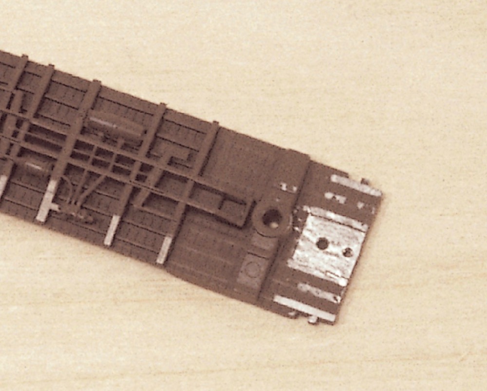
A Micro-Trains Line boxcar is the easiest car to convert to Z scale couplers. First, I remove the body from the frame. Then I flip the frame upside down and take off the trucks and stirrup steps. At each end of the frame are the coupler mounting pads. Each pad has two holes drilled through it. For a Z scale coupler, I use the hole closest to the end, as shown in fig. 1. I add styrene spacers to each pad to bring the smaller couplers to the correct height.
I make spacers by cutting 1⁄4″ lengths from .020″ x .156″ strip styrene. After using a sanding stick to remove the paint from the coupler pad, I attach the spacer over the pad with thick cyanoacrylate adhesive (CA). Once the glue sets, I flip the frame right side up.
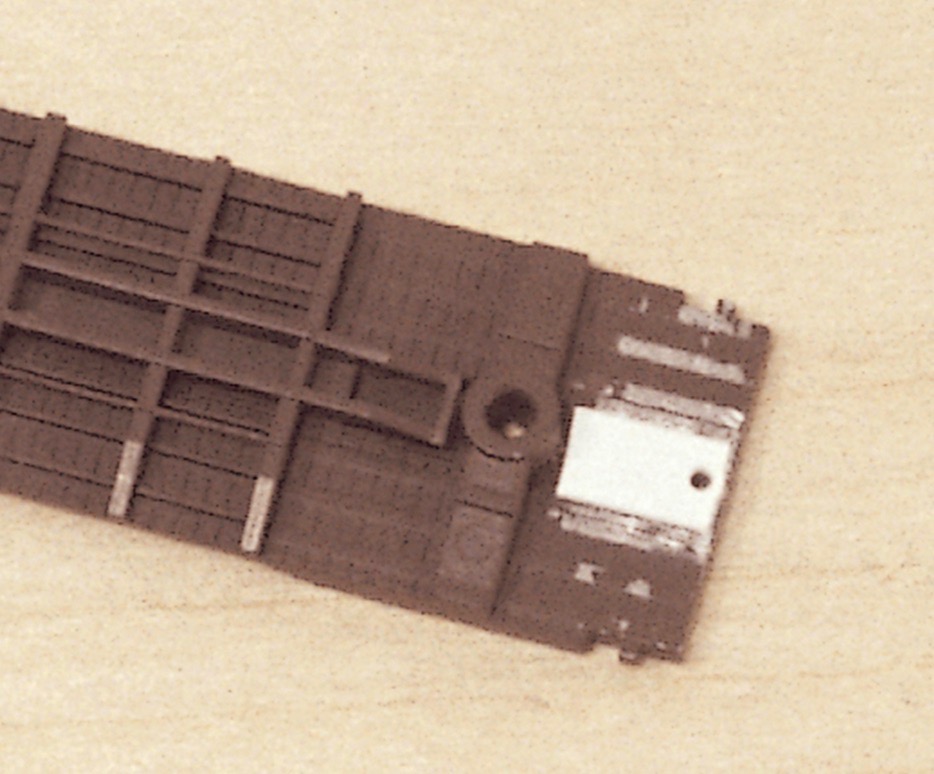
Using a no. 56 bit in a pin vise, I drill down through the existing mounting hole and the styrene spacer. Then I cut the screw threads using a 00-90 tap in my pin vise. I remove excess material around the lip of the hole with a hobby knife. The new mounting hole is shown in fig. 2.
A variation for fragile frames
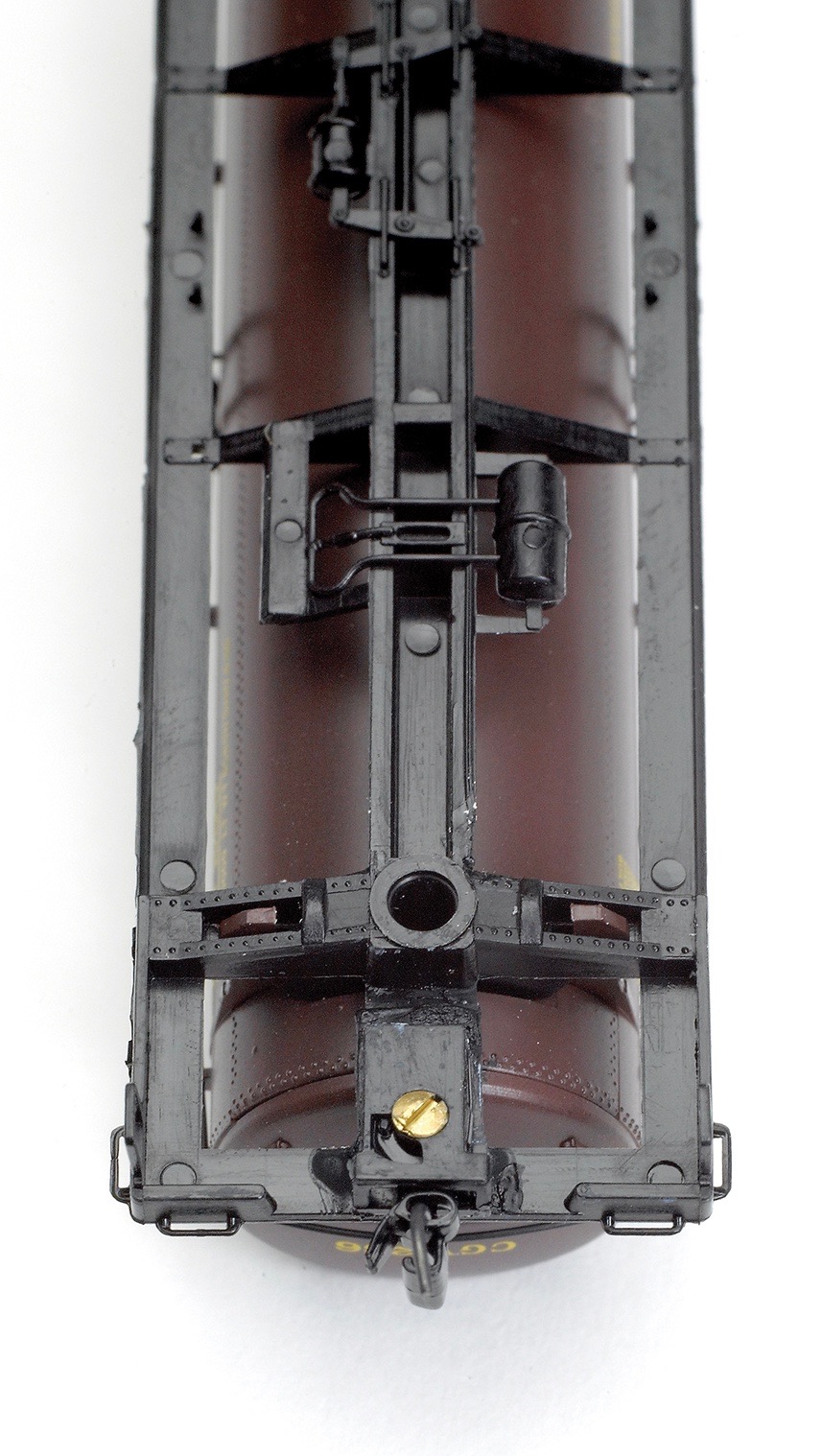
For cars without a solid, flat frame, such as hoppers and tank cars, you’ll need to drill and tap the spacers before gluing them to the coupler pads. I make spacers from the same styrene strips as for the boxcar. Holding the spacer next to the coupler pad, I mark the hole location on the spacer with a pencil.
After drilling the hole, I glue the spacer to the coupler pad. I stick a push pin through the hole to align the spacer. Once the glue has dried I tap threads through the hole.
Both the N scale boxcar (Fig. 3a) and tank car (Fig. 3b) have had their original couplers replaced with Z scale couplers.
Installing the couplers
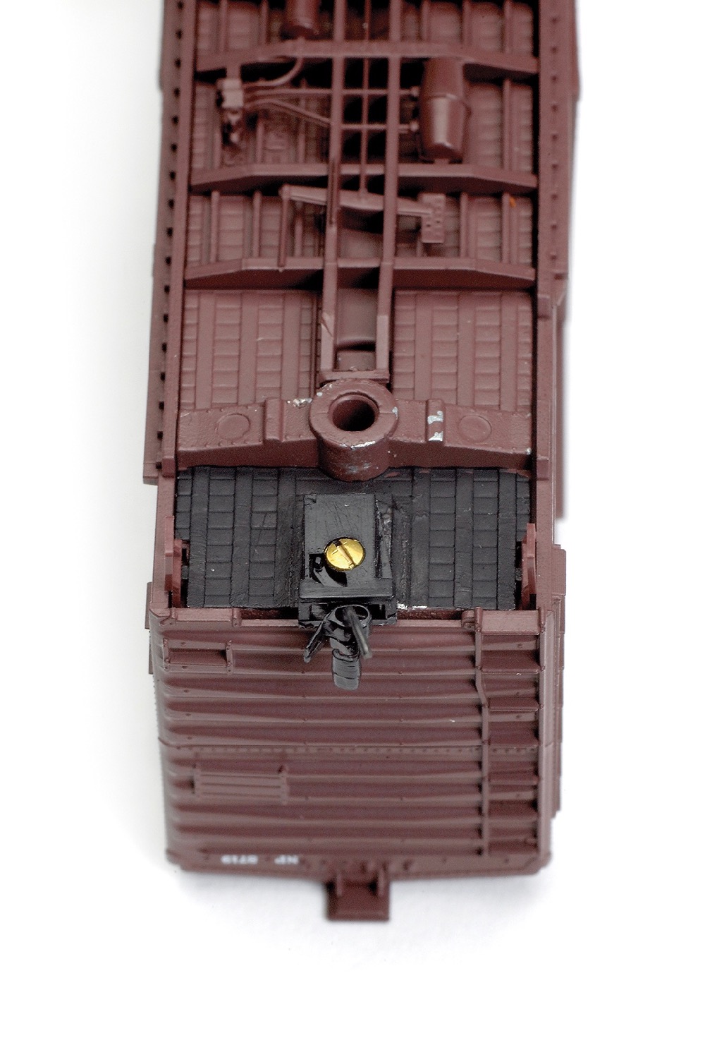
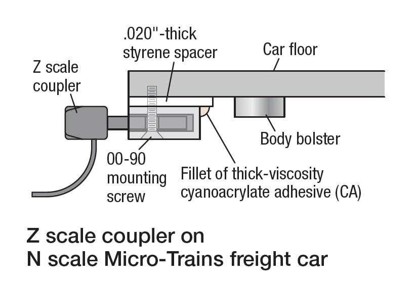
To mount each coupler, I use a 00-90 screw as shown in the drawing. Proper screw tension is critical for reliable coupler operation. If the screw is too loose, the coupler will swivel out of position. If the screw is too tight, it will crimp the coupler box, and the coupler will bind.
To check for proper screw tension, flick the side of the installed coupler with your finger. The coupler should return to center. If it doesn’t, adjust the screw tension accordingly.
To keep the coupler assembly centered, I spread a drop of thick CA into a fillet between the back of the coupler box and the spacer. I don’t use thin CA, since its consistency and quick drying time make it hard to control. I don’t want to get any glue on the coupler’s moving parts.
Finishing touches
To finish the installation, using a very fine brush, I paint the spacers with flat black paint. As with glue, it’s crucial not to get any paint inside the coupler mechanism. Because I wanted a secure glue bond between the styrene spacers and the coupler boxes, I didn’t paint the spacers before assembly. See fig. 3 for examples of completed Z scale coupler conversions.
After installing the couplers, I reassemble the car. Before reinstalling the trucks, I cut off their old truck-mounted couplers with a hobby knife and replace their original oversize-flange wheelsets with Micro-Trains low-profile wheels.
Also for a more prototypical appearance, I trim off most of the couplers’ wire “glad hands,” leaving just enough material to hold the coupler halves together. I don’t use magnetic uncouplers; operators on my layout manually un-couple cars with bamboo skewers.
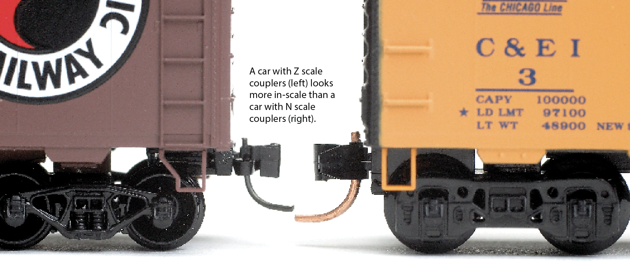
A few puffs of dry lubricant on the front and sides of the couplers and this project is complete. Properly installed Z scale couplers link up reliably with N scale couplers, so I don’t have to convert my entire fleet all at once.
My freight cars that I’ve converted to Z scale couplers operate as reliably as my freight cars that still have N scale couplers. And though the new couplers are quite small, my switch crews have commented that uncoupling moves are easier with my rolling stock than with many HO scale cars.
Lance Mindheim has written several articles for Model Railroader and Model Railroad Planning. He owns a custom-layout-building business. This article was originally published in 2007.


How about using N-scale couplers on HO rolling stock? Has anyone tested?
Thanks for comments!
/Erik
I note you wrote that you cut off most of the trip pin since you don’t use uncoupler tracks. For those of us who do, I imagine assembly would require straightening the pin’s arc until the bottom is below the spacing requirement, then bending just the last 1/16~1/8 in of the tip up to horizontal at that required height. Steady hands and more than one tool are needed at the same time while the coupler assembly is carefully immobilized. Also, how well does the Z coupler link to other N couplers or does this require a mission to change all the couplers?