


Solder track feeder wires: Good feeder wires are an important part of building a reliable model railroad. Feeders are the small wires that connect the track to a layout’s power bus and ultimately to its control system. Whether you are using AC, DC, or Digital Command Control (DCC) to run your trains, you will need feeder wires.
In the examples shown here, I used 22-gauge wire to make feeders for my On30 model railroad. Gauge in this case indicates the diameter of the wire. When using the American Wire Gauge (AWG), the larger the number, the smaller the diameter of the wire.
The gauge of the wire you use will depend a lot upon the scale and the height of the rail you have chosen for your layout. For N scale track, 22-24-gauge wire is appropriate. HO and On30 typically use similar sizes of rail and work well with 20-22-gauge wire. Larger scales, such as O, should use 18-20-gauge wire.
Small-gauge feeders are reliable only over short distances before they encounter a significant voltage drop. I like to keep my feeders to a length of 12” or less, tying them into the heavier 14- or 16-gauge wire used for power buses. For more on wiring layout bus lines and feeders, watch my video, DCC installation for large layouts part 1 – bus lines.
Following are the 10 steps I use to make simple, reliable feeders and solder them to the rail. You can apply the technique to virtually any scale by changing the size of the wire. (Note: on large-scale track, you will want to switch to a resistance soldering tool. A standard soldering iron will take too long to heat larger codes of rail.)
Step 1 – Gauge and color code
My On30 layout uses code 100 rail. For feeder wires on this type of track, I selected 22-gauge, solid bell wire. This type of wire is readily available at home centers and hardware stores. It usually comes in white and red, so those are the colors I use for my track power bus as well. To keep straight which feeder goes to which rail, I use the color code “white out.” This means the white feeder always goes to the outside rail – the one that faces the aisle in the layout room.
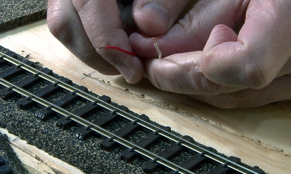
Step 2 – Flatten the tip
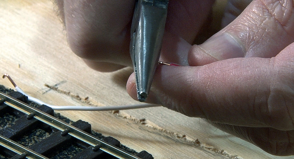
After stripping the wire, I crush the tip flat using a pair of needle nose pliers with a smooth jaw. Insert the tip of the wire into the pliers, close the jaw, and apply firm pressure.
Step 3 – Make a 90-degree bend
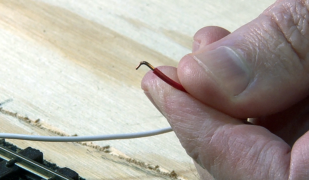
With the tip flattened, I then make a small 90-degree bend in the wire to form an L shape. This will allow the feeder to connect to the track from a hole positioned next to the rail.
Step 4 – Drill holes
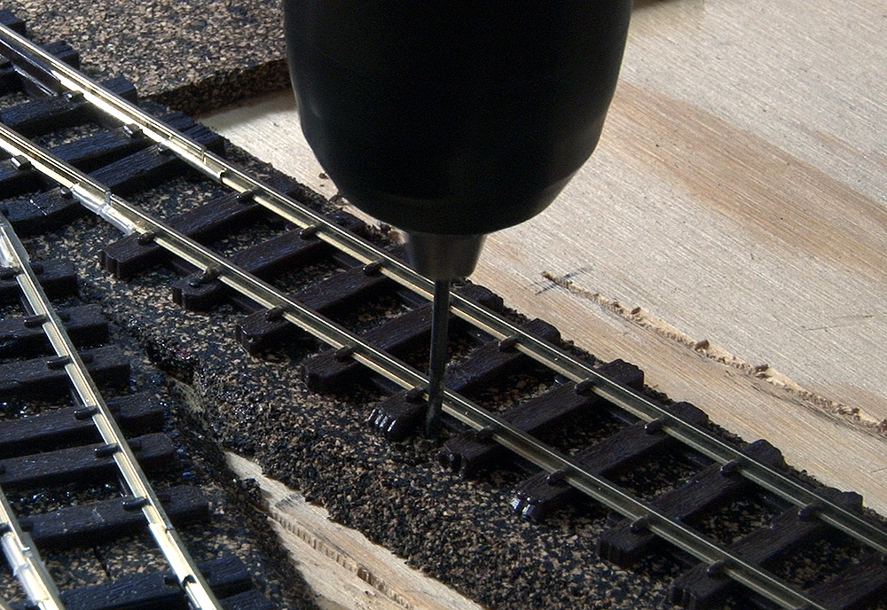
I select a drill bit for the feeders that is slightly larger than the gauge of the wire I make them out of. Having a hole that is a bit larger than the feeder will allow it to be positioned easily, but also will hold the wire casing enough to keep the feeder next to the rail for soldering.
Step 5 – Positioning the feeder
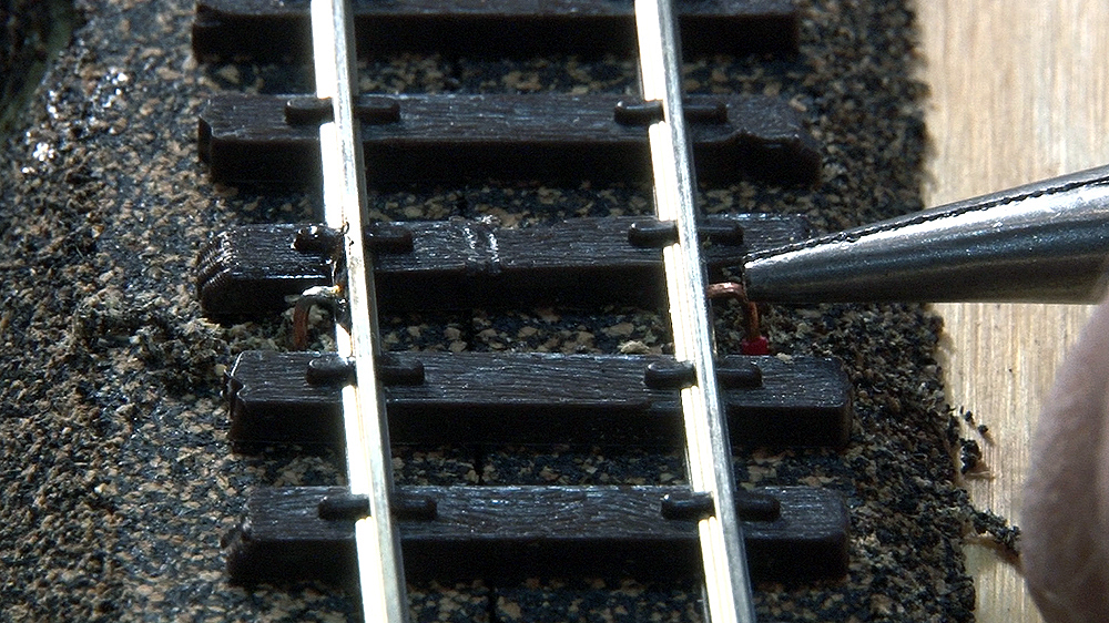
Using the color code from step 1, I insert the appropriate feeder into the hole. If the hole is a bit too tight, it helps to pull the feeder through by grasping it from under the layout. The flat tip of the feeder should come to rest on the top of the foot of the rail. If it does not make good contact, pull the feeder up a bit and make small adjustments to it using a pair of needle-nosed pliers.
Step 6 – Apply flux
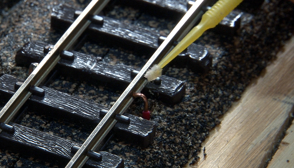
With the feeder properly positioned, I apply a small amount of rosin flux to the joint with a microbrush. Rosin flux is used for electrical work, and it allows the solder to flow into the joint easily. A little flux goes a long way. You can find rosin flux at most stores that sell soldering supplies. Do not use the acid flux that is used in plumbing. This type of flux is corrosive and should never be used with electronics.
Step 7 – Heat and solder
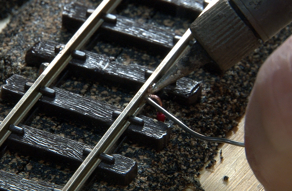
Next, I apply heat to the end of the wire and the rail using a 30-Watt soldering iron with a pencil tip. I like the pencil tip (as opposed to the wider chisel tip) as it allows me to put the heat and solder right where I want it. Avoid using too much solder. You need just enough to hold the wire to the foot of the rail.
Step 8 – Check your work
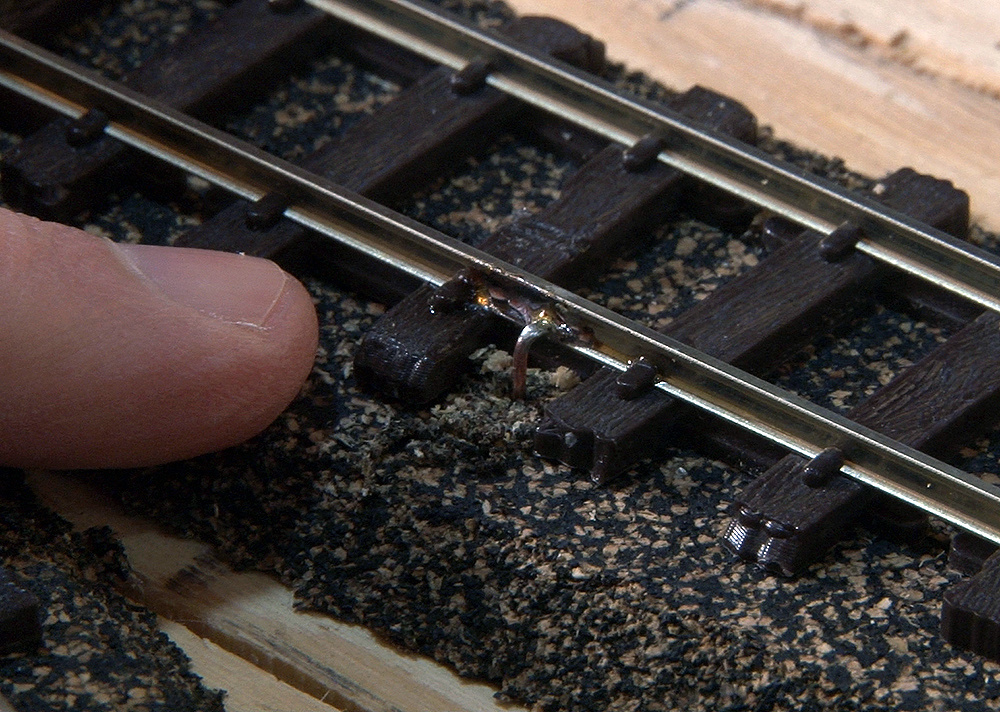
A good solder joint will be shiny when it cools. If the joint looks dull, reheat the solder and let it cool again. A dull joint is a sign that the part moved during the cooling process, and it is not secure. When the wire has cooled, give it a tug from under the layout to make sure it holds.
Step 9 – Clean up
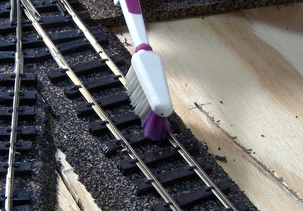
As shown in the previous step, there can be some rosin residue left after the soldering process. Clean this off the rail and the wire with denatured alcohol and an old toothbrush. If rosin is left on the rail, it will keep paint from adhering to that spot. It can also get on the wheels of your trains and be spread all over the layout where it will attract dirt and dust.
Step 10 – Connect to bus
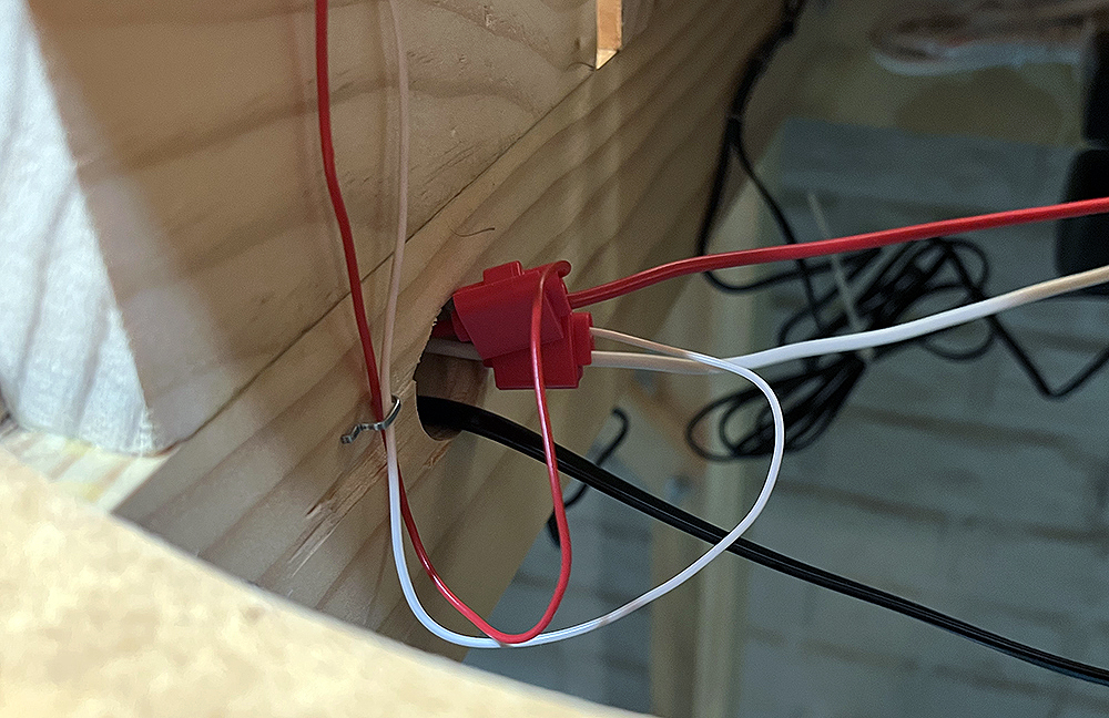
After the feeder wires are attached to the rail, connect them to your power bus under the layout and you’re ready to run trains. It doesn’t take long to learn this technique, and once you’ve had a bit of practice, you should be able to install and solder a pair of feeders in under 5 minutes.


While waiting for professional response:
Attaching wire to rail joiners may sound as a good plan, as one can freely use flux and more easily clean the joint and — like You said — there is no danger of melting the ties with excessive heating.
But:
Rail joiners may be of a metal that is not easily soldered (steel?). The excessive heat may affect the springing qualities of the joiner and make contact between rail and joiner less solid. As model railroads are in general ballasted, the ballast cement (PVA glue, Matte Medium etc) may find its way between joiner and rail, espcially as the surface tension of the glue/medium has been reduced with dish washing liquid, PhotoFlow etc, so an insulating film may be created between rail joiner and rail. As humidty changes cause shrinkage and expansion of the wooden model railroad baseboards the rails will move slightly back and forth during the year and this will shift dirt between the metal contact of the rail and joiner.
I would avoid unnessecary deforming the feeder/dropper wire by squeezing and then bending the hard copper wire, as it may even snap due to this heavy deformation.
I would make two consecutive bends to feeder/dropper wire so that the first bend would bend the wire from vertical to horisontal in the direction of sleepers (like you have done), but I would then bend the tip with another 90 degree bend so that the wire end would become in direction of the rail. This way one could solder the wire more solidly at the joint of rail profiles’s web and foot.
Instead of using any sort of flux I would suggest first using a fibre glass burnishing tool to clean the rail and pre-solder the rail and wire separately and, after having both pre-tinned, it would be easy to join two pre-tinned parts together by keeping the wire aginst the rail profile and have no need for yet another hand for the solder.
Soldering the wire on the side of the rail is considered old fashioned these days. More professional way would be to solder the wire below the foot of the rail. Same burnishing and pre-tinning applies. This needs more thinking in advance as the position needs to be marked beforehand or the hole through the baseboard be drilled afterwards according to loation the rail and sodered joint sets after bending and fastening the track in final position.
It is indeed a good plan to have the bus wires drawn through same hole to keep the wires close together and hopefully slightly twisted like you have done to avoid causing any electrical noise problems. Using suitcase connectors is a good plan. Suitcase connectors with “spade” tap allows disconnecting the feeder/dropper wire from the bus for fault finding. If the feeder/dropper wire is soldered to bus wire, the joints should be slightly staggered to avoid having shorts in case the insulation tape peels off from both joints in the future.
Similar ideas at: https://www.nmra.org/beginners-guide-part-5-adding-power
A smart company would manufacture short sections of track with the feeder wires already pre-attached, preferably on the underside.
Good technique, David. Thank you so much for sharing it. But I’ve always wondered… why solder the wires to the rails when you can solder them to the joiners? I see at least two advantages in it: a) the wires and the soldering can be hidden better (since you can solder the wires to the bottom of the joiners); and b) absolutely no risk of damaging sleepers and other plastic elements. It would work for you?
IMO, and from experience, soldering the drops to the rail joiners means you have multiple “activities” occurring at the same time and in the same location:
1) soldering the drops to the rail joiner,
2) soldering the rail joiner to the rails.
I have found it is almost impossible to keep everything together while soldering three different parts together at the same time. Besides, often times, I have found that the location for the drops rarely conveniently occurs at the same location as my rail joiners.
Again, IMO ….. 👍