


The following project is an update of Gary D. Patterson’s “Simplified CTC signals” in the July 1988 issue of MR. Bringing the project up to date was a large endeavour. The block control project now incorporates “all” solid-state components controlled by an Arduino microcontroller. I refer to this updated article as “CTC Signals 2.0.”
The scope of the project included many disciplines, such as electronic components selections, circuitry, building light-emitting diode (LED) signals, building the printed-circuit board (PCB), and programming the controller. I’ve broken it down into four major parts, as follows. In each section, numerous diagrams and pictures are included to help with the explanation.
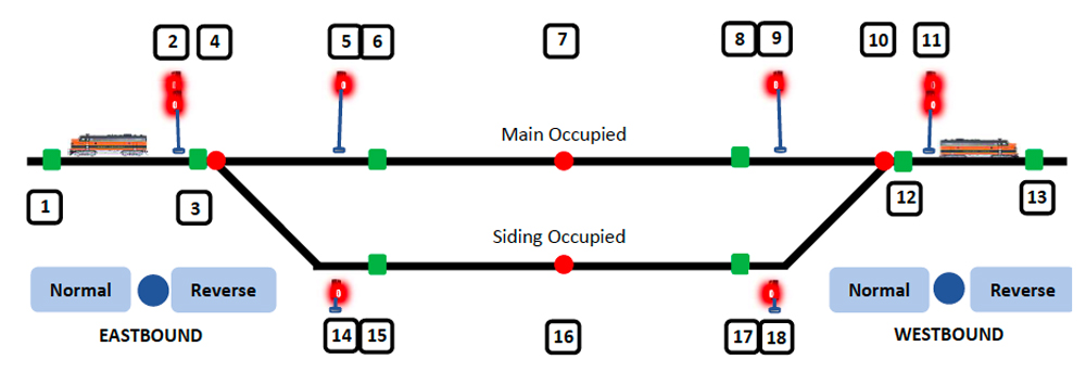
Part 1 — Basic concepts, terminology, and overall block logic
The 1988 story referenced above presented a design that allowed the dispatcher to change the signal lights depending on which routes the trains take through a passing siding. The signal lights were controlled by the turnouts, which were manually controlled by the dispatcher.
The reason for this update is to increase the level of automation, but not to the point of eliminating the role of dispatcher. The controller is set to automatically position the departure turnout based on the trains position and considers whether there is any opposing traffic. The Arduino microcontroller also controls the signals to match the turnouts. The system is set as a self-contained block with two entry points which I call “EB Approach” and “WB Approach.” Both points correspond to sensors in the track and either will initiate the logic block. The only thing that the dispatcher must do is assign the first train to a route and then set the entry turnout accordingly. The controller will do the rest until the block is clear, with the exception being a train “on hold” in the siding. A train can be held for scheduling purposes or if the dispatcher is aware of any higher priority train approaching in either direction.
Terminology
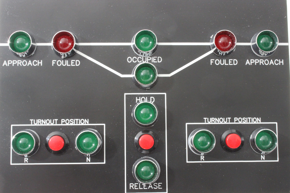
Before we dive into the logic of how the controller processes trains through the block, we need to define the types and locations of the sensors and other critical components.
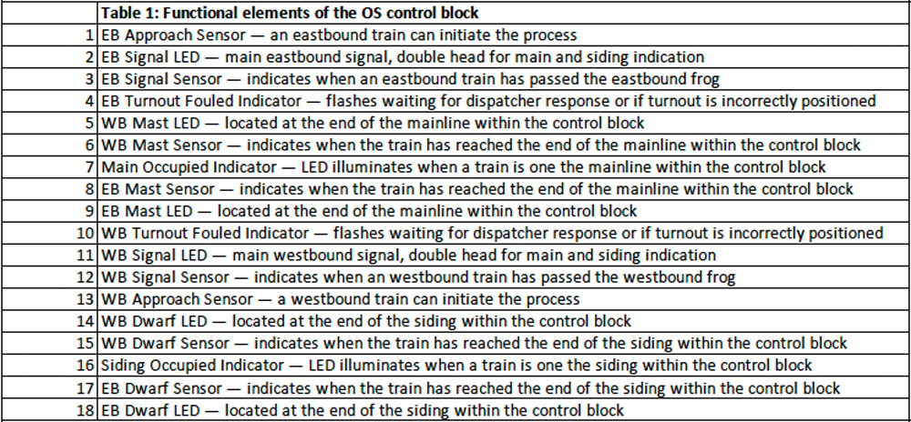
The following illustrations explain the logic for a typical meet at this passing siding.
To explain the logic, let’s assume that the eastbound train is the first to the control block and it will proceed onto the main because it has a higher priority than the approaching westbound.
Table 2: Track indications
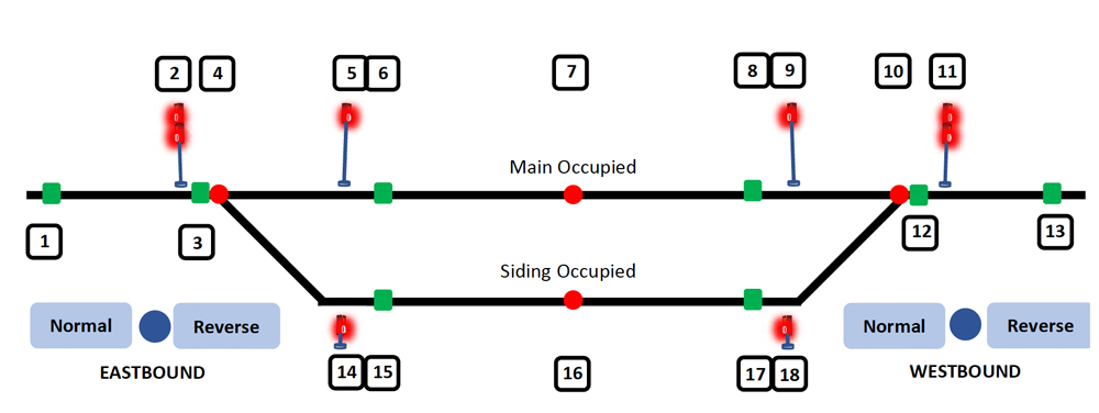
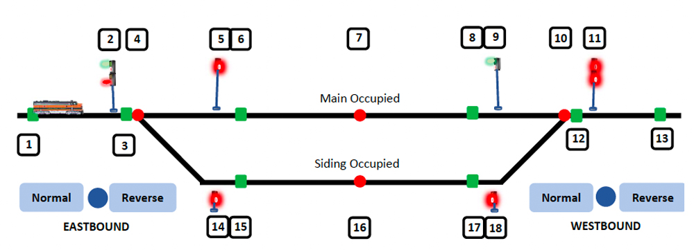
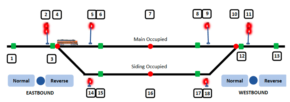
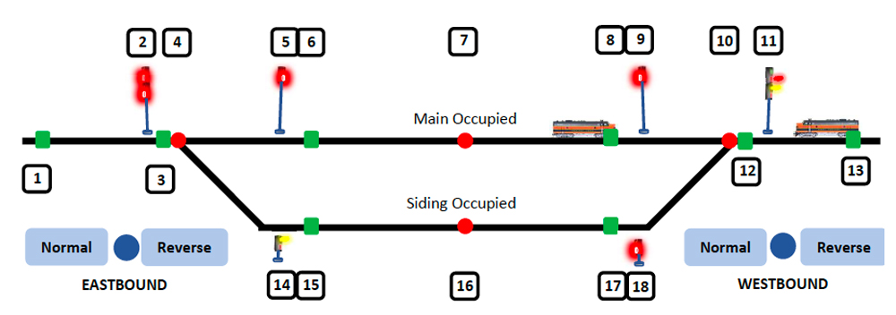
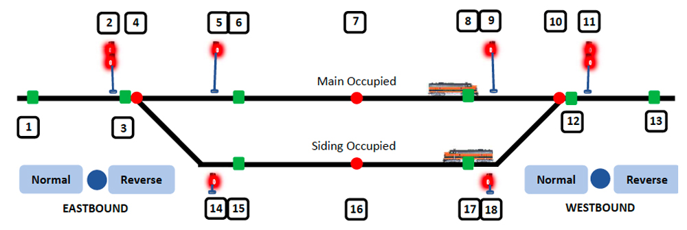
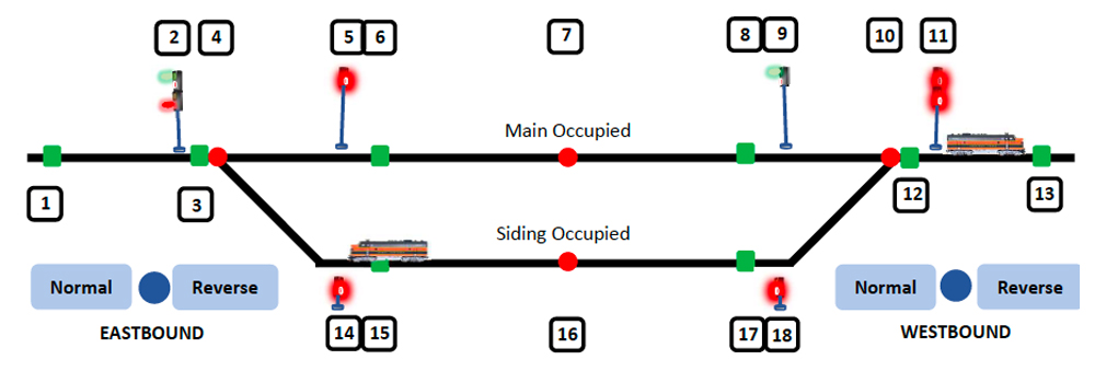
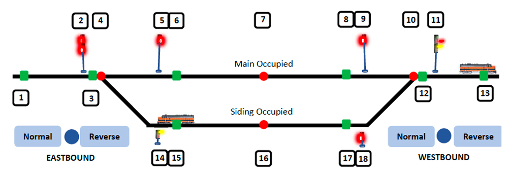
The “hold” button is used to keep a train on the siding for train-schedule purposes. If it’s truly a passing meet, the train on the siding is automatically cleared.
This controller is a stand-alone product that doesn’t require any interconnection with other control blocks. It’s recommended to locate the approach sensors as far as possible from the control block to provide sufficient time for setting the turnout position.
Part 2 — Components and prototype
In this section, we’ll look at the technology options for each of the components and consider the benefits of each. Keep in mind that the goal is to be 100% solid-state with proven, simple, and reliable products.
Sensors
I wanted to find an option that would be foolproof in its ability to pinpoint the location of trains within the control block. The reed switches used in the original article are effective, but I wanted to eliminate the need for making conversions on the locomotives to accommodate the magnets, while at the same time, eliminating the inefficiencies of mechanical devices.
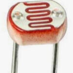
Photocells are often referred to as photoresistors. Common types contain cadmium sulphide, a light-sensitive compound. In the dark, they exhibit an exceedingly high resistance, up to several megohms. Their resistance drops when light shines on the surface. Because the resistance varies with the amount of light, they’re considered analog components.
Photocells are passive devices that are most frequently used in a voltage divider configuration, as shown here. The voltage that’s read at the signal point is a function of the amount of light which controls the resistance of the photocell. As such, they don’t have a sharp on/off signal, typical of photodiodes or phototransistors, which are true semiconductor devices.
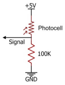
I’ve seen numerous references to IR sensors, usually with an IR beam directed across the track. The receiver is positioned to detect a reflected beam when a train passes. These may have been a good option, but were discounted for several reasons:
- IR sensors must be mounted above grade and have two components that would need to be scenicked.
- The two components increase the wiring needed. One set of wires is required to turn on the LED, and a second set of wires is needed to connect the receiver.
- These sensors need to be carefully aligned for accurate detection.
Since none of the above met the needs, the choice became phototransistors.
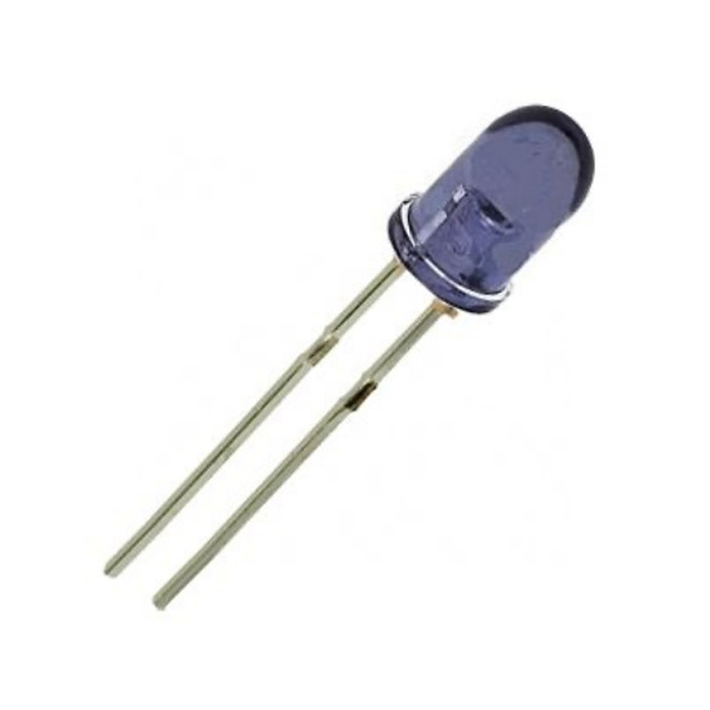
Phototransistors belong to the family of transistors. Transistors function as switches, they’re either on or off, making them true digital components.
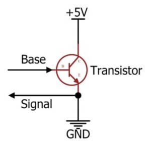
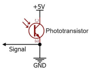
These diagrams compare the activation of transistors and phototransistors. A transistor requires a voltage to be applied on the base to turn on the transistor. When it’s on, current can flow from the power source to ground. Phototransistors don’t have a base connection. They’re activated when light shines on them, which turns them on or off.
Phototransistors would be the sensor of choice, but where is the optimum place to locate them on the layout?
For the overall layout, the dispatcher needs to think in terms of block limits. The approach sensors need to be located as far from the turnouts as possible thus defining the block limits. Additionally, this would give the dispatcher the maximum time to set the turnout correctly to initiate the program. However, there can’t be any other access points onto the main between the Approach sensor and the Signal sensor (points 1 & 3 in the terminology).
The Signal sensor should be placed at the frog to indicate entry into the block. Because this sensor can be used to indicate that the train has entered the appropriate track, there shouldn’t be a long time-delay for the train to clear the frog.
The Mast sensor is placed at the end of the mainline section before reaching the block departure turnout. It needs to be in front of the signal so that the red signal can be activated and seen by the engineer.
The Dwarf sensor is placed at the end of the siding section before reaching the departure turnout, for the same reason as discussed above.
Entry into the block is indicated by a “true” signal at the Mast sensor (or Dwarf) or by a “false” response at the Signal sensor.
LEDs
The Mast and Dwarf lights mimic the main signal, so wiring them in parallel (diagram below) reduces the number of output pins from the microcontroller.
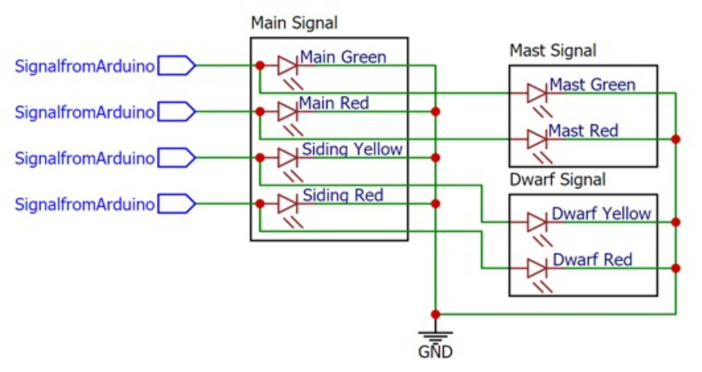
Only the LEDs of the main double-head Signal LED are controlled by the program. The Mast and Dwarf sensors are mimicked by wiring in parallel.
For this project, I made custom LEDs as described in my article in an upcoming issue of MR.
Push buttons
The push buttons selected for turnout position control and for hold/release are the momentary press type. These are an update compared to the older double-pole double throw (DPDT) switches. The program contains code that interprets the pressing action and latches the position setting until it is pressed again.
Optocouplers
As I wrote in my previous story about touch screen control (which can be found in the October 2022 issue of MR), I use optoisolators (or optocoupler) to control the operation of the Tortoise by Circuitron machines. An optoisolator is like a relay in that a signal causes a switch to open.
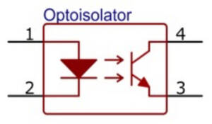
An optoisolator has two components in the IC body: pins 1 and 2 represent the control side, which is an embedded IR LED. The output side is a phototransistor which is activated by the light from the LED. When a 5V supply is connected to pin 1, the photodiode starts to emit light which is aimed at the phototransistor. This causes current to flow from pin 4 to pin 3. The key feature is that there’s no electrical connection. In my project, all power is at a 5VDC level except the Tortoise by Circuitron machines which are at 12V. A voltage level of 12V would destroy the board, so electrical isolation is important.
Microcontroller
Today’s microcontrollers are power-packed when you consider the current prices. For under $10 (for a clone, genuine products are about $30), a user gets an 8-bit, 16MHz, 32kB RAM mini-computer. While not super-fast, the requirements for a model railroad do not fall into the category of microsecond time sensitive.
The workhorse in the hobby industry is the Arduino microcontroller. There a three main types: Uno, Nano and Mega. They all work with the same processor, but the memory and number of input/output (IO) changes. The footprint also changes. The differences are:
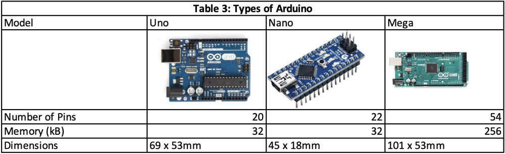
These boards are referred to as development boards. For convenience, all the pins are traced out to the headers for easier development of prototypes. In addition, the development boards also contain power distribution, programmer chips, oscillator, communication interfaces, and LED indicators. More advanced users can use the bare microchip to save space on their printed circuit boards.
Genuine Arduino boards can get pricey, but they are open-sourced and have been cloned by many suppliers. The clones work equally well and save a lot of money.
A prime consideration in the selection of a microcontroller is the number of input/output (I/O) pins that are required for a project. As a project develops, it isn’t uncommon to run out of pins.
The best way to maximize the functionality of an Arduino is to use peripheral devices such as pin extenders, shift registers, and multiplexers to increase the number of available pins, and to optimize the programming.
The program, which we’ll go into detail later, is less than 10kB, which means that a single Nano could control up to 3 blocks. The Mega could process 24 blocks.
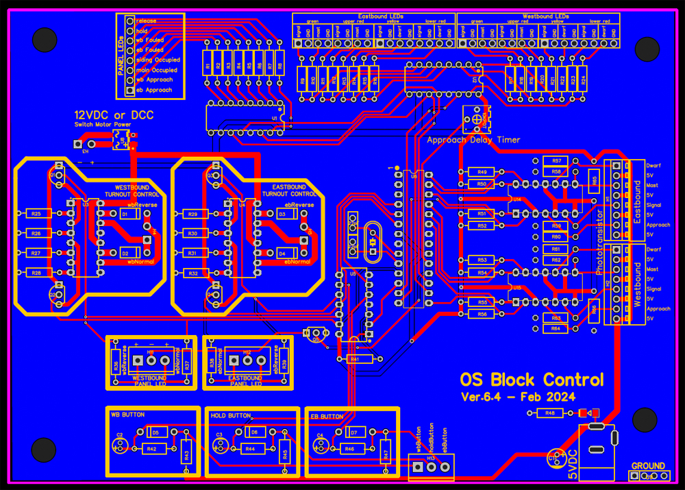
Part 3 — PCB build
The goal I had in mind was to create a system suitable to build a dispatcher’s board from.
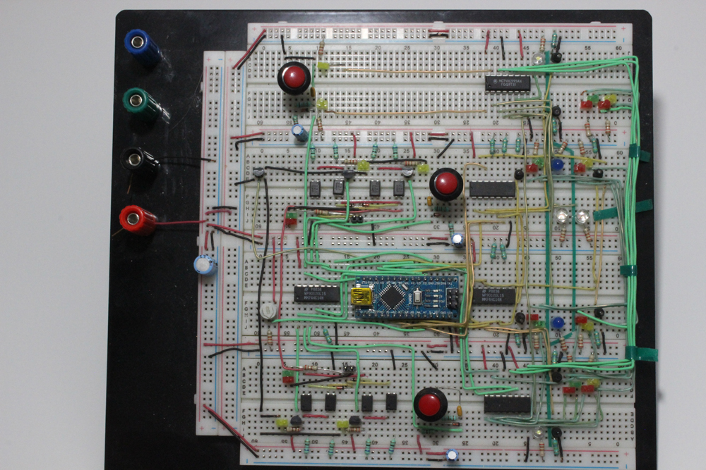
As the schematic is developed, it’s advisable to create the circuit on a breadboard where it can be tested for function. A breadboard enables connecting various components to see if they do what’s intended. The figure below shows the prototype for this controller. Every component on the breadboard is transferred onto the PCB.
Part 4 — Arduino program
Arduino provides on its website a free download of their Integrated Development Environment (IDE) which is essentially an app that facilitates the programming.
This IDE uses the C++ program language. When the program is complete, the IDE compiles it to check for errors. If there are none, it’s ready to upload to the Arduino.
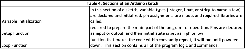
There are three major components of an Arduino sketch: the initialization of variables, the setup loop, and the main loop program. When executed, the sketch will run continually until it is powered down.
The Loop for this project has three main elements to control the block: Turnout position, LED signals, and push-button controls. The following table shows the handler routine for a train approaching at the EB sensor and contains all the logic given in Table 2. The information after the double slashes (//) are comments for clarity.
The code is activated, in this case, by the EB Approach sensor. A decision is made by the dispatcher whether this train will stay on the main or divert to the siding. Then, the EB ENTRY HANDLER ROUTINE is executed. Once the EB is in the block, a check is run to see if a WB has arrived. If so, it will be assigned to the other route by running the WB ENTRY HANDLER ROUTINE. Since priority is given to the main, the CLEAR MAIN routine is run next. Finally, the CLEAR SIDING routine clears the siding.
Table 5: Program snippet for the EB HANDLER ROUTE
There’s a similar block of code for the WB Approach.
As covered earlier, effective allocation of pins is a major consideration. There are too many LEDs to assign a pin to each signal. This is overcome using shift registers. These devices are serial to parallel converters in which data is supplied serially to the chip which converts it into parallel data. In this way, one data line controls eight LEDs.
Table 6: Signal LED output program snippet
Below is the code to release a train that was previously held on the siding.
Table 7: Program snippet to release hold train
If there are no trains near the block, the program constantly repeats the LOOP function. It’s waiting for a trigger to begin full execution. For us, the trigger is the detection of a train at either the EB or WB Approach sensor.
Imagine when there’s no road traffic: The program just blindly loops. However, it needs to know when something has happened, such as a train tripping one of the approach sensors. Execution of the code needs to begin instantly, but what happens if the code is in another part of the loop running other commands where it’s not watching the sensors.
This is what interrupt routines do. They wait for an extraordinary event which will disrupt the normal program flow so that the interrupt routine can be processed. In this case, the program would jump to the interrupt routine and process the approach, and from there jump back into the main program to execute the approach handler.
Table 8: Approach sensor detection function
These interrupts need to confirm whether an input at an approach sensor is truly a train coming into the block or if it a train leaving. There is an internal flag to indicate a train that is leaving the block.
A complete listing of the Arduino sketch is given in the Appendix.
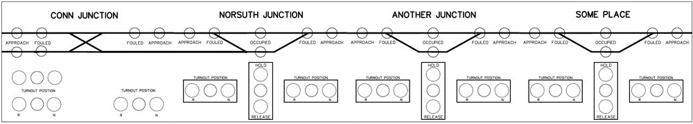
Hot off the press
This article was written with the intent of the PCB acting as the control panel. It’s possible to add Wi-Fi functionality to an Arduino and use the Arduino to generate a webpage that can be viewed on a monitor. The push-button controls can be activated by mouse-clicking or pressing on a touchscreen.
The following is a sample page representing the Norsuth Junction via a webpage on a local internet connection.
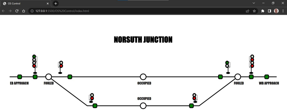
This is further evidence of where technology can advance the enjoyment of the hobby.
My hope is that this story has invoked a sense of curiosity among the readers to the point they can see the potential applications for microcontrollers in model railroading. Personally, I have about 20 more projects using Arduino on my to-do list. More to come later.
The following is a complete listing of the code I have used.
Appendix: Arduino sketch
001 #include <Arduino.h>
002 #include <avr/sleep.h>
003
004 /*LED OUTPUT VARIABLES
005 ledSignals1 bits || 7=ebGreen, 6=ebRedMain, 5=ebYellow, 4=ebRedSiding, 3=wbGreen, 2=wbRedMain, 1=wbYellow, 0=wbRedSiding
006 ledSignals2 bits || 7=ebApproach, 6=wbAllroach, 5=mainOccupied, 4=sidingOccupied, 3=ebFouled, 2=wbFouled, 1=hold, 0=release
007 */
008 volatile byte ledSignals1 = 0b00000000;
009 volatile byte ledSignals2 = 0b00000000;
010
011 byte oldSignals2;
012
013 int delayTime = 3000;
014
015 int isHoldingPin = 2;
016 int switchWBposition = 3;
017 int switchWBpositionPin = 4;
018 int switchEBposition = 5;
019 int switchEBpositionPin = 6;
020 int dataPin = 7;
021 int ebSwitchApproachPin = 8;
022 int wbSwitchApproachPin = 9;
023 int latchPin = 10;
024 int clockPin = 11;
025 int killPin = 12;
026 int wbSwitchSignalPin = 14;
027 int wbSwitchMastPin = 15;
028 int wbSwitchDwarfPin = 16;
029 int ebSwitchSignalPin = 17;
030 int ebSwitchMastPin = 18;
031 int ebSwitchDwarfPin = 19;
032 int timerPin = A6; //analog A6
033
034 volatile int ebSwitchPosition;
035 volatile int wbSwitchPosition;
036 volatile int holdState = 1;
037 int trackOption;
038 volatile int hasStarted = 0;
039 int holdDirection = 0; //1 = EB | 2 = WB
040 volatile int ebSwitchApproach = 0;
041 volatile int wbSwitchApproach = 0;
042 volatile int ebSwitchSignal;
043 volatile int ebSwitchMast;
044 volatile int ebSwitchDwarf;
045 volatile int wbSwitchSignal;
046 volatile int wbSwitchMast;
047 volatile int wbSwitchDwarf;
048
049 int ebPosition;
050 int wbPosition;
051 unsigned long counter;
052 volatile int ebDeparted = 0;
053 volatile int wbDeparted = 0;
054 volatile int ebApproachSwitched = 0;
055 volatile int wbApproachSwitched = 0;
056 volatile int holdSwitched = 0;
057 volatile unsigned long i;
058
059 unsigned long startSleepTime;
060 volatile int isAsleep = 0;
061 int timerScale;
062
063 void setup() {
064 Serial.begin(115200);
065
066 pinMode (isHoldingPin, INPUT);
067 pinMode (switchEBposition, OUTPUT);
068 pinMode (switchEBpositionPin, INPUT);
069 pinMode (dataPin, OUTPUT);
070 pinMode (latchPin, OUTPUT);
071 pinMode (ebSwitchApproachPin, INPUT);
072 pinMode (wbSwitchApproachPin, INPUT);
073 pinMode (switchWBpositionPin, INPUT);
074 pinMode (switchWBposition, OUTPUT);
075 pinMode (clockPin, OUTPUT);
076 pinMode (ebSwitchSignalPin, INPUT);
077 pinMode (ebSwitchMastPin, INPUT);
078 pinMode (ebSwitchDwarfPin, INPUT);
079 pinMode (wbSwitchSignalPin, INPUT);
080 pinMode (wbSwitchMastPin, INPUT);
081 pinMode (wbSwitchDwarfPin, INPUT);
082 pinMode (killPin, OUTPUT);
083 pinMode (timerPin, INPUT);
084 /*
085 killPin feeds base of transistor to provide ground for PCB mounted LED; if LOW, all LED are OFF
086 */
087 digitalWrite (killPin, HIGH);
088
089 /*INTERRUPTS
090 INT0 detects pressing the hold pin, D2; also reconfigured as wakeup if system goes to sleep
091 INT1 not used
092 PCMSK0 calls ISR(PCINT0_vect) for approach triggers
093 094 PCMSK1 calls ISR(PCINT1_vect) for change in signal, mast or dwarf sensors
095 PCMSK2 calls ISR(PCINT2_vect) for change in turnout position
096 */
097 attachInterrupt (digitalPinToInterrupt(isHoldingPin), holdPressed, RISING);
098 PCICR |= 0b00000111;
099 PCMSK0 |= 0b00000011;
100 PCMSK1 |= 0b00111111;
101 PCMSK2 |= 0b01010000;
102 }
103 void loop() {
104 /*
105 Adjustable timer to change the wait time between approach trigger and setting of turnout position
106 This is dispatcher’s reaction time to route the train
107 */
108 timerScale = map(analogRead(timerPin), 0, 1023, 2, 120);
109
110 interrupts();
111 hasStarted = 0;
112
113 //INITIALIZE ALL TRACKSIDE SIGNALS RED
114 ledSignals1 = 0b10101010;
115 outShift();
116
117 /*
118 SYSTEM WILL SLEEP IF THERE HAS BEEN NO MOVEMENT WITHIN DEFINED PERIOD
119 */
120 startSleepTime = millis();
121
122 /*
123 PROGRAM BEGINS EXECUTION WHEN AN APPROACH SENSOR HAS ACTIVATED OR IF THE RELEASE BUTTON IS PRESSED
124 PROGRAM STAYS IN WHILE LOOP UNTIL ACIVATED OR SLEEP TIMER ACTIVATED
125 */
126 while (ebSwitchApproach == 0 && wbSwitchApproach == 0 && hasStarted == 0 && holdState != 3) {
127 if (millis() – startSleepTime >= 30000) {
128 noInterrupts();
129 isAsleep = 1;
130 set_sleep_mode(SLEEP_MODE_PWR_DOWN);
131 PCICR = 0b00000000;
132 digitalWrite(killPin, LOW);
133 ledSignals1 = 0b00000000;
134 oldSignals2 = ledSignals2;
135 ledSignals2 = 0b00000000;
136 outShift();
137 delay(50);
138 sleep_enable();
139 attachInterrupt(digitalPinToInterrupt(isHoldingPin), wakeUp, FALLING);
140 interrupts();
141 delay(1000);
142 sleep_cpu();
143 /*
144 RETURN POINT AFTER WAKEUP
145 */
146 attachInterrupt(digitalPinToInterrupt(isHoldingPin), holdPressed, RISING);
147 digitalWrite(killPin, HIGH);
148 PCICR |= 0b00000111;
149 ledSignals1 = 0b10101010;
150 ledSignals2 = oldSignals2;
151 outShift();
152 startSleepTime = millis();
153 delay(50);
154 }
155 outShift();
156 }
157 //APPROACH LED BLINKS FOR TIME INTERVAL SET BY POTENTIOMETER (APPROX 1-60 SECOND)
158 for (counter = 1; counter <= timerScale; counter++) {
159 if (ebSwitchApproach == 1) {
160 ledSignals2 = ledSignals2 ^ 0b10000000;
161 }
162 else if (wbSwitchApproach == 1) {
163 ledSignals2 = ledSignals2 ^ 0b01000000;
164 }
165 outShift();
166 delay(500);
167 }
168 /*
169 hasStarted = 1 STARTS PROGRAM EXECUTION
170 trackOption = 1 IS EB TRIGGER
171 trackOption = 2 IS WB TRIGGER
172 trackOption = 3 IS EB RELEASE
173 */
174 hasStarted = 1;
175 if (hasStarted == 1) {
176 if (ebSwitchApproach == 1 && holdState != 3) {
177 trackOption = 1;
178 }
179 if (wbSwitchApproach == 1 && holdState != 3) {
180 trackOption = 2;
181 }
182 if (holdState == 3) {
183 trackOption = 3;
184 }
185
186 /*LOGIC BLOCKS TRACK WHERE TRAINS ARE
187 0 = no TRAIN | 1 = TRAIN ON MAIN | 2 = TRAIN ON SIDING
188 */
189 ebPosition = 0;
190 wbPosition = 0;
191
192 switch (trackOption) {
193
194 case 1:
195 /*
196 EB APPROACH TRIGGERED
197 EB ENTRY HANDLER ROUTINE
198 */
199 if (holdState == 2 && ebSwitchPosition == 1){
200 while (ebSwitchPosition == 1){
201 EBfouled();
202 }
203 }
204 if (ebSwitchPosition == 0) { //EB SWITCH SET TO MAIN
205 ebPosition = 1; // EB IS ON MAIN
206 greenRedEBsignal(); //GIVE GREEN TO ENTER MAIN, RESET TO RED WHEN REACH EBMAST
207 }
208 else if (ebSwitchPosition == 1 && holdState == 1) { //CHECKS IF SIDING IS ON HOLD
209 ebPosition = 2; //EB IS ON SIDING
210 holdDirection = 1; //FLAGS THE DIRECTION THE TRAIN WAS GOING WHEN PUT ON HOLD 1=EB 2=WB
211 redYellowEBsignal(); //EB ENTERS THE SIDING, SIGNALS RESET TO RED/RED WHEN REACHES EB DWARF
212 }
213 /*
214 WB ENTRY HANDLER ROUTINE (IF NECESSARY)
215 */
216 if (wbSwitchApproach == 1) { //CHECK FOR WB
217 while (wbSwitchPosition == ebSwitchPosition) { //IF SWITCHES ARE THE SAME, SWITCH IS FOULED
218 WBfouled(); //FUNCTION TO BLINK LED, WAIT FOR SWITCH TO BE CHANGED
219 }
220 if (wbSwitchPosition == 0) { //WB SWITCH SET TO MAIN
221 wbPosition = 1; //WB IS ON MAIN
222 greenRedWBsignal(); //WAITS FOR WBMAST TO INDICATE TRAIN IS IN, THEN SETS RED/RED
223 }
224 else if (wbSwitchPosition == 1 && holdState == 1) { //WB SWITCH SET TO SIDING
225 wbPosition = 2; //WB IS ON SIDING
226 holdDirection = 2; //FLAGS THE DIRECTION THE TRAIN WAS GOING WHEN PUT ON HOLD 1=EB 2=WB
227 redYellowWBsignal(); //WB ENTERS SIDING, SIGNALS SET TO RED/RED WHEN REACHES WBDWARF
228 }
229 }
230 /*
231 CLEAR MAIN HANDLER ROUTINE
232 */
233 if (ebPosition == 1) { //CLEAR EB ON MAIN
234 while (wbSwitchPosition == 1) { //CHANGE WB SWITCH POSITION TO MAIN
235 WBfouled();
236 }
237 ebDeparted = 1;
238 greenRedEBmast(); //EB CLEARS MAIN, SIGNALS RESET TO RED/RED
239 }
240 if (wbPosition == 1) { //CLEAR WB ON MAIN
241 while (ebSwitchPosition == 1) { //CHANGE EB SWITCH POSITION TO MAIN
242 EBfouled();
243 }
244 wbDeparted = 1;
245 greenRedWBmast(); //WB CLEARS MAIN, SIGNALS RESET TO RED/RED
246 }
247 /*
248 CLEAR SIDING AS LONG AS NO HOLD HANDLER ROUTINE (IF NECESSARY)
249 */
250 if (holdState == 1) { //CLEARS SIDING IF NOT ON HOLD
251 if (ebPosition == 2) { //CLEAR EB ON SIDING
252 while (wbSwitchPosition == 0) { //CHANGE WB SWITCH POSITION TO SIDING
253 WBfouled();
254 }
255 ebDeparted = 1;
256 redYellowEBdwarf(); //EB CLEARS SIDING
257 }
258 else if (wbPosition == 2) { //CLEAR WB ON SIDING
259 while (ebSwitchPosition == 0) { //CHANGE EB SWITCH POSITION TO SIDING
260 EBfouled();
261 }
262 wbDeparted = 1;
263 redYellowWBdwarf(); //WB CLEARS SIDING
264 }
265 }
266 ebSwitchApproach = 0;
267 wbSwitchApproach = 0;
268 ebApproachSwitched = 0;
269 wbApproachSwitched = 0;
270 break;
271
272 case 2:
273 /*
274 WB APPROACH TRIGGERED
275 WB ENTRY HANDLER ROUTINE
276 */
277 if (holdState == 2 && wbSwitchPosition == 1){
278 while (wbSwitchPosition == 1){
279 WBfouled();
280 }
281 }
282 if (wbSwitchPosition == 0) { //WB SWITCH SET TO MAIN
283 wbPosition = 1; //WB IS ON MAIN
284 greenRedWBsignal(); //GIVE GREEN TO ENTER MAIN, RESET TO RED WHEN REACH WBMAST
285 }
286 else if (wbSwitchPosition == 1 && holdState == 1) { //CHECKS IF SIDING IS ON HOLD
287 wbPosition = 2; //WB IS ON SIDING
288 holdDirection = 2; //FLAGS THE DIRECTION THE TRAIN WAS GOING WHEN PUT ON HOLD 1=EB 2=WB
289 redYellowWBsignal(); //WB ENTERS THE SIDING, SIGNALS RESET TO RED/RED WHEN REACHES WBDWARF
290 }
291 /*
292 //EB ENTRY HANDLER ROUTINE (IF NECESSARY)
293 */
294 if (ebSwitchApproach == 1) { //CHECK FOR EB
295 while (ebSwitchPosition == wbSwitchPosition) { //IF SWITCHES ARE THE SAME, SWITCH IS FOULED
296 EBfouled(); //FUNCTION TO BLINK LED, WAIT FOR SWITCH TO BE CHANGED
297 }
298 if (ebSwitchPosition == 0) { //EB SWITCH SET TO MAIN
299 ebPosition = 1; //EB IS ON MAIN
300 greenRedEBsignal(); //WAITS FOR EBMAST TO INDICATE TRAIN IS IN, THEN SETS RED/RED
301 }
302 else if (ebSwitchPosition == 1) { //EB SWITCH SET TO SIDING
303 ebPosition = 2; //EB IS ON SIDING
304 holdDirection = 1; //FLAGS THE DIRECTION THE TRAIN WAS GOING WHEN PUT ON HOLD 1=EB 2=WB
305 redYellowEBsignal(); //EB ENTERS THE SIDING, SIGNALS RESET TO RED/RED WHEN REACHES EBDWARF
306 }
307 }
308 /*
309 //CLEAR MAIN HANDLER ROUTINE
310 */
311 if (wbPosition == 1) { //CLEAR WB ON MAIN
312 while (ebSwitchPosition == 1) { //CHANGE EB SWITCH POSITION TO MAIN
313 EBfouled();
314 }
315 wbDeparted = 1;
316 greenRedWBmast(); //WB CLEARS MAIN, SIGNALS RESET TO RED/RED
317 }
318 else if (ebPosition == 1) { //CLEAR EB ON MAIN
319 while (wbSwitchPosition == 1) { //CHANGE WB POSITION TO MAIN
320 WBfouled();
321 }
322 ebDeparted = 1;
323 greenRedEBmast(); //EB CLEARS MAIN, SIGNALS RESET TO RED/RED
324 }
325 /*
326 //CLEAR SIDING AS LONG AS NO HOLD
327 */
328 if (holdState == 1) { //CLEARS SIDING IF NOT ON HOLD
329 if (wbPosition == 2) { //CLEAR WB ON SIDING
330 while (ebSwitchPosition == 0) { //CHANGE EB SWITCH POSITION TO SIDING
331 EBfouled();
332 }
333 wbDeparted = 1;
334 redYellowWBdwarf(); //WB CLEARS SIDING
335 }
336 else if (ebPosition == 2) { //CLEAR EB ON SIDING
337 while (wbSwitchPosition == 0) { //CHANGE WB SWITCH POSITION TO SIDING
338 WBfouled();
339 }
340 ebDeparted = 1;
341 redYellowEBdwarf(); //EB CLEARS SIDING
342 } //SIDING IS CLEARED
343 }
344 ebSwitchApproach = 0;
345 wbSwitchApproach = 0;
350 ebApproachSwitched = 0;
351 wbApproachSwitched = 0;
352 break;
353
354 case 3: //RELEASE HOLD TRAIN
355 bitWrite(ledSignals2, 0, HIGH); //RELEASE LED
356 outShift();
357 if (bitRead(ledSignals2, 4 == 1)) { //SIDING IS OCCUPIED
358 if (holdDirection == 1) { //EB ON HOLD
359 if (wbSwitchApproach == 0) { //NO WB TRAIN APPROACHING
360 while (wbSwitchPosition == 0) {
361 WBfouled(); //SETS FOULED INDICATOR ON WB SWITCH
362 }
363 redYellowEB(); //EB PROCEEDS THROUGH WB SWITCH
364 delay(delayTime / 4);
365 while (wbSwitchSignal == 0) {
366 delayMicroseconds(1); //EB CLEARS SIDING
367 }
368 ebDeparted = 1;
369 ledSignals1 = 0b10101010; //EB SIGNALS SET TO RED/RED
370 }
371 }
372 if (holdDirection == 2) { //WB ON HOLD
373 if (ebSwitchApproach == 0) { //NO EB TRAIN APPROACHING
374 while (ebSwitchPosition == 0) {
375 EBfouled(); //SETS FOULED INDICATOR ON EB SWITCH
376 }
377 redYellowWB(); //WB PROCEEDS THROUGH EB SWITCH
378 delay(delayTime / 4);
379 while (ebSwitchSignal == 0) {
380 delayMicroseconds(1); //WB CLEARS SIDING
381 }
382 wbDeparted = 1;
383 ledSignals1 = 0b10101010; //WB SIGNALS SET TO RED/RED
384 }
385 }
386 bitWrite(ledSignals2, 4, !bitRead(ledSignals2, 4)); //RESET SIDING OCCUPIED LED
387 bitWrite(ledSignals2, 0, HIGH);
388 outShift();
389 }
390 holdState = 1; //RESET HOLDSTATE TO NORMAL
391 bitWrite(ledSignals2, 0, LOW);
392 outShift();
393 holdDirection = 0; //CLEAR HOLD FLAGS
394 break;
395 } //end switch case
396 } //END OF STARTED LOOP
397 bitWrite(ledSignals2, 7, LOW); //TURN OFF EBSWITCH APPROACH LED
398 bitWrite(ledSignals2, 6, LOW); //TURN OFF WBSWITCH APPROACH LED
399 outShift();
400 } //END OF MAIN LOOP
401
402 void outShift() {
403 digitalWrite(latchPin, LOW);
404 shiftOut(dataPin, clockPin, MSBFIRST, ledSignals2);
405 shiftOut(dataPin, clockPin, LSBFIRST, ledSignals1);
406 digitalWrite(latchPin, HIGH);
407 }
408 void mainOccupied() {
409 ledSignals2 = ledSignals2 ^ 0b00100000;
410 outShift();
411 }
412 void sidingOccupied() {
413 ledSignals2 = ledSignals2 ^ 0b00010000;
414 outShift();
415 }
416 ISR(PCINT2_vect) { //PCINT FOR TURNOUT SWITCH CONTROLS
417 if (digitalRead(switchEBpositionPin) == 1) { //HAS EB SWITCH BUTTON BEEN PRESSED
418 ebSwitchPosition = !ebSwitchPosition; //FLIP THE POSITION WITH !
419 digitalWrite(switchEBposition, ebSwitchPosition); //SENDS NEW VALUE TO THE MOTOR CONTROLS
420 }
421 if (digitalRead(switchWBpositionPin) == 1) { //HAS WB SWITCH BUTTON BEEN PRESSED
422 wbSwitchPosition = !wbSwitchPosition; //FLIP THE POSITION WITH !
423 digitalWrite(switchWBposition, wbSwitchPosition); //SENDS NEW VALUE TO THE MOTOR CONTROLS
424 }
425 digitalWrite (switchEBpositionPin, LOW); //RESET IF SET BY EBFOULED OR WBFOULED
426 digitalWrite (switchWBpositionPin, LOW);
427 outShift();
428 }
429 /*
430 PCINT TO READ INPUT SENSORS EXCEPT APPROACHES
431 VALUES ARE ASSIGNED TO VARIABLES FOR USE IN THE PROGRAM. VARIABLES ARE EFFECTIVELY RESET BY SUCCESSIVE
432 READS.
433 */
434 ISR(PCINT1_vect) { //
435 ebSwitchSignal = !digitalRead(ebSwitchSignalPin);
436 ebSwitchMast = !digitalRead(ebSwitchMastPin);
437 ebSwitchDwarf = !digitalRead(ebSwitchDwarfPin);
438 wbSwitchSignal = !digitalRead(wbSwitchSignalPin);
439 wbSwitchMast = !digitalRead(wbSwitchMastPin);
440 wbSwitchDwarf = !digitalRead(wbSwitchDwarfPin);
441 outShift();
442 }
443 /*
444 PCINT TO READ APPROACH VECTORS
445 APPROACH VECTORS ACTIVATE THE MAIN PROGRAM.
446 */
447 ISR(PCINT0_vect) {
448 if (!digitalRead(ebSwitchApproachPin)) { //EB BUTTON PRESSED
449 if (ebApproachSwitched == 0 && wbDeparted == 0) { //CHECKS IF SENSOR IS FOR A TRAIN ENTERING OR LEAVING 0 = ENTERING
450 ebSwitchApproach = 1; //VALUE ASSIGNED TO VARIABLE FOR USE IN PROGRAM
451 ebApproachSwitched = 1; //SETS TO 1 TO SKIP SECOND PASS
452 bitWrite(ledSignals2, 7, HIGH); //ACTIVATE BLOCK ON TURN ON APPROACH LED
453 }
454 if (wbDeparted == 1) { //WBDEPARTED SET TO 1 WHEN AN EB CLEARS THE BLOCK
455 ebSwitchApproach = 0; //CLEAR
456 wbDeparted = 0; //RESET BUT DO NOT INITIALIZE PROGRAM
457 bitWrite(ledSignals2, 7, LOW); //LED OFF
458 }
459 }
460 if (!digitalRead(wbSwitchApproachPin)) { //WB BUTTON PRESSED
461 if (wbApproachSwitched == 0 && ebDeparted == 0) { //CHECKS IF SENSOR IS FOR A TRAIN ENTERING OR LEAVING 0 = ENTERING
462 wbSwitchApproach = 1; //VALUE ASSIGNED TO VARIABLE FOR USE IN PROGRAM
463 wbApproachSwitched = 1; //SETS TO 1 TO SKIP SECOND PASS
464 bitWrite(ledSignals2, 6, HIGH); //ACTIVATE BLOCK ON TURN ON APPROACH LED
465 }
466 if (ebDeparted == 1) { //WBDEPARTED SET TO 1 WHEN AN EB CLEARS THE BLOCK
467 wbSwitchApproach = 0; //CLEAR
468 ebDeparted = 0; //RESET BUT DO NOT INITIALIZE PROGRAM
469 bitWrite(ledSignals2, 6, LOW); //LED OFF
470 }
471 }
472 outShift();
473 }
474 /*
475 INTERRUPT 2 REDEFINED IN LOOP TO CATCH WAKEUP
476 */
477 void wakeUp() {
478 if (isAsleep == 1) {
479 sleep_disable();
480 isAsleep = 0;
481 }
482 }
483 /*
484 INTERRUPT 2 HOLD BUTTON PRESSED WHILE AWAKE
485 holdState = 0 – NO TRAIN HELD ON SIDING
486 holdState = 1 – IF PRESSED BEFORE SIGNAL OR DWARF SENSOR, TRAIN WILL BE HELD
487 holdState = 2 – RELEASE TRAIN FROM SIDING WHEN CLEAR, RESET TO 0
488
489 holdState INCREMENTS EACH TIME PRESSED
490 */
491 void holdPressed() {
492 holdSwitched = 0;
493 if (holdSwitched == 0) {
494 holdState = holdState + 1;
495 if (holdState == 1) {
496 bitWrite(ledSignals2, 1, LOW);
497 bitWrite(ledSignals2, 0, LOW);
498 }
499 if (holdState == 2) {
500 bitWrite(ledSignals2, 1, HIGH);
501 bitWrite(ledSignals2, 0, LOW);
502 }
503 if (holdState == 3) {
504 bitWrite(ledSignals2, 1, LOW);
505 bitWrite(ledSignals2, 0, HIGH);
506 }
507 holdSwitched = 1;
508 }
509 outShift();
510 }
511 void greenRedEB() {
512 ledSignals1 = ledSignals1 ^ 0b00000011; //TOGGLES EB RED/GREEN
513 outShift();
514 delay(delayTime);
515 }
516 void greenRedWB() {
517 ledSignals1 = ledSignals1 ^ 0b00110000; //TOGGLES WB RED/GREEN
518 outShift();
519 delay(delayTime);
520 }
521 void redYellowEB() {
522 ledSignals1 = ledSignals1 ^ 0b00001100; //TOGGLES EB RED/YELLOW
523 outShift();
524 delay(delayTime);
525 }
526 void redYellowWB() {
527 ledSignals1 = ledSignals1 ^ 0b11000000; //TOGGLES EB RED/YELLOW
528 outShift();
529 delay(delayTime);
530 }
531 void EBfouled() {
532 ledSignals2 = ledSignals2 ^ 0b00001000; //TOGGLES (ledSignals2, 3);
533 outShift();
534 delay(delayTime / 16);
535 ledSignals2 = ledSignals2 ^ 0b00001000; // FORCES LED TO BE OFF EACH TIME FUNCTION CALLED
536 outShift();
537 delay(delayTime / 16);
538 }
539 void WBfouled() {
540 ledSignals2 = ledSignals2 ^ 0b00000100; //TOGGLES (ledSignals2, 3);
541 outShift();
542 delay(delayTime / 16);
543 ledSignals2 = ledSignals2 ^ 0b00000100; // FORCES LED TO BE OFF EACH TIME FUNCTION CALLED
544 outShift();
545 delay(delayTime / 16);
546 }
547 /*
548 TRACKSIDE LED CONTROLS
549 */
550 void greenRedEBsignal() {
551 greenRedEB();
552 while (ebSwitchSignal == 0 && ebSwitchMast == 0){
553 delayMicroseconds(1);
554 }
555 mainOccupied();
556 greenRedEB();
557 }
558 void greenRedEBmast() {
559 greenRedEB();
560 while (wbSwitchSignal == 0) {
561 delayMicroseconds(1);
562 }
563 mainOccupied();
564 greenRedEB();
565 }
566 void greenRedWBsignal() {
567 greenRedWB();
568 while (wbSwitchSignal == 0 && wbSwitchMast == 0) {
569 delayMicroseconds(1);
570 }
571 mainOccupied();
572 greenRedWB();
573 }
574 void greenRedWBmast() {
575 greenRedWB();
576 while (ebSwitchSignal == 0) {
577 delayMicroseconds(1);
578 }
579 mainOccupied();
580 greenRedWB();
581 }
582 void redYellowEBsignal() {
583 redYellowEB();
584 while (ebSwitchSignal == 0 && ebSwitchDwarf == 0) {
585 delayMicroseconds(1);
586 }
587 sidingOccupied();
588 redYellowEB();
589 }
590 void redYellowEBdwarf() {
591 redYellowEB();
592 while (wbSwitchSignal == 0) {
593 delayMicroseconds(1);
594 }
595 sidingOccupied();
596 redYellowEB();
597 }
598 void redYellowWBsignal() {
599 redYellowWB();
600 while (wbSwitchSignal == 0 && wbSwitchDwarf == 0) {
601 delayMicroseconds(1);
602 }
603 sidingOccupied();
604 redYellowWB();
605 }
606 void redYellowWBdwarf() {
607 redYellowWB();
608 while (ebSwitchSignal == 0) {
609 delayMicroseconds(1);
610 }
611 sidingOccupied();
612 redYellowWB();
613 }


Hello Bryson,
It is fantastic to have an active N scaler on the MR staff. I would like to see more details about this approach to signaling. A pdf file of this article would be very welcome so that it would be easy to reference and print out.
My interest is in creating 4 track position light signal bridges for my N scale layout centered in the Altoona/Horseshoe Curve area. I have purchased parts (bridges, position light heads, and LEDs) from Showcase Miniatures but have not gotten too far with the assembly. One of my roadblocks is how to handle the fragile 5 wires from each signal head without them being hugely over sized. Also finding very small connectors so that the signal bridges are not hardwired into the layout.
In addition to the above, my layout is PRR based BUT I really like the AMTRAK superliners. I have a couple of sets with 3 P42s and the Auto Train autoracks to make a condensed version of the prototype, some amfleets also.
Keep up the good work and get us more N Scale!!
Amby N
So I can take it that there’s no need to look up that 1988 issue of MR about the block signaling – that this update was written to replace that one using the NEW tech we have?
Hi Patrick,
This story stands alone. It’s not connected to any older stories.