


Turnout motors always seemed a bit pricey to me until I learned about servos from a friend who’s a radio control (RC) enthusiast. He uses servos in his aircraft, and they sell for less than $10 each. The “servo” name is a contraction of the term “servomechanism.” These devices use a lightweight can motor to drive a high-ratio gearbox that operates a model aircraft’s flaps and other control surfaces.
This information started my search for servos that eventually led me to the Tower Hobbies website at www.towerhobbies.com. Tower sells the single Hitec model no. HS-311 servo for $7.99 each. If purchased in groups of three for $23.10, the price drops to $7.70 each (special stock number LM3129).
Even if I add a pair of Omron no. 187709 SPDT microswitches (Jameco) to each installation for frog power and signalling, the unit cost remains just slightly over $10 each.
Servo modification
For my use, all I needed was the servo’s DC motor and its matching gearbox. Each servo also includes a printed-circuit (PC) board that’s part of its RC electronics, a three-wire cord, and a plug, which I remove and discard.
I begin modifying the servo by applying a piece of masking tape across the top front of the servo and part way down both sides to secure the faceplate to the case. If you omit this step, removing the four screws from the case allows the entire thing to come apart and you’ll have a handful of little gears.
Next, I flip the servo over so the output shaft faces down and the three wires and plug are at the top. (A Panavise or similar clamping device with nylon jaws is helpful here as a third hand.) I remove the four long screws that hold the servo case together.
Once the case is open, the servo’s motor is at the top with the three-color cable next to it. I carefully remove the PC board and the RC electronic components by unsoldering the board from the motor terminals. Once the board is free, I cut the wires attached to the PC board, and tuck the rest down into the case alongside the motor.
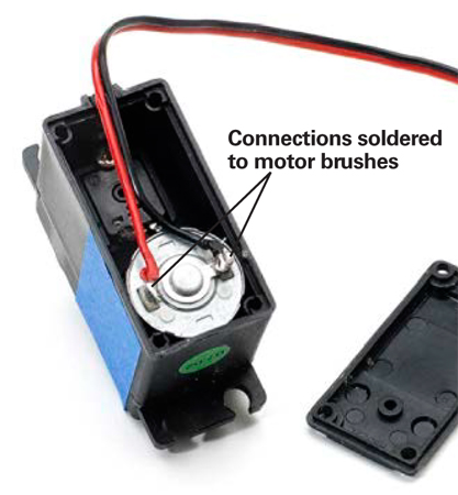
I cut off the connector plug from the wire cable and carefully separate and strip off the yellow wire from the others. I then solder the red wire directly to the right motor terminal, and the black wire to the left terminal as shown in fig. 1. This gives me a DC motor free of electronics with two wires (red and black) coming off the motor terminals. Then I reassemble the case.
Mounting the servo
I center the switch points in their mid-throw position, mark the spot on the layout with an awl, and then drill a ¼” hole through the benchwork. A pair of HO switch points normally moves about 1⁄8″, so the ¼” hole works fine.
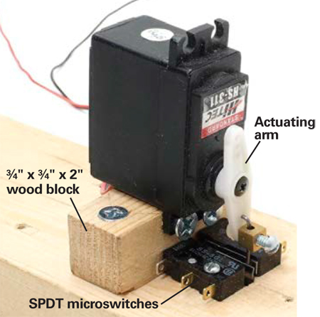
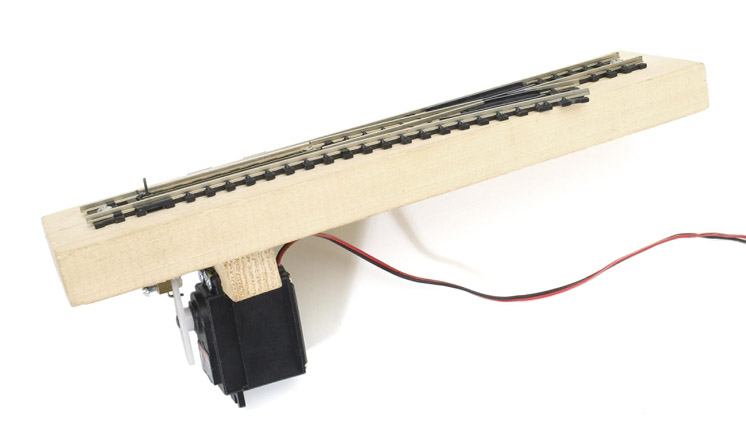
I mount the servo motors under the turnouts on ¾” square blocks of wood, 2″ long, as shown in fig. 2. The servo is centered on the block and secured with a pair of no. 6 x 3⁄8″ panhead screws.
An actuating wire must be added to connect the servo to the turnout’s switch rod. Each servo includes an assortment of plastic arms and wheels that have 1⁄16″ diameter holes for push rods and grooves that match the splines in the servo’s drive shaft. I use a short length of K&S .039″ or .047″ piano wire, bent to fit into the holes in an arm, to convert the servo’s rotary motion into the linear motion that moves the switch points.
Great Planes sells connecting hardware to attach the piano wire to the plastic arms. However, I found the small Allen screws supplied with the connecting rod hardware won’t clamp down on .047″ piano wire. Instead, I use 1⁄2″ 4-40 steel screws that will easily cut threads clear to the bottom of the hole in the brass block so I can tighten them down.
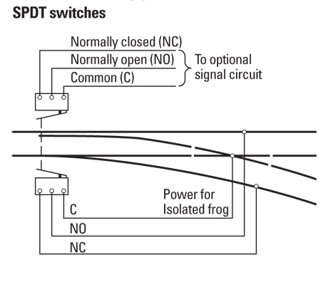
I mount the servo under the switch points so its actuating wire is centered in the ¼” hole and extends up through the switch rod. I also add a microswitch on each side of the actuating wire to power the frog and operate signals. See fig. 2.
Servo operation
Servos will operate on either a single DC power supply or a bipolar supply delivering +12VDC and -12VDC. The bipolar supply allows you to use single-pole double-throw (SPDT) toggles to simplify the turnout control wiring.
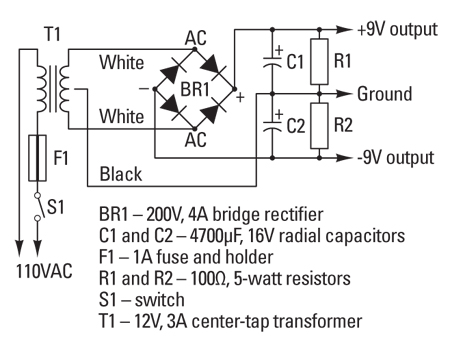
I use a 12V center-tap transformer to produce positive and negative 9V, as shown in fig. 3. Each motor draws 80mA of current, so under an 80 percent load factor, a 3A transformer should handle 25 to 30 motorized turnouts.
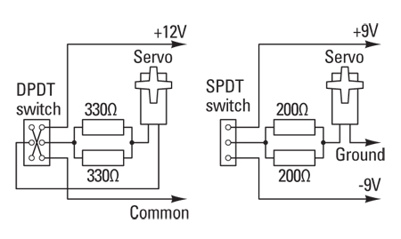
Servos in RC models normally operate on 4.5V to 6V battery packs, so I had to include dropping resistors in the control circuit to reduce the voltage to run the motors. For a 12V power supply, use two 330Ω ½-watt resistors in parallel; for 9V use 200Ω resistors. The wiring diagrams in fig. 4 show both 9V and 12V versions of the control circuits.
Avoiding point drift
The servo gearboxes resist turning by hand, but that’s a bad practice anyway. The gears seem stiff enough, and may hold the switch points in position without a constant application of power.
However, I’ve found that unpowered motors tend to drift open under gentle pressure. The microswitches I use for additional contacts may also cause some drifting because their internal springs have enough pressure to gradually move the points.
To avoid this problem, I use regular toggle switches to control the turnouts so I can maintain constant power to the servos. In this stall mode, each servo motor draws about 66mA of current.
Overall, these servo motors are easy to modify and install. And considering the minimal motion they need to make, the servos’ life expectancy on a model railroad is practically unlimited.
Sources
All Electronics Corp.
(Resistors, toggle switches)
www.allelectronics.com
800-826-5432
Jameco Electronics
(Microswitches, toggle switches)
www.jameco.com
800-831-4242
Tower Hobbies Inc.
(Servos, Great Planes hardware)
www.towerhobbies.com
800-637-4989 (orders only)
800-637-6050 (order assistance


Hmmmm, “building my own electronic” stuff. Not so much. There are 2 solutions from my perspective. First, Tam Valley makes a board which can be used to control a standard servo (micro or whatever you’d like), with either DC or DCC (or both). Second, if you want to do the research, you can use an Arduino as well.
Finally if you source the servos from Asia, via Amazon you can drop the price to C$1.00 a Servo. As well, all the Arduino parts can be sourced MUCH less expensively. You may have to wait a month for shipment but it is way less expensive.
I started by getting the complete Tam Valley solution. Then I switched to getting the parts I needed and doing assembly myself. I’m now at the stage (when I have more time) where I plan to use an Arduino to control multiple servos. I want to use it in a staging yard where I press one button and have 3 turnouts move. That way, I can pick the track number I want with a button and the Arduino will be programmed to move the appropriate turnouts.
I’ve been using the Tam Valley solution for a few months now (in the non-stall setup) and I haven’t had any issues (I build my own turnouts, don’t know if that makes a difference). The gears in the servo naturally resist any movement.
From my RC background, there is one more thing that could be tried. If the servo is moved to a position where there is a small but limited pressure against it, it will hold that and it will not be at stall current. I don’t know what amperage it pulls at that point but it is something to think about. If you use an Arduino, you can set the “throw” of the servo and should be able to accomplish this.
Or, instead of deconstructing the servos, use them as they are meant to be used and take advantage of the built in feedback mechanism that gives fairly precise position control within a 180 degree arc. All it takes is an Arduino or similar microcontroller board to run the servos. Using micro servos, you can get fully controllable turnout motors (addressable by DCC if you add a decoder or decoder software to the Arduino; or through ordinary buttons and switches on a hard wired control panel) for a net cost of $5 – $8 per turnout including an Arduino Uno board. The speed of the servo's action can be as slow or fast as you like.
Micro servos are cheap and do make some noise, but not much; to my ear its a perfectly appropriate sound of a geared mechanism doing its work. Also this is not a stall-type system with a constant power draw; once the servo reaches its assigned position, it shuts off.
That's the approach I'm trying with a new N scale layout I'm working on—you can see an explanation and simple demonstration the technique I'm using here: http://thenscaler.com/?page_id=174.
The servo control units are not noisy at all and the ANE SmartSwitch package is not only very economical at around $80 for a pack of four servos, control toggle switches, mounting brackets, extension leads and all mounting hardware, a motherboard which also has LED outputs (2 for each servo) and the movement is infinitely variable and has 9 different speeds so all possible needs are catered for. With all turnouts on my layout handmade, the servos were not only miniature and easy to hide compared to the huge size of the Tortoise but with the ease of setting them up as well as being able to set the correct pressure on the turnout blades (no more broken solder joints) and also a plug in four function stationary decoder for DCC which can be picked up to add to the basic set or simply get an A003 set with one included and now ANE also have a powering unit for frogs which can also be used separately from the system.
There are other brands available which obviously have their own likes and dislikes and also availability, however as I have been using this brand since they were originally released and have also evolved over the years I will continue to use them.
The ANE SmartSwitches are also available through your Peco distributor.
There will always be modellers who push the envelope and come up with great ideas as Jim Lomison has.
The factory built servo control units are NOT very expensive when you add up the cost of all of the switches and the time and effort in the alteration as in this article.
I am concerned about using the servo is a 'stall' configuration. 65 ma is a lot of current(a Tortoise draws about 17-18 ma at stall). I do not think they are really designed for stall type operation. You can buy 9g servos off of eBay or Amazon for about $3 each(including shipping). Several firms(like Tam Valley) have real servo controllers that are DCC compatible and also provide the LED indication(so you do not need to rig up micro switches).
Check out Tam Valley Depot. They have a great line of servos and accessory decoders for them!
Looks like a simple install but I'm curious about the actual movement of the .047 wire when attached to the actuating arm. Side to side or up and down? Please advise.
I admire the knowledge and energy involved in accomplishing this. However, considering the time and energy involved in trying to save @$9 I think I'll stick with Tortous or similar devices.
My local club in the UK used solenoids from a car parts store instead of the normal solenoid point motors for their n-scale layout. These were considerably cheaper but like the motors in this article needed a bit of butchery to re-purpose for the layout. Made sense for a large layout but not worth the hassle for my home one with only 10 motors on it!
Interesting application. For RC applications, most servos are designed for speed (faster = better response on a control surface on a plane or steering on a car/truck) and power (more torque allows more precise movement of control surfaces or wheels). Do you find the speed of the servos used for turnout operation acceptable? Too fast? Servos, to me, are fairly noisy but in this application their range of travel is just a few degrees so maybe it's not an issue?
Good article, thanks for sharing!
Craig
Those that make those over-prices turnout controls will need to adjust the price of their product. I've been toying with idea of going this route when I rebuild my shelf layout following a move. This article convinces me that I can afford to do it.
For servo's to perform as intended, slow controlled movement in either direction than the voltage has to be applied in a pulse train of controlled time. If only a pure DC is applied it is a snap switch.
Nice article Jim. There is thick viscous silicone fluid used to slow the decent of audio-turntable tonearms. I wonder if it was applied to the gears if this would eliminate the need for constant power on the motor? It would also slow the rate of the switch movement.