


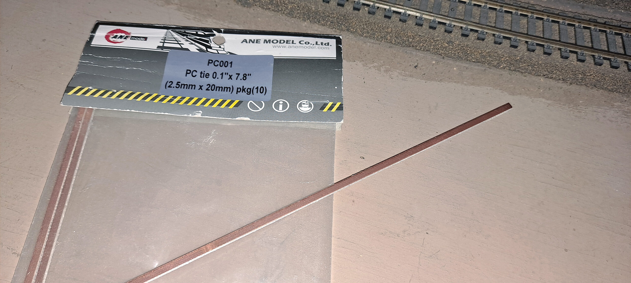
How to use PCB ties: Printed-circuit board (PCB) ties are pieces of printed-circuit board cut to railroad tie shape. They’re available for most popular scales and are great for areas where you need to ensure track stays in gauge.
A common use is for scratchbuilding turnouts. They’re used around the frog to keep the closure rails, guardrails, and frog all in position, and to hold the point rails together as a switch rod.
They also come in handy for ensuring alignment on modular or sectional layouts where tracks have to cross from one piece of benchwork to another, or for swing gates and lifts spans.
The reason they work so well in these situations is because of how they’re made. Printed-circuit board material has a thin copper cladding adhered to a non-conductive surface. The copper cladding is usually on both sides of the substrate, so this can sometimes require a little extra work. The copper cladding allows the rails to be soldered in place, ensuring they won’t move out of gauge.
Let’s take a look at a recent repair I made on the staging tracks of the Model Railroader staff’s Milwaukee, Racine & Troy layout.
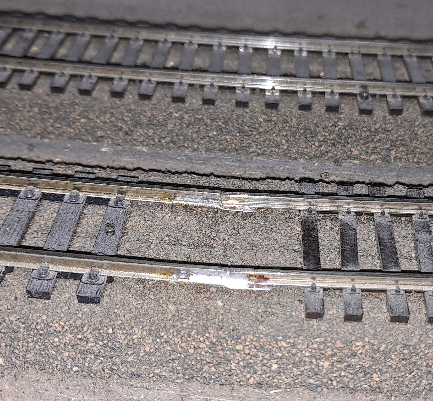
While moving a train into staging, it derailed at this spot where the main line code 83 track meets the staging code 100 track. To make the transition, the builder flattened one end of a rail joiner, slipped it onto the code 100 track with the flattened end sticking out, then soldered the code 83 rail on top of the flattened rail joiner.
Since there was no support under this joint, it eventually got out of gauge. I knew a PCB tie would ensure the rails stayed where they needed to.
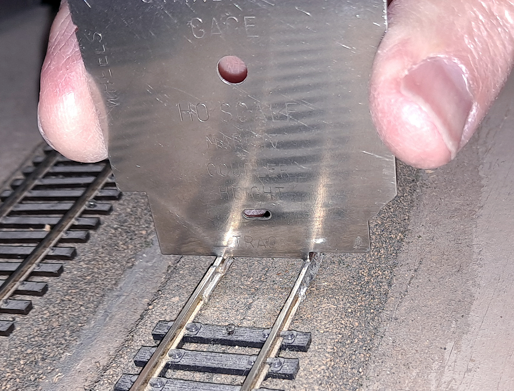
The first thing to do was identify the problem. I already knew where the derailment happened, and a National Model Railroad Association standards gauge showed me the gauge was too tight at the point where the different codes of rail joined.
Since PCB ties come in different thicknesses, I wanted to check how the material we had would fit. Everything looked good.
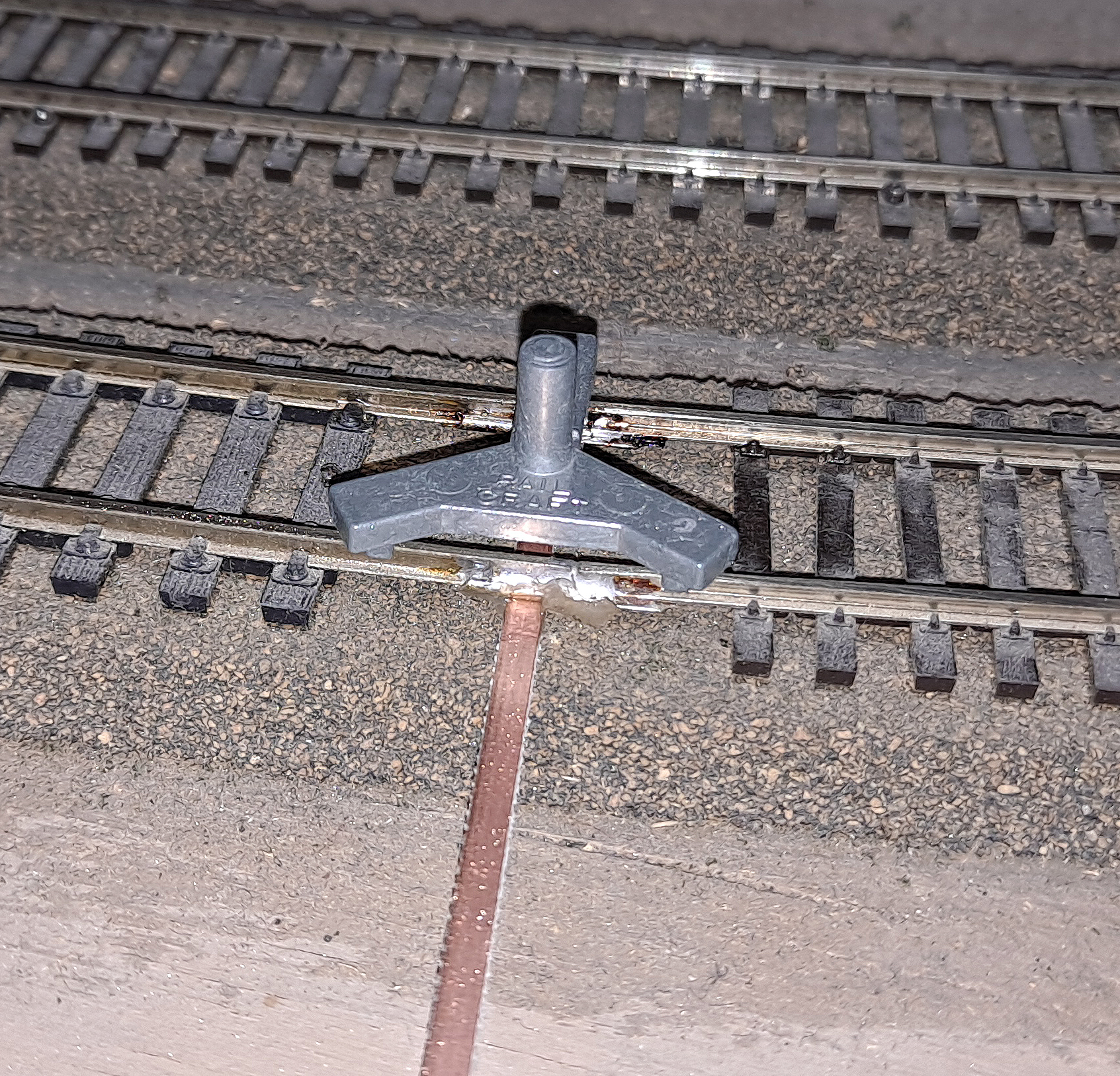
I used a three-point die-cast metal rail gauge to align the rails. I had to loosen the joint with a soldering iron, then I slipped the gauge in place before the solder cooled. This kept everything in alignment for the next step.
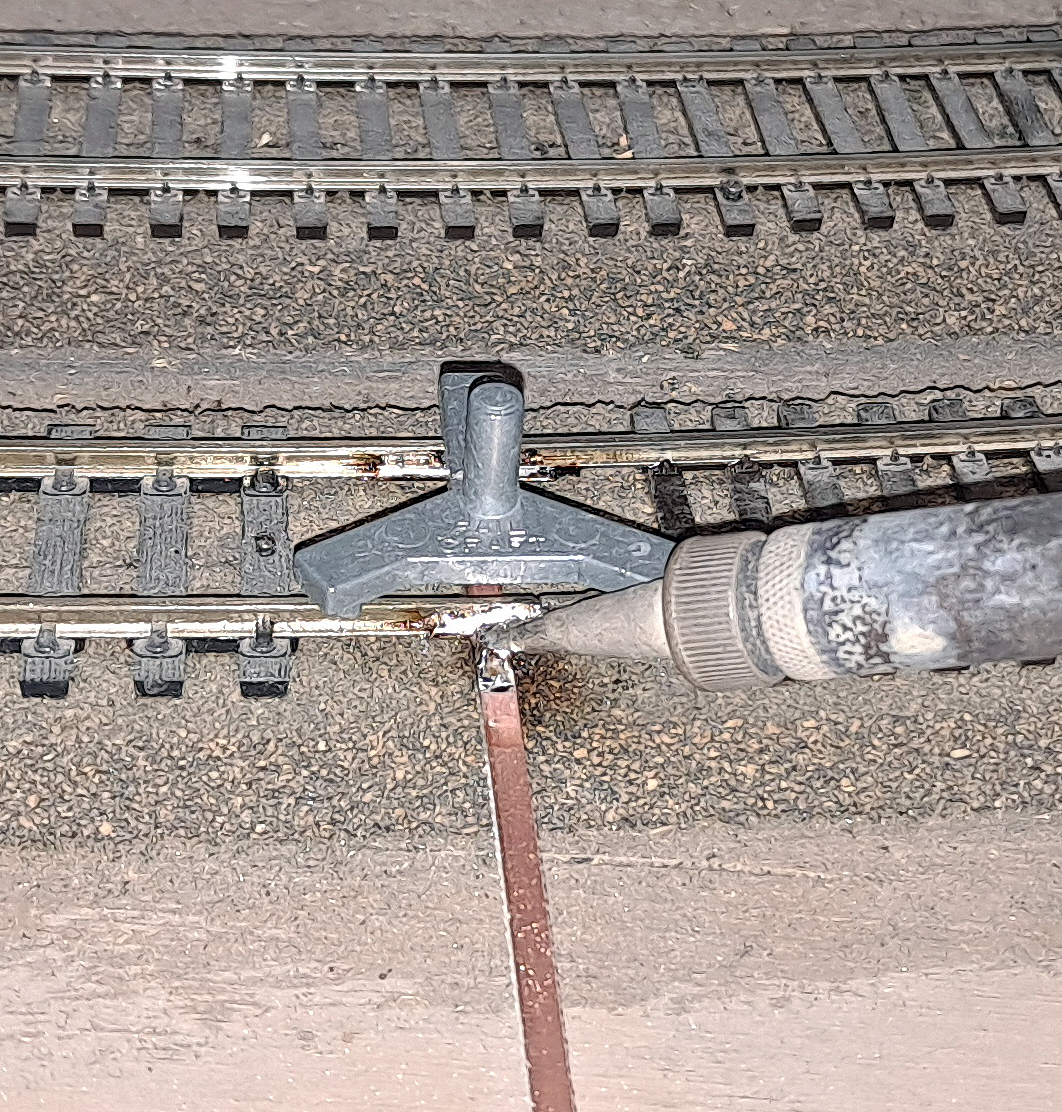
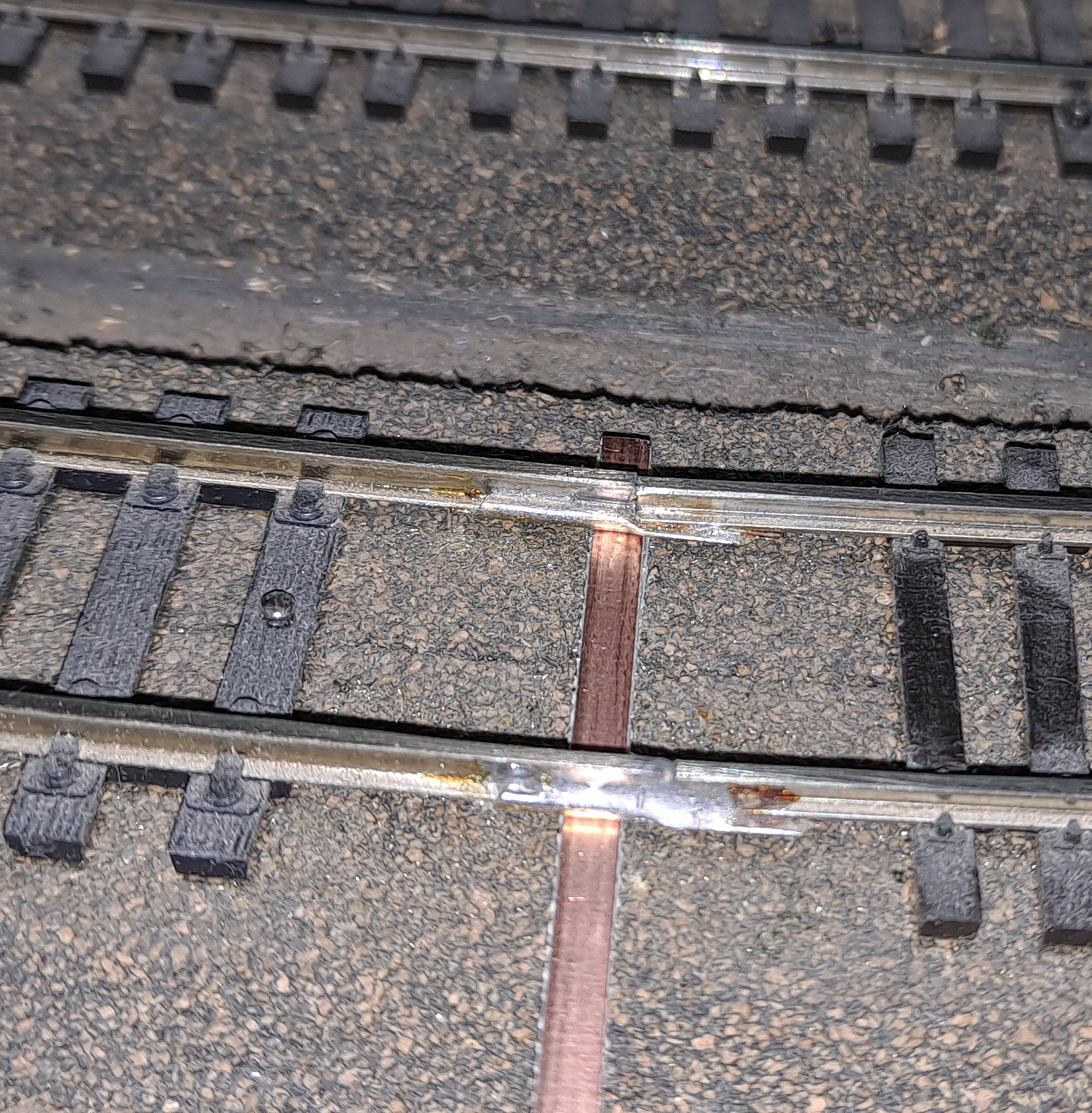
With the track in gauge, it was time to ensure it stayed that way. I slipped my length of PCB tie under the joint. I kept it long so it was easier to handle. Then I used a soldering iron to secure the tie to both rails under the rail joiners. I kept the gauge in position until everything cooled.
After the joint cooled, I flipped the gauge over so I could solder the other side.
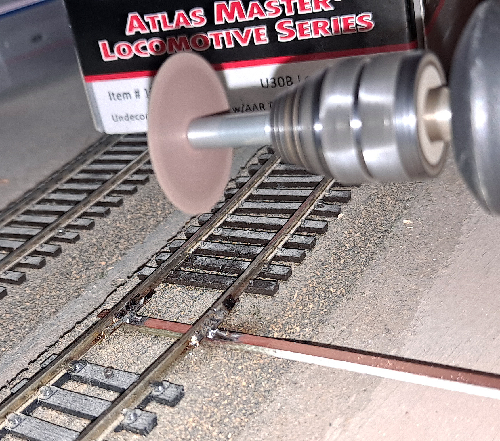
Once everything had cooled, it was time to trim and gap the tie. I used a motor tool with an abrasive cutoff wheel to trim the tie. Once I had an idea how quickly it would cut, I made a gap in the copper surface of the top of the tie. Don’t go too far into the substrate or you’ll weaken the tie and have to start over.

With the PCB tie trimmed and gapped, the track was ready to be put back into service. If this were on a visible part of the layout, I would have painted the tie to match the track around it.
If this were a location where the tie was going to be nailed to the subroadbed, such as at a gap for a movable section of a layout, or for a sectional layout, I would have cut a gap in the bottom copper cladding as well, so any spike driven through the tie to secure it didn’t create a short circuit.
With the repair in place, trains now enter and leave staging without derailing.
Looking for more Expert Tips? Click here.


This seems like an awfully lot of unnecessary work. For a lot less effort and a lot eaasier connection, try Atlas HO 551 Code 83 To Code 100 Transition Joiners.
¯\_(ツ)_/¯