


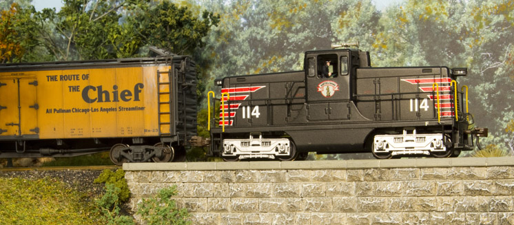
How to add DCC sound to a compact HO switcher: When Bachmann introduced an HO scale General Electric 44-ton switcher, I knew it would make a great addition to my Boston & Maine roster. The model includes a Digital Command Control (DCC) decoder, and I bought a version in the B&M livery. Out of the box the switcher ran well on my DCC layout, but it doesn’t come in a version that’s factory-equipped with sound.
I’d already added sound to a Bachmann HO scale 70-ton switcher several years ago and was happy with how that project turned out, so I decided to search for an appropriate decoder and add sound to my 44-tonner.
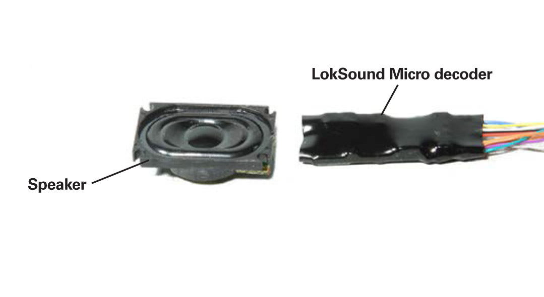
After researching the prototype, I found that most 44-tonners used two Caterpillar diesel engines. I found an ESU LokSound Micro DCC decoder, shown above, that was small enough to fit under the hood of my model. You can load the decoder with any sound in the LokSound library, including two Caterpillar D17000 diesel engines.
I ordered my decoder from Miniature Locomotive Backshop. The shop’s owner, Dugan Gorman, programmed all the specified sounds into the decoder for me before shipping. Along with the engines, I wanted a Leslie two-chime air horn, which was common on B&M 44-tonners. Since you must use a 100Ω speaker with LokSound decoders, I ordered a .64″ x 1″ (16 x 25 mm) LokSound speaker to fit under the hood of the switcher. This speaker is also shown to the right.
Disassembly
The model includes an exploded isometric diagram, which was a helpful guide during disassembly. After removing two screws from under the locomotive’s fuel tank, I lifted the body shell off of the chassis. I labeled the front of the chassis to make reassembly easier.
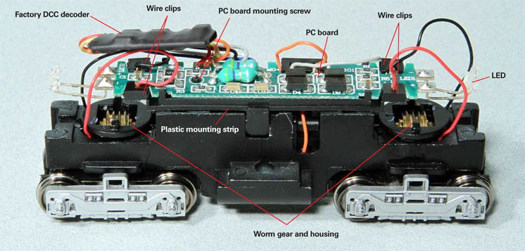
The image above shows the Bachmann decoder, printed-circuit (PC) board, and truck assemblies. Plastic clips hold the motor and truck wires to the PC board. The light-emitting diode (LED) headlights and decoder are soldered to the PC board, which is attached to the chassis with a screw. I removed the PC board, decoder, and LEDs, which were no longer needed.
Two plastic clips hold each truck’s worm gear housing in place. Gently squeezing these clips let me lift off the housing. The truck then dropped free of the chassis. I repeated this procedure with the other truck. The universal shaft came out with the trucks.
The PC board sat on a plastic strip that I removed. I reused the strip during the sound decoder installation.
With the wires free, the final step was to lift the motor out of the chassis. I made sure to label the front and rear of the motor, so that I could install it correctly during reassembly.
Modifying the chassis
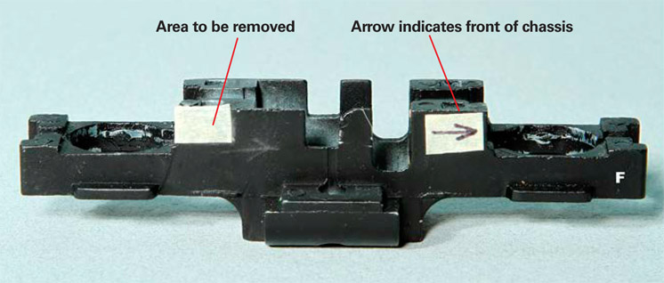
I mounted the LokSound decoder on the chassis and placed the speaker and new golden-white LED headlights inside the body shell. To allow the speaker to fit in the shell, I had to remove some of the die-cast metal chassis. I marked the area to be removed with a piece of masking tape.
With the chassis in a vise, I used a hacksaw to cut away the marked area of material. Then I smoothed the cut edges with a mill file.
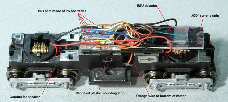
Next I put the truck assemblies, motor, and universal shafts back into the chassis. I cut the plastic strip that had been under the PC board to fit the modified chassis and attached it with cyanoacrylate adhesive (CA). I used this modified piece as a mounting location for new homemade bus bars.
Installing the decoder
For decoder installations in tight spaces, I’ve found that it’s easier to make all wire connections to homemade bus bars, rather than have a lot of bulky shrink-wrapped solder joints. For the 44-tonner project I used lengths of PC board ties cut into short bus bars. I needed nine wiring locations: one each for the red and black truck pickup wires, one each for the orange and gray motor lead wires, one for each speaker wire, one for the blue common wire, and one each for the white and yellow headlight wires.
After laying out the bus bars and checking the fit, I attached them to the shortened plastic mounting strip with contact cement. It’s important to make sure there’s space between each bus bar so that there are no short circuits. I taped the LokSound decoder to a .030″ strip of styrene that I’d cut the strip to the same length as the decoder. Then I attached the decoder assembly to the mounting strip.
I soldered each wire from the decoder to the appropriate location on the bus bars. Next, I soldered the wires from the trucks and motor to the bus bars. At this point, I tested the locomotive to make sure that it ran properly.
Headlights and speaker
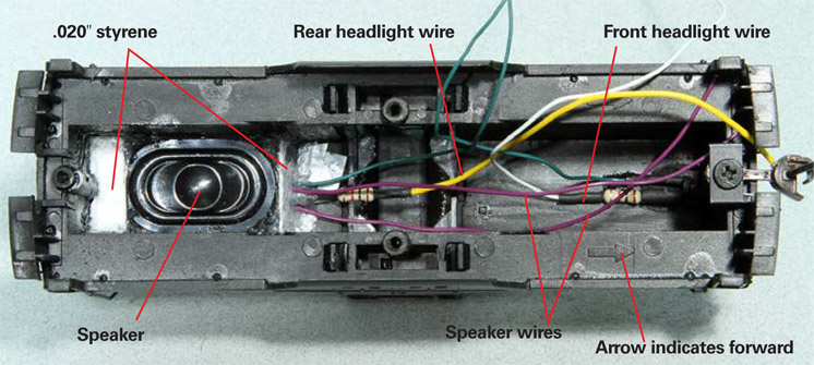
Instead of reusing the factory light board, I attached the LEDs to the inside of the body shell with five-minute epoxy. Each LED is wired to a 1KΩ 1⁄4W resistor. The white wire is to the front headlight and the yellow wire is to the rear headlight. Since I didn’t have any blue wire on hand, I used green wire for the common.
After soldering purple wires to the speaker, I had to fit it into the rear hood of the body shell. (Note that the front of the body shell is marked by a molded arrow under the front hood.) I trimmed the edges of the speaker surround until it just fit between the sides of the shell and slid into place just below the LED, resistor, and wires. This space created a sound chamber behind the speaker. I tacked the speaker in place with two drops of CA.
The next step was to seal the sound chamber. First I cut a strip of .020″ styrene to fit between the top of the speaker and the end of the hood. Then I cut another strip to fit between the opposite end of the speaker and the roof. I also cut notches in that strip for the LED and speaker wires. Once satisfied with the fit, I ran a bead of clear silicone caulk around the perimeter to finish sealing the speaker. This step enhances the speaker’s sound quality.
Final assembly
With the LEDs and speaker in place, I trimmed the wires to these components so that they would reach the bus bars without too much excess wire. This is important so that the shell fits on the chassis properly.
Once cut to length, I soldered the common wires together and then to their locations on the bus bars. I followed the same procedure for the white and yellow headlight wires.
With the wires soldered in place, I put the locomotive on the track and tested the sounds and lights. If there’s a problem it’s easier to fix at this point before screwing the shell back onto the chassis.
Satisfied that everything worked, I reattached the shell. Then I replaced the factory air horn with a Leslie two-chime horn casting. I now have a good looking, smooth running, and sweet sounding 44-tonner on my layout.
Looking for more information on how to add DCC sound to your locomotives? Watch Trains.com Director David Popp dive into adding a DCC sound decoder to a OO scale Bachmann steam locomotive.


Nice article-very well laid out. I am now (retired and) in the process of re-acquainting myself with my collection. The varied and sundry ‘menege’ of locomotives will, I am sure, keep me hopping (yeah, I know: Take the train…)
I’m glad this article was still accessible as I just did the same conversion following these steps. However, instead of removing the existing circuit board, I simply un-soldered the existing decoder and soldered in my replacement (Soundtraxx in this case to match my other locos), eliminating the steps needed to replace the headlights. Instead of the oval speaker I used a minicube.
NEAT! Nice work. I need to do this! Just as a caution to readers, while older ESU LokSound decoders use 100 ohm speakers, the newer decoders now use an 8 ohm speaker like everyone else.
Excellent project! Well done!