


Managing the installation of a Tortoise switch machine on my layout’s two-inch thick foam baseboard has been challenging.
I tried the hook-and-loop fastener solution explained in the October 2005 Model Railroader but didn’t like the wobble or the actuating wire’s long reach through the foam board. After some experimentation, I’ve developed the mounting method that’s shown in the illustration.
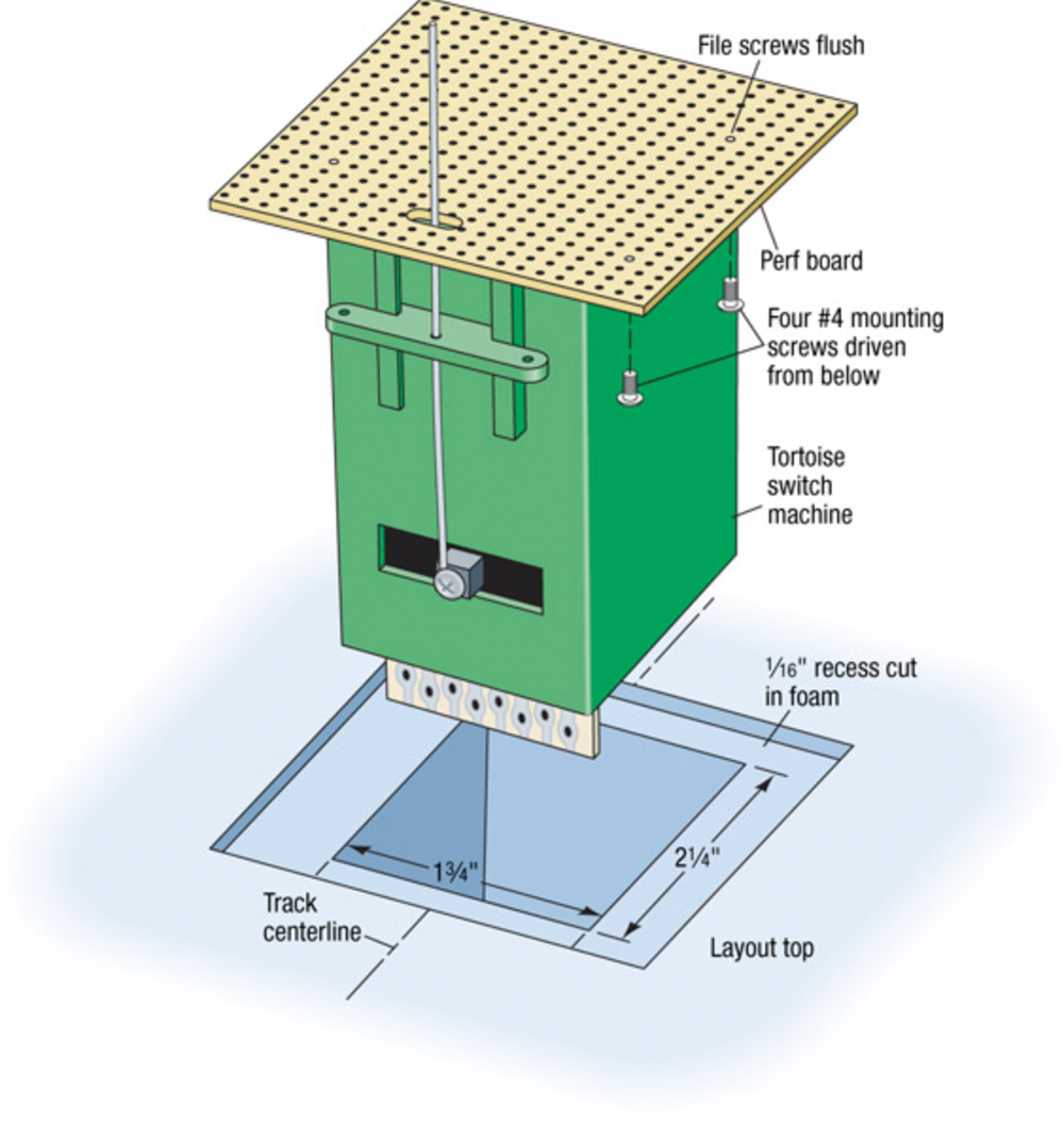
I mount my Tortoise machines on 2½” squares of perfboard, a tough insulation material that’s punched with a .10″ grid of holes spaced for integrated circuit components. RadioShack sells perfboard for use in breadboarding electronic circuits.
I center each switch machine on the perfboard and mount it with four no. 4-40 round-head machine screws. Then I drill a ¼” hole through the perfboard to clear the actuating rod.
Next, I cut a 1¾” x 2¼” rectangular hole through the foam table-top so the hole is centered under the track centerline and the actua-ting rod’s motion is unimpeded under the switch points. I drop the machine into the hole, mark the perimeter of the perfboard, and cut a shallow recess 1/16″ into the foam board so the perfboard is level with the top surface.
Finally, I use white glue to secure the perfboard to the foam. The roadbed goes over the motor, and ballast hides the perf-board edges. Once the glue hardens, I have a solid installation with a short actuating rod. It works beautifully.
To see an installation of a tortoise switch machine, watch Model Railroader Editor Eric White’s Tortoise Switch Machine topside installation.


this looks almost impossible. you have almost zero tolerance for switch point location. You must know exactly were the switch will be which means the track is already installed including the roadbed. What do you do, pull everything up to place the switch machine? I'm just asking.
Guys, and Gals,
To clarify on this technique. For Free-mo modules back in 2000 using 2" blue foam was the norm. We needed a technique to mount a tortoise switch machine onto foam and still have the legs be able to fold up, that meant using Mr. Puckett's method would yield exposed switch machines when the module is transported. This was a lingering problem for us.
While the technique has been traced to Harry Wong circa 2001 and Bob Schrempp 2007 using perf board and sheet styrene respectively, they are slight adaptations. Originally (I can't take credit for this approach either..I'll explain) When Brian Kreimendahl (a cohort of mine and associate editor to RMJ), and I were working on a solution, we used initially single sided copper clad.
Why single sided copper clad?
Initially the presumption was to use the bottom of the PCB (copper exposed surface down-top of tortoise) as a way to help reduce the amount of feeders one would have to run to a turnout. Instead of 8 separate feeder wires for the 2 points, 2 closure rails, and 2 stock rails, and 2 for the tortoise SPDT contacts to flip frog polarity. We were to isolate the copper clad into 2 halves down the middle of the board, drill holes where the rail was to run and run short feeders, soldering the bottom of the feeder to the copper clad and then fold up the top of the feeder to the foot of the rail. This was going to really simplify and speed up turnout installation. The tortoise had a very nice low profile and very little of it exposed to being damaged while module transported.
Maintenance was a consideration. The simple way was to cut the area around the tortoise a little bit larger then necessary to give room for a screw driver to access the fulcrum and mounting screws. If needing to be replaced, simply unscrew the 4 mounting screws and the tortoise dropped out from the board. (this was the only time I had to work upside down 😉
The entire turnout/PCB/Tortoise assembly could be done on the bench ahead of time making fine adjustment easier (I hate working upside down). This approach didn't come to me one night, like the flux capacitor did to Doc Brown in that movie "Back to the Future." No, It came from Model Railroader from a late 70s-mid 80's issue I apologize I can't find the original article date or author that deserves credit (I will look through my archives and follow up-he deserves recognition). His article was how to install turnouts from the top down rather then from the bottom up. EUREKA!!! Hey, working right side up is A LOT easier 🙂 he was using PFM or RIX solenoid switch machines, if I recall. I took his approach and adjusted it a bit for a tortoise then figured "Hey, maybe this PCB can help reduce some feeders a bit to two"
Realizing, that the PCB reduced feeder concept was good for every instance that didn't involve having to lay cork roadbed between the turnout and the PCB holding the Tortoise. We eventually scrapped the copper clad PCB and went with just the bare (no copper/solid-no holes) board at my well stocked electronics store (Not RadioShack). Harry, and Bob, ran with my adaptation but they couldn't find the same board I was using. They went with the easier to obtain from RadioShack "perf board" and Bob went with styrene.
If you can find it, use the solid no holes stuff, not the perf board. It's stronger then perf board/styrene and won't melt when you are cutting the screws off like the styrene.
If you like the idea of doing most of the wiring and adjusting on the bench, like me, I recommend single sided copper clad, works great it makes adding feeders to a turnout pretty easy.
Now, there have been a whole lot of new approaches to mounting switch machines in foam (new smaller switch machines and mounting components available, mounting locations for easier access, etc.). Perhaps MR will want me to do a follow-up article to Mr. Berger's contribution 😉
My method, though similar uses a square of masonite with a hole cut in it for the acutatng rod. I place the screw heads on the side opposite the Tortoise and then glue this to the underside of the foam board using construction adhesive. Once this has hardened I then attach the Tortoise to the underside of the homosote square using the screw threads that protrude. This way I can easily replace a Tortoise and the mounting board is not buried under the turnout. It does require a slightly longer throw rod and it has to be made of slightly heavier wire which you can get at most hobby shops. When disassembled my last layout I literally had to rip the mounting boards from the foam and it took a lot of effort to do anod I never have had one come loose in use–Larry
About 30 of my turnouts use Tortoise switchmachines. I have had to replace three. In one the motor needed maintainace, which is rare fore a corless motor of this type. Two had wiper contact problems.
I would suggest using diluted white glue to bond the ballast instead of diluted matt medium, since the white glue will dissolve when soaked with water. The matt medium will not.
I would also suggest following Jerry Smith's advice about not soldering the turnout in place.
Very little, on the Peco machines it is in the center of the machine.
Are you able to adjust the fulcrum once the switch machine is in place?
Has anyone tried this method or something similar for peco switch machines? I ended up mounting them on the surface of the layout because trying to line up the control rod was becoming very frustrating.
I have a section of my layout that has 2" styrofome mounted on 0.25" plywood. I have mounted the tortise switch machine to the plywood and used a heaver gage wire (0.039") actuating rod. Works fine.
Good Article w/ a special thanks to J. Nason and R. Kingery for their additional comments to help 🙂
As someone already said, this method had been used by NorCal Freemo for quite a while now. I expanded on that method and made a router template for both cut-outs. I also use 1/4 inch plywood instead of the PC board. That means I can attach the screws from underneath and be able to remove the Tortoise from the plywood if that would ever be necessary.
Your right Donald! Tortise switch machines require no servicing! Just ask any one who has used them ( I for one 15 years) and they will tell you never. Wiring sometimes is a problem but the wire connects would be exposed and used a Card Edge Connector also.
Unless you are soldering your turnouts in place, you simply move the railjoiners back and remove both the turnout and the switch machine. You can make the switch machine and the turnout into a single assembly at your work bench and then install both from the top. This is much easier than crawling underneath the layout.
Interesting. We've been using this same method for years. See here for more photos of same.
http://www.pbase.com/tracktime/norcalf
About the re threading the rod thru on replacemen
if you were to cut a small piece of shrink wrap that would
fit over the piano wire you could put a piece of wire same diameter thru from the top
connect to the rod on the machine with the shrink wrap
and push it up and thru .
Just a thought hope it is helpful
I'd presume that there is access from below for when (not if) the motor needs servicing. To make that easier, it might be a good idea to (a) use hex head screws that can be turned with a nut driver, and (b) use a card-edge connector instead of soldering wires directly to the Tortoise.
The one trick I'm still trying to figure out when changing a Tortoise from below is how to thread the wire through the small hole in the throwbar. It can be very hard to see where the wire needs to go, when installing the new motor, esp with only a 1/4" hole thru the perf board.
Ed
I do something similar, but I wanted to be able to get at the fulcrum to adjust it as well as be able to get the motor out simply. In addition I have areas with multiple switches and 4" of foam.
Also, I wanted to position the switch machine where the switch track was, not the other way round.
My solution was to use 1/4" plywood as the base. It will cover a larger opening in the foam without sagging, and doesn't have holes for glue to fall thru. Here's what I do:
1. Cut the hole in the foam, making a lip to hold the 1/4" ply even with the top of the foam. Make the hole a bit wider than the foam and big enough to be able to get at the switch machines.
2. Hot glue the ply in place, put the road bed and track down, get it adjusted, but don't permanently mount the switch yet.
3. Center the points of the switch and drill a small hole thru the ply using the hole the control rod goes thru as a guide. Make sure the drill bit is the same size or smaller than the hole in the tie.
4. Remove the switch, put a long (6" or so) control rod in the switch machine and push the fulcrum all the way up to the top of the machine. Put the control rod thru the hole you just drilled, make sure the switch fits OK and then use hot glue on top of the switch machine to glue it in place. If you need to replace it later just give it a good yank/twist and it will come loose. By putting it in this way the switch machine is automatically centered under the switch points by the control rod.
5. Remove the control rod, push the fulcrum all the way down, and then drill a 1/2" hole from the top using the small hole you made before as a guide.
6. Replace the switch and the control rod, adjust the fulcrum as needed (Easier to do with a bigger hole to work in) and your done!
I've been using this method for over a year now and have not had any problems.
Joey
Tortise switch machines require no servicing. Just ask any one who has used them and they will tell you never. Wiring sometimes is a problem but the wire connects would be exposed.
I've been mounting Tortoise Switch Motors in much the same way for a while now. But I build the turnout and tortoise on a small piece of 1/2 plywood (cut to fit the turnout being installed) on the bench, test the whole assembly, make any adjustments required, cut a hole in the foam, set the turnout assembly into place, lay and connect the track to the turnout.
there has to be a better way.
I've putting them on top of the 2" foam for two/three years making the flat surface flush with the foam. I like your idea better as it requires a wider lip to rest/glue the perfboard to. I just hope we don't ever have to replace the tortoise.
Bill Gibson
I have used this method successfully. Not wanting to detract from Mike Berger's contribution, but the original idea that I followed was published on the internet by Bob Schrempp (find it here – http://www.pbase.com/bschrempp/tortoise). He provides great pictorials and instructions; also he uses small screws to secure the Tortoise rather than white glue.
It would seem that you would have to remove the motor, if necessary, from the top and, so, remove the track as well.
I just installed my first Tortoise switch machine this week. It went really well. One crazy thing I did to help line up the switch machine with the switch, was using the compass on my iPhone. I centered the compose on the switch and found that it pointed at exactly 60º. Then I lined up the Tortoise with the hole I drilled at exactly 60º beneath the table. It was all in perfect alignment and worked the first time. I guess there is as app for everything.
This sounds like it will work well… Thanks
Great method, and thank you for posting this. I am looking at this same issue with a module I am building.