


Why would anyone want, let alone need, a model railroad with more than one deck? It seems to me that many of us truly believe we “need” a larger railroad.
But rather than simply act on this basic impulse, it also took a bit of peer persuasion to help me see that a multi-deck layout was really what I wanted to design, build, operate, and, of course, maintain. Although many friends weighed in, Bill Darnaby and his successful double-deck Maumee Route layout clearly demonstrated the validity of a multi-deck railroad. Despite the extra time, effort, and expense involved in building such a railroad, I found that the rewards expanded quickly.
Building a multi-deck railroad is essentially the same as building two separate railroads. Since many of us have a hard time designing, affording, building, and maintaining just one, it pays to make a realistic assessment of your time, funds, dedication, and goals before following in our footsteps. Let’s take a careful look at the major considerations before charging into such a venture.
1. Doubling your investment
An extra deck (or two) means you can achieve twice the mainline run and twice as many towns or industrial switching locations. This becomes especially important for those who have discovered how interesting timetable and train-order operation is, since a multi-deck layout offers a lot of places for trains to meet and pass.
By adding one or more decks, you’ll obviously get more real estate for scenery, although that’s a mixed bag. More scenery also means more investment in materials and time to apply them. Those with long main lines, such as Bill Darnaby’s 10-scale-mile-long Maumee Route main line, have found that applying seemingly endless acres of ground cover gets old and expensive rather quickly. The trend toward narrow shelf layouts – maybe as little as 8″ wide in the stretches between terminals and towns – supports such economy while simultaneously allowing for wider aisles.
A second deck means that the money and time needed to build a railroad roughly double. You’ll need twice as much subroadbed, roadbed, track, wiring, lighting, scenery materials, and structures. Build one deck at a time, however, and that cost can be spread out.
2. Lighting considerations
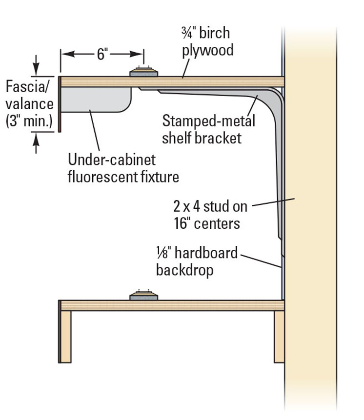
It’s wise to plan backward from the lower-deck lighting system you plan to install. As shown in the cross-section drawing, I use under-cabinet fluorescent fixtures with T8 or T12 tubes to illuminate my lower decks, and most fixtures are just under 2″ thick. (The number following the T is the diameter in eighths of an inch; a T8 is 1″ in diameter.) Where the upper deck is thicker at splice plates, I use thinner fixtures with T5 tubes, which are typically somewhat more expensive. They usually come with warm-white tubes, which are far too red for my tastes, so I replace them with cool-whites.
One day soon, we hope, the price of light-emitting diode (LED) fixtures will drop. I have tested LED fixtures ranging from 2800 up to 5000 kelvins on my Nickel Plate Road (NKP) layout, and the 4200K LEDs were a perfect match for cool-white fluorescents. Alas, I estimated 16 feet of such lights and the power supply would cost close to $500. But their long life, thin housing, and low heat output makes them ideal for model railroad illumination.
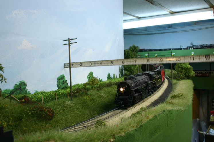
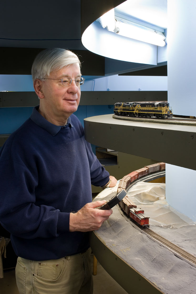
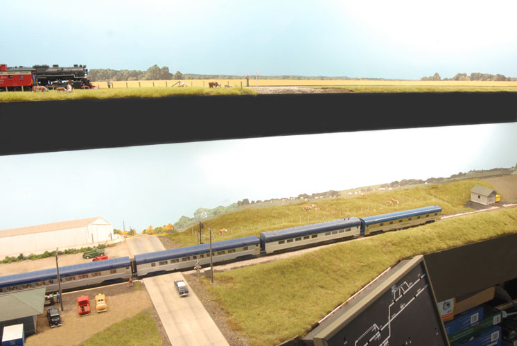
Layout builder Perry Squier uses 5000K fluorescent tubes and compact-fluorescent lamps (CFLs) to light the coal branch of his railroad. I find them a bit too “cold,” and they’re hard to get in all tube lengths and diameters, but they render colors almost perfectly. I assumed that the CFLs would, like incandescent bulbs, create pools of light below each fixture, but they light his railroad very evenly, even when the decks are spaced closely together. See the photo at right.
CFLs are somewhat “thicker” than under-cabinet fixtures, but their impact on deck spacing is minimal.
You can vary the wattage and perhaps spacing to accommodate various lighting-to-layout distances.
3. Deck spacing
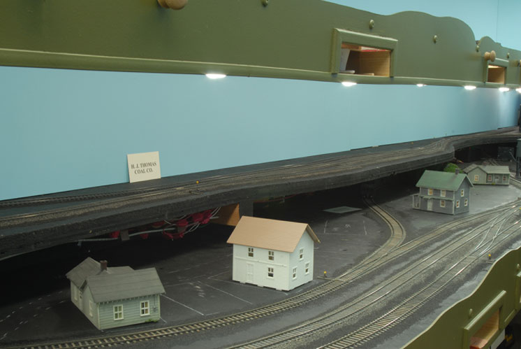
There is no magic number for between-deck spacing. The higher the two decks are above the floor, the narrower the space between decks can be. As the upper-deck elevation drops, it limits the view of the lower deck, although keeping the upper deck narrow will help.
I’d say that 10″ of clearance (not spacing) is a bare minimum. You need to be able to stick your head in between decks on occasion to install track, add scenery, and make repairs. Before settling on the minimum spacing, test it by mocking-up a pair of decks – a movable-shelf bookcase is handy for this.
But too much clearance is also a liability. A range of 12″ to 16″ is a good target; 18″ or greater spacing is beginning to force the lower deck too low and/or the upper deck too high. Again, mock it up to see how it looks to you.
A primary objective for an upper deck is to keep it thin. L-girder construction or spline roadbed is therefore not suitable for upper decks. I use ¾” birch plywood to ensure strength between supporting brackets and to support the under-cabinet lighting fixtures cantilevered from the outer edge.
Using 2″ foam board for subroadbed translates to a 1¼” handicap compared to plywood. The latter saved me enough space for under-cabinet fixtures without increasing deck spacing. Attaching under-cabinet or CFL fixtures to the foam would be tricky and add even more thickness.
4. Getting between decks
A major design consideration is how to move your trains between decks. Railroads with a long mainline run can climb gradually in a continuous spiral, which is the case on my Nickel Plate Road St. Louis Division. For shorter mainline runs, you can use a spiral helix, although that carries some baggage of its own. A few creative modelers have used elevators to raise entire trains between decks; see “Build a train elevator” by Steve Harris in the July 2009 issue of Model Railroader.
A general design goal is to have east on your railroad to your right with the “sun” behind you. That way a train crew can envision your layout as if it were a map with north at the top, or in this case north is away from the aisle. But if a train moves to the right as it enters a helix and exits in the same aisle at a different elevation, it will now be going to the left. You need to decide whether this is a concern and, if so, what to do about it.
The track in a helix also makes up a surprising percentage of the typical mainline run. If you use a 30″ minimum radius and can accommodate a 2 percent climb, then each turn of the helix will require 188″ [60″ x π (3.14)] of track and will gain 3.8″ [188″ x .02] of elevation. That’s good news, as we need about 3″ of clearance.
To gain, say, 15″ of elevation to reach the upper deck, we will need 4 loops around the helix. That means there is 752″ [4 x 188″] of track in that helix. That’s 63 feet!
If you use the helix as a place for trains to cool their heels to create longer runs between terminals, it’s a plus. But if crews have to twiddle their thumbs while trains ascend or descend via the helix, you’ll need to provide viewing ports to assuage their nervousness about a stalled or runaway train.
My entire HO layout is a continuous helix as it climbs from the east-end staging yard to west-end staging. The yards and towns are level so that cars don’t roll away. Obviously, the available mainline run is the key to deciding whether to climb between decks in a cylindrical helix or continuously as the railroad navigates around the room and one or more peninsulas.
As an example, let’s assume you have a 20 x 30-foot room, which is wide enough for a shelf layout with a central peninsula plus generous aisles. Let’s further assume that you have a yard or town along each long wall and on either side of a 20-foot-long peninsula on two decks. That translates to roughly 30 + 20 + 30 + 20 + 20 feet of railroad per deck. So once around the room back to the starting point allows a run of about 120 feet, or 1,440″.
Subtract from that the four dead-flat yards or towns per deck, each one 15 feet (180″) long. That’s 540″ [1,440″ – (5 x 180″) = 1,440″ – 900″] of climbing main line. If we need to have 15″ of spacing between decks, then the railroad must climb at 2.8 percent (15″ divided by 540″).
If you eliminate one town per deck, saving 180″ of flat railroad, that grade drops to 2.1 percent – still steep but manageable. On a flatlands railroad like mine, however, I doubt that most non-articulated steam locomotives could haul realistic-length trains in the uphill direction, but two- or three-unit diesel consists could handle it.
5+ odds and ends to consider
Here are few more key points to consider. You’ll find additional insights in my Kalmbach book, Designing & Building Multi-deck Model Railroads.
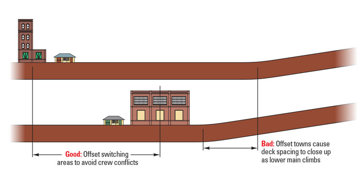
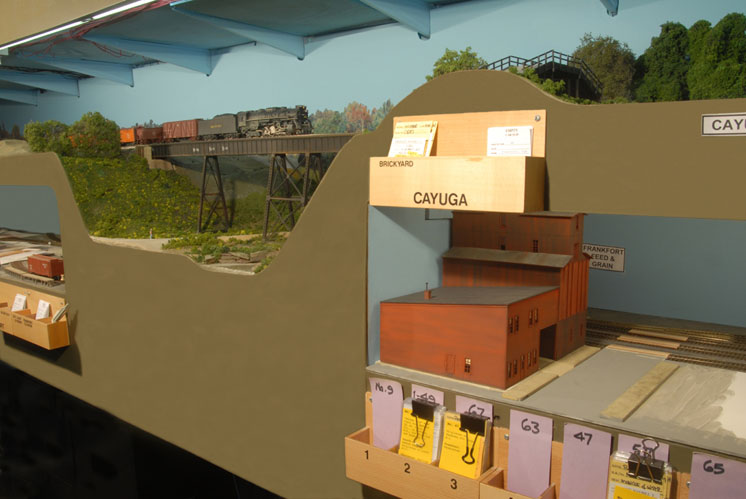
Switching centers. On a railroad like mine that climbs continuously except in towns, it’s a good idea to have zero-grade towns vertically aligned so that the between-town climbing segments remain equally spaced. But the switching centers of those vertically paired towns should be at opposite ends to avoid having crews get in each other’s way when working in both towns.
Wiring. The underside of an upper deck may be visible, and hence should be uncluttered. So I dropped feeders from the upper deck through the plywood subroadbed, then I routed them behind the backdrop down to the bus wires below the bottom deck.
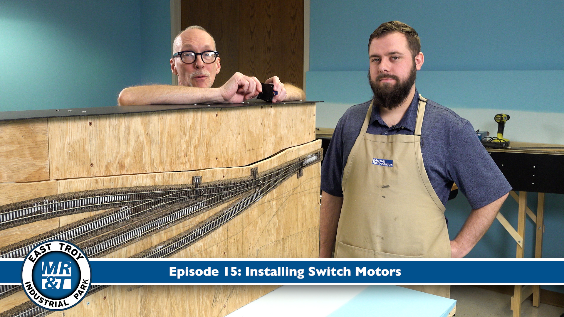
Switch motors. Switch motors hanging down from the upper deck may be visible, moreover, under-cabinet lighting fixtures may interfere with the installation of under-deck switch motors and mechanisms. I avoided this concern by using manual switch controls except in hard-to-reach areas of the two classification yards.
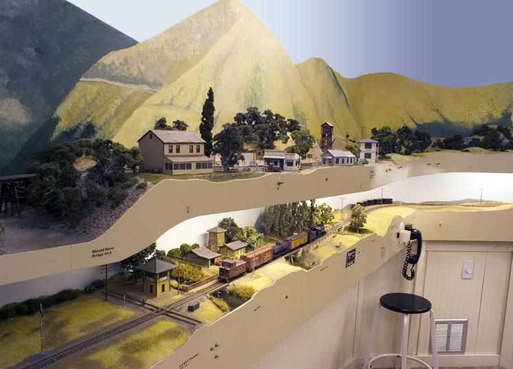
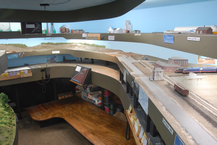
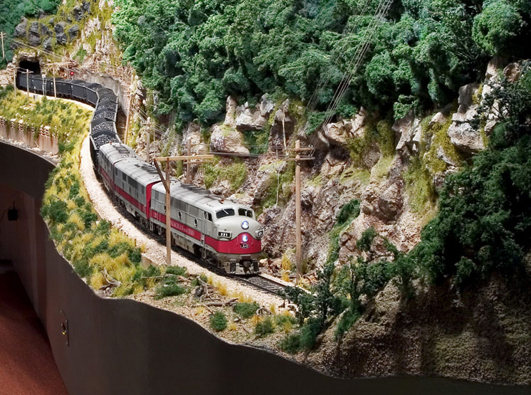
Deep scenes. Scenes of great depth are challenging to construct, especially on a lower deck. The use of mountain ridges or photographic backdrops will cut off views or fool the eye into seeing more depth than
is actually modeled.
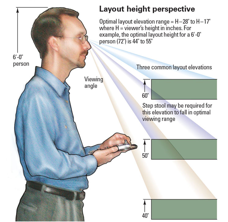
Viewer height. A continuous-climb helix like my NKP layout means that the track height will be ideal for almost everyone – somewhere. Everywhere else, the height may be lower or higher than each individual prefers. Decks connected by a helix can be flat, so you can choose which two elevations form the best compromise for most viewers. The higher the deck, the shallower the scene can be, as viewers look horizontally into the scene rather than down at it. But on an upper deck, a scene’s vertical depth can present challenging scenery problems.
Fascia. The upper deck’s fascia is the lower deck’s valance. This serves as a picture frame, so a thin – or no – fascia/valance is not a good design goal. I’d aim for 3″.
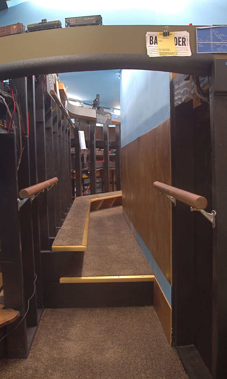
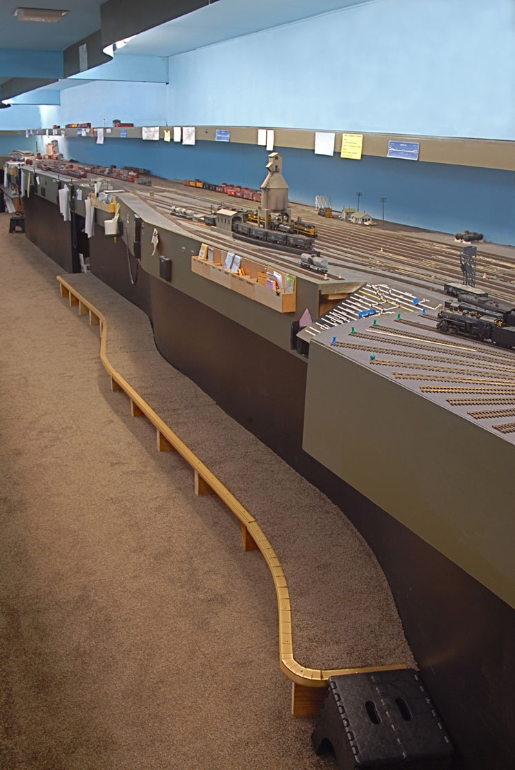
Steps and ledges. Elevated floors can reduce the apparent height of upper decks, and step stools can help operators reach in to uncouple cars. Where operators are required to lean into the railroad to uncouple cars or line switches, a low ledge is more secure than a step stool. Be wary of extended platforms unless railings protect the ends.
Grade considerations. Be sure your locomotives will pull trains of the desired length and weight upgrade and function smoothly as those trains descend the same grades. Build test gradients and curves prior to making final design decisions.
The brackets supporting the upper deck may cause the lower-deck backdrop to be almost an inch closer to the aisle. L-shaped carpenter’s squares make good brackets for wide upper decks.
It’s often a good idea to build the lower deck first and get it running before moving on to the upper deck. A section of operating railroad keeps morale up, and testing uncovers design flaws.
A laser level is ideal for setting elevation. Also use a digital level to double-check actual grades.


Depending on the “style” of railroad, it’s not necessary to subtract towns & yard sidings from the length of track contributing to the rise between decks. My favorite prototypical example of this is the town of Arrow, Colorado on The Moffat Road (D&SLRR), where there is a clear picture of the mainline continuing a steep grade, while the turnout into the town continues at a level grade. The design “rule” is that the mainline provides turnouts to level town stops or yard sidings, all stub end tracks that can be separated from mainline grades. The only exception would be passing sidings that must maintain the mainline grade, but these would not be used to spot cars. If a passing siding does involve a car spotting location, a turnout to a stub end yard siding is used to facilitate the level track. Of course on a point to point layout where the mainline terminates into a town or yard, that portion of the layout would be subtracted from the total track contributing to the rise. The critical aspect of the design rule is to ensure that mainline, presumed to be single track, is not blocked in either direction by a train at a town or yard siding. Additionally, this rule enforces the fact that no right of way exists in nature on a flat piece of plywood, and therefore the modeler must account for even minor variations in terrain that surrounds that track.
I am looking for an idea on how to determine how much incline and track radius to use for an over under arrangement. I am working in both HO and will be next going to S scale. My HO scale is using Bachman EZtrack should I be using a different different track to accomplish this plan.
THANKS GREAT ARTICLE AS PLAN TO BUILD TWO DECK LAYOUT IN FURTHER
Great article! I plan on building a multi-deck layout so I can operate both HO and N scale layouts in the same room. Plan is for shelf layouts to save room space.