


My little shelf layout is made from track and lumber salvaged from a small model railroad I was building in my apartment living room back in Pennsylvania before I moved to Wisconsin to work for Model Railroader. In my current living room, I only have room for a shelf layout, which is built into an entertainment center. The track is all Atlas code 83 using no. 4 and no. 6 Customline turnouts and flextrack.
The track is secured to the extruded-foam insulation board surface with foam-safe adhesive caulk. After working out my track plan by using the components I had in mind (easier to do when you’re reusing old track), I marked centerlines on the layout surface, figured out which of my old turnouts could be reused, then ordered new ones to replace those that were too damaged and to fill in gaps between what I had and what I wanted.
On a shelf layout, wiring and tracklaying go hand in hand. My layout is designed to operate with Digital Command Control (DCC) using an NCE PowerCab. In my case, most of the track is turnouts, and they’re the place to start.
Assembling the ladder
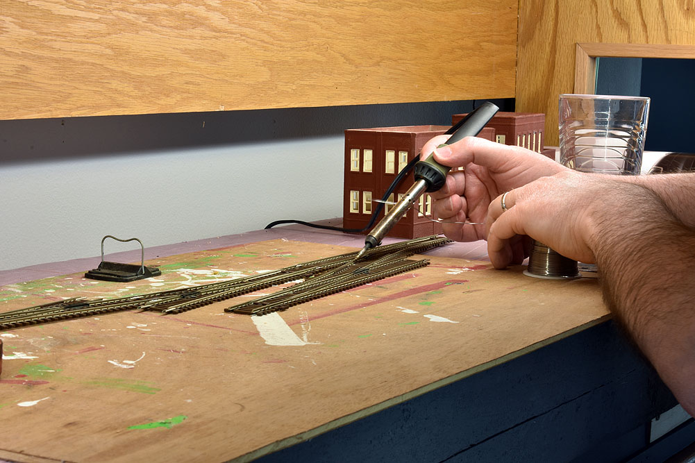
The first step was to assemble the yard ladder. As I put the turnouts together, I made sure everything was tight, then soldered the connection at the rail joiners. Remember, if you need to take something apart, just reheat the joint and slip the turnouts apart. The rail joiners might fill with solder, and the turnouts might need a bit of cleanup with a small file, but the turnouts are still good to go.
I like to solder on the outside of the rail. Solder should flow into the joint – you don’t want big globs. If it isn’t flowing, the joint isn’t hot enough. I used rosin paste flux and .032” diameter 60/40 rosin core solder. The soldering iron is a simple 25-Watt iron from Radio Shack.
Soldering wire
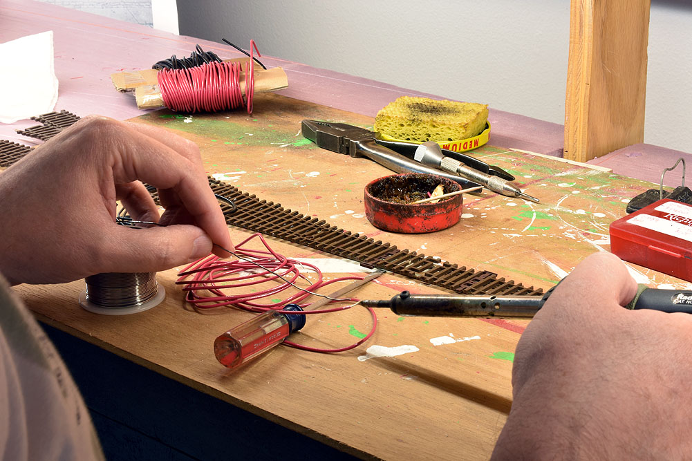
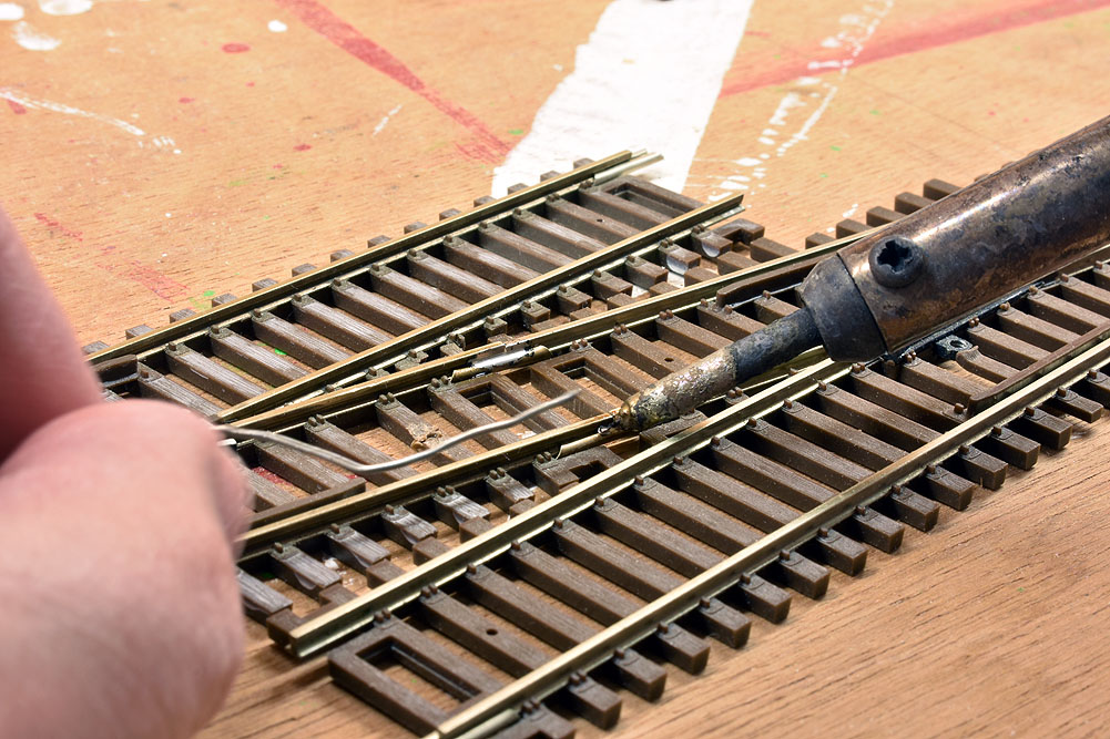
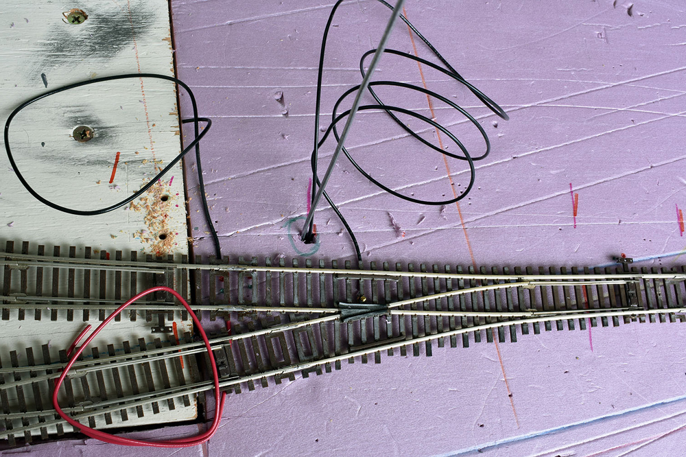
Once the ladder was assembled, I flipped it over and soldered feeder wires to the bottom of the rail joiners. The wire was left over from an earlier project, and it’s stranded, possibly 18AWG – overkill for this use. After twisting the strands together, I tinned the tip for a faster connection at the rail. If you’re buying new wire, choose solid wire, 20AWG or 22AWG.
Once the tinned wire cooled, I bent the end to a 90-degree angle, placed it on the bottom of the rail joiner where I had smeared a little flux, then added heat until the solder flowed. Sometimes, having a drop of solder melted on the iron’s tip helps heat transfer faster.
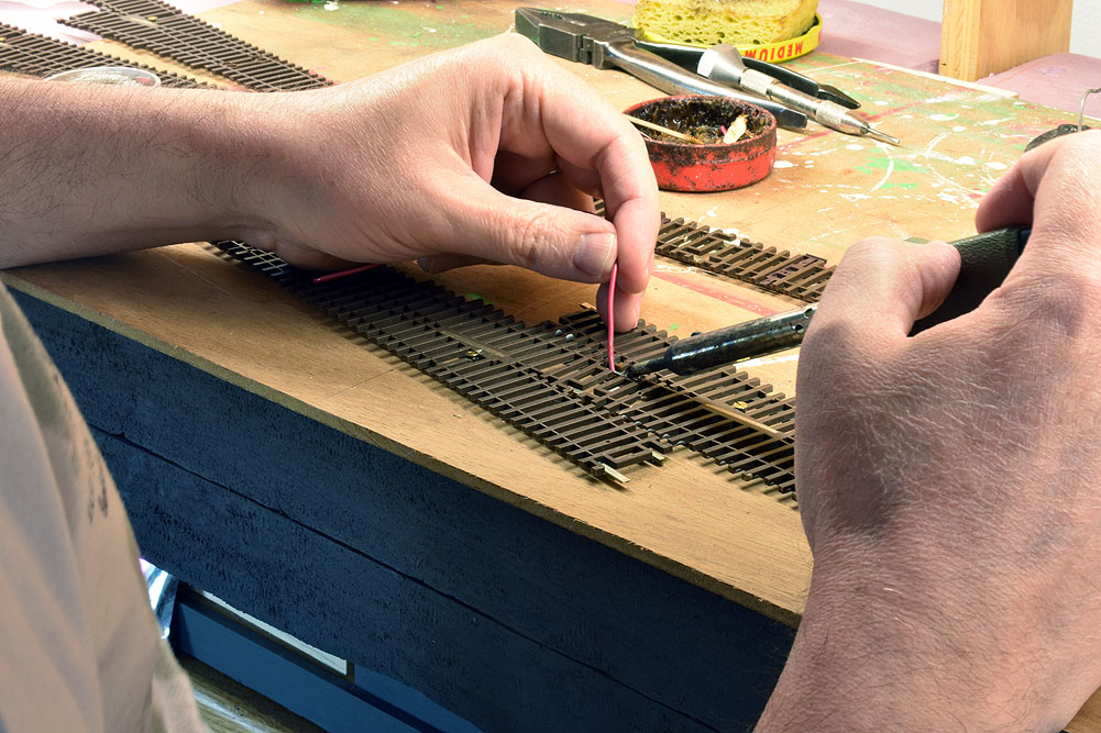
Dropping feeders
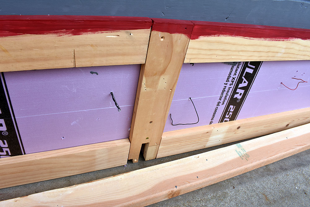
The surface of my layout is two layers of 2” extruded-foam insulation board glued to a frame of 1 x 4s. At the ends and in the center, I have plywood reinforcements where the layout attaches to the entertainment center cabinetry and also serve as a mechanical connection between the foam and the frame. I used a 1/8” “aviation” bit to drill through the 4” of material. Of course, two of the wires had to go through the plywood.
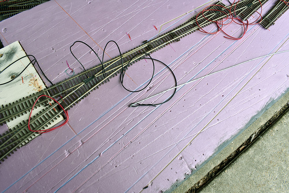
To feed the wires through the foam, I took a length of 14 gauge baling wire, bent one end into a tight loop, then wrapped the feeder around the baling wire. The baling wire was stiff enough to push the feeder wire through the foam.
Making connections
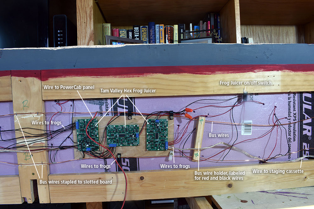
Here you can see the finished wiring. For the bus wire, I stripped the insulation off some old house wiring, probably 14AWG – again, a bit of overkill. The bus wires are stapled to the slotted board and threaded through 1x scraps that I glued to the foam. Then I soldered the feeders to the bus wires.
You may have also noticed the three circuit boards. They’re Tam Valley Hex Frog Juicers, screwed to a piece of 1/4” lauan plywood that’s glued to the bottom of the foam layout surface. Each Frog Juicer controls the frog polarity of six turnouts. Yes, there are 18 turnouts on this little layout.
Since I was in reuse mode for this project, the frog wires are all black. Not the best practice, but this is a small layout, so it’s not hard to keep track of them.
One extra detail is an on-off switch I mounted to the lower frame rail. This is so I can disconnect the Frog Juicers from the bus if I need to hook up a DC power pack to test a locomotive for work. This was a work-from-home adaptation that I expect will get little use in the future, but it does give me a place to test DC equipment before it gets a DCC decoder installed.
Attaching wires to Atlas die-cast frogs
To attach the frog wires to the die-cast metal Atlas frogs, I used a Kadee 2-56 tap set. I drilled the hole cast into the Atlas frog with the smaller diameter bit in the set. Then, using model railroad lubricating oil (make sure it’s plastic-compatible), I tapped the holes for 2-56 screws. If you haven’t used a tap before, here are some tips: Take it slow. Usually, a quarter to a half turn is as far as you can go before backing the tap out and clearing the metal chips. I use a pin vise to hold the tap, as it keeps me from applying so much leverage I risk breaking the tap. I usually have to tighten the pin vise with pliers so it grips the tap tightly enough.
With the holes drilled and tapped, I inserted short brass flat-head screws into the frogs, then soldered the frog wires to the screws. I found it easier to solder to the screws when they were in the turnouts, because they were held securely in the frog instead of having to be chased around my work space.


Hi Eric
What is you secret to striping the covers off the wire and not breaking the wire
Regards
John
What are you using for switch machines on the turnouts and how did you mount them to the turnouts in 4 inches of foam
Where’s the track plan. Eric?!