


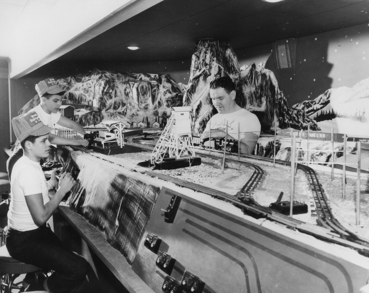
Staging yards are how we represent the rest of the world beyond the unavoidably finite portion modeled on our layouts. Trains that come and go from staging can be arriving from the next town down the line, the next division point, or the other side of the continent. Staging is invaluable to creating the illusion that our railroads are but a small part of the much larger continental rail network.
But what if you don’t have a lot of space in your train room to devote to a staging yard? You could represent the connection to the outside world with a fiddle track. A fiddle track is a track, usually leading to the edge of the layout, that’s long enough to hold an entire train. During an operating session this track is “fiddled,” that is, cars and perhaps locomotives are manually removed from and replaced on the layout as if they’ve arrived from elsewhere. While a fiddle track is simple to build, this approach has its downsides. Having to fiddle the track can take away time from more enjoyable aspects of operating, and moving cars with the “0-5-0 shifter” (your hand!) runs the risk of damaging details, smudging weathering powders, or even dropping models.
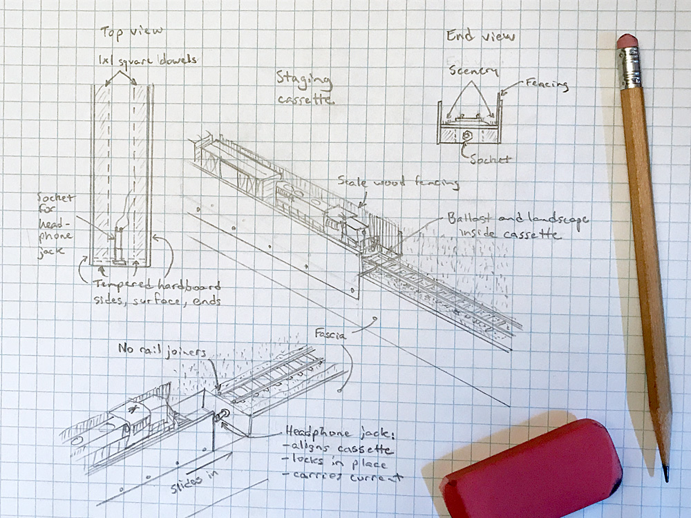
An interesting option for compact applications is the staging cassette. This is a small, narrow box bearing a stretch of track that plugs into a dedicated space in the layout. Multiple cassettes can be built, staged with trains (with or without motive power), stored on shelves until needed, and swapped in without the need to touch the rolling stock.
A cassette could be as simple as a plank of straight, furniture-grade 1 x 3 lumber with a track on top, enclosed on three sides with 1/8” tempered hardboard to prevent the train from tumbling to the floor while it’s being moved. Ordinary rail joiners could be used to align the track and conduct power. But these can be difficult to align and over time can bend and loosen.
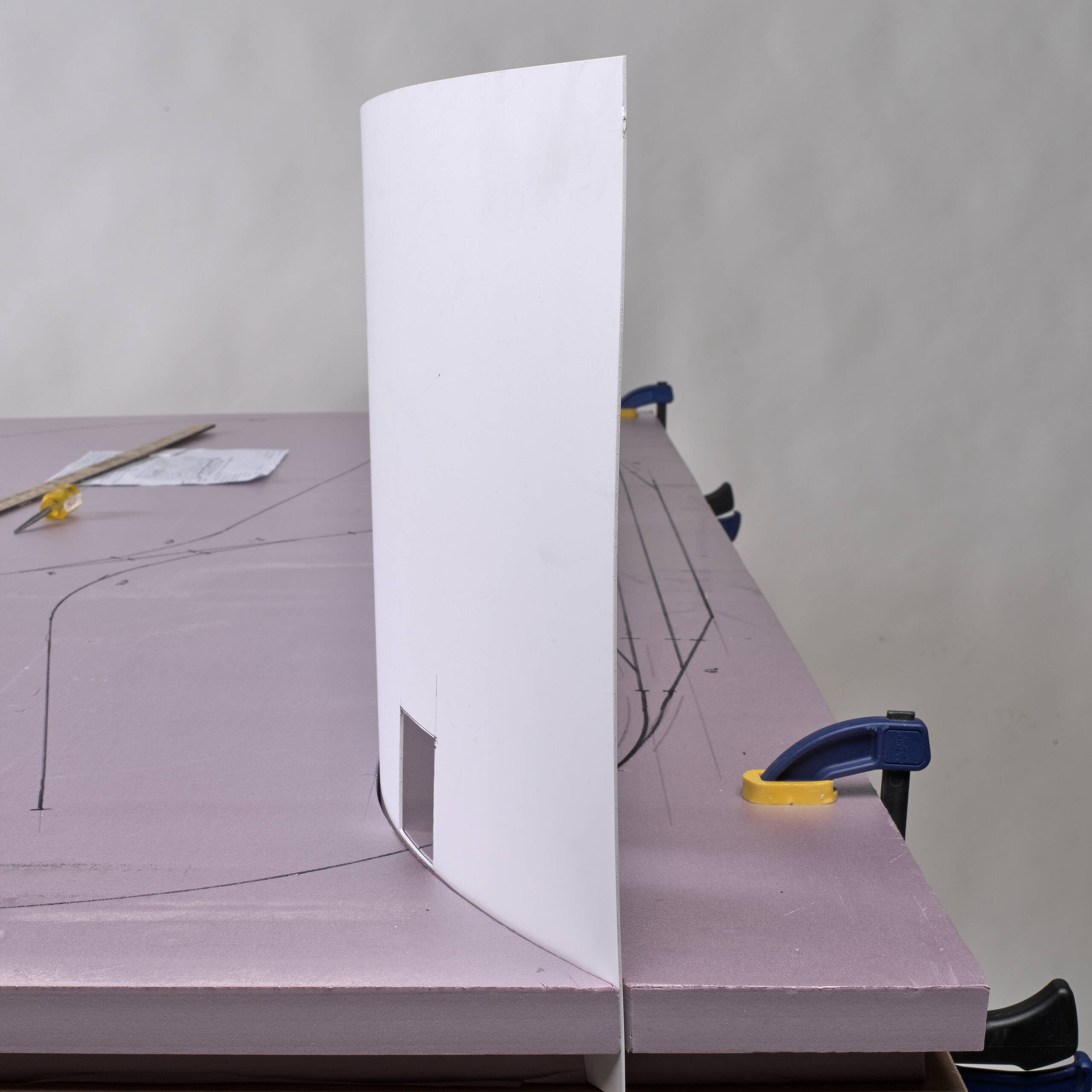
In the sketch above is a plan for a more complicated but more substantial cassette. Instead of a single plank, the base is a tempered hardboard box built on a pair of 1 x 1 square dowels. This leaves a gap in the middle of the base, into which can be installed a socket for a 1/8” stereo headphone jack. The corresponding headphone plug is installed in the end of the cassette’s slot in the benchwork and its contents wired to the power bus. This serves the triple functions of aligning the cassette; locking the cassette in place; and carrying electricity to the cassette’s rails. In this way, the plug negates the need for rail joiners.
It’s important that the tracks on all the cassettes always align with the corresponding track on the benchwork. The same is true of any situation where one track has to align with multiple tracks, like on a sector plate or transfer table. The trick to this is to always lay the single track first, no matter whether that track is the stationary one (the lead to a cassette, transfer table, or module attachment point) or whether it moves (a turntable or sector plate). Once the single track is laid, you have a reference point that all other tracks can be laid to align with.
Although it’s not strictly necessary, my design also includes some basic scenery to blend the cassette with the layout visually. Ground foam turf and ballast can make the base of the cassette look like it’s part of the layout. Cutting, staining, and gluing wood strips vertically to the inside of the tempered hardboard sides give them the appearance of wood fences, rather than a visual interruption to the scenery. Glue on some paper signs for more interest.


An interesting idea. I might recommend two small jacks, located on the cassette with the plugs on the layout. Two jacks would control rotational alignment of the cassette and the layout, for smoother operation. Also, it would assure that the polarity of the cassette is the same as the track of the layout. That way, if the layout is going forward, so is the cassette. That way, you don’t loose a train off the back end.
I would also recommend an attachment to the layout to support the cassette during operation. I have made a similar project on my Norfolk Southern S-Line in N scale. There I have a double main line, with three double line cassette on a rolling cart that is the same height as the layout. This provides a lot of staging for a 4 by 6 footprint.
Electrically, and possibly mechanically, and for parts availability putting the socket on the layout and the plug on the cassette might be preferable. Follows electrical principal of having power within female device.
Steve
I only see a Jack protruding from the end of the cassette. What is the mechanical connection to the main layout that supports the weight of the cassette and train?
In the lower left sketch is appears that the front edge of the layout has a sort of shelf on which the cassette rests and slides onto the plug.