


A while ago, I wrote about the Free-Mo modular standard. This month I thought I would share my thought processes while designing a Free Mo module.
I’ll let you in on a secret: We’re planning on building our 2024 project layout as a series of Free-Mo modules. So my goal here is designing a Free Mo module that we could actually build next year as part of our project railroad.
This complicated things somewhat. My planned module needed to be interesting, offer plenty of operating options, and demonstrate the benefits of the Free-Mo modular standard, but not be too costly in time or money (that is, no structure-packed urban scenes). As you can see from the crumpled-up drafts flanking my sketch, this was easier said than done.
My first draft was scrapped for being too rigid. The selling point of Free-Mo, as opposed to other modular standards, is that it only defines the modules at the end plates. In between those end plates, your module can be almost any shape you want. Make it any length, add curves, even include grades. But when I sat down with my graph paper and pencil, I took the easy route and drew an 8-foot-long rectangle with two parallel tracks down the middle. I wanted to include some natural curves in the main line, but those straight edges hemmed in my vision and didn’t allow the room I needed for the features I wanted.
Free-Mo modules can curve. A more free-form module could open up space on the outside of a curved main. Why was I starting with a rectangle?
My second draft showed more promise. A gentle curve mid-module (it’s got to be gentle, since the Free-Mo standard sets a minimum radius of 42”) gave me room for the yard I wanted on the outside of the curve. But again, I had mentally locked myself into a module of fixed width, with the main line right down the middle. Difficulty in fitting the yard in this configuration resulted in a sketch with too many erasures, so, try try again.
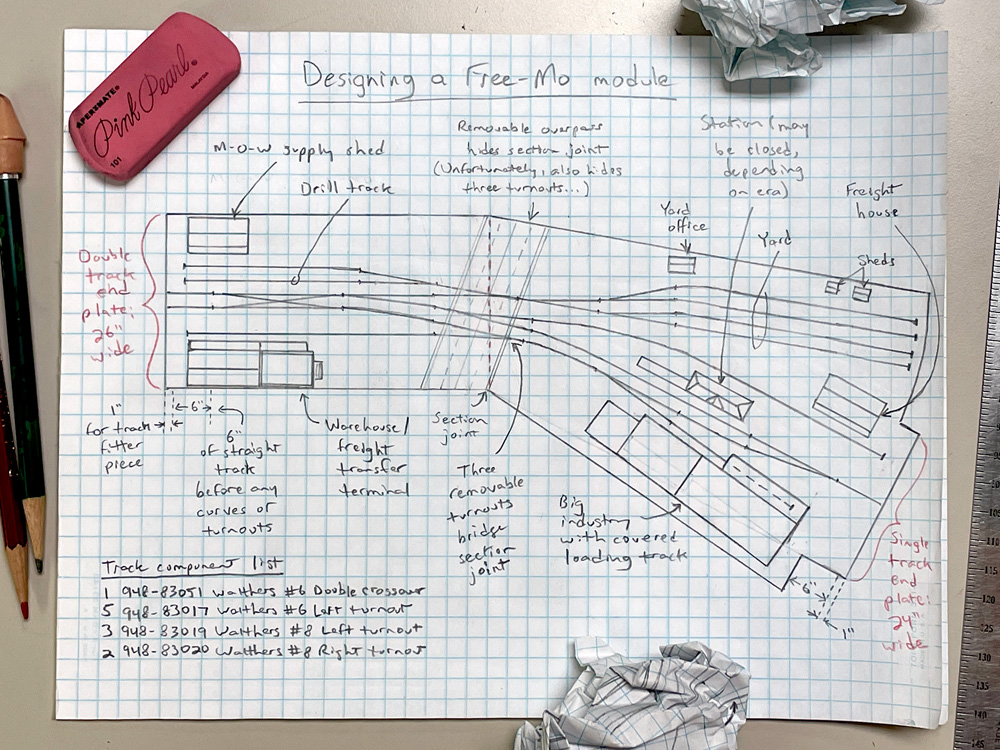
My third try at designing a Free Mo module gave me the plan I wanted. Let’s take a look at it.
The left side of the plan starts out fairly conventionally, with a 26” x 48” rectangular section. (The Free-Mo two-track end plate standard is 26” wide, with each track 12” from the edges. That way, it can join to another two-track end plate or a 24” wide single-track end, and the fascia will still match up on at least one side.) I wanted the other end to be a single track end plate, so this crossover gives trains a choice of exit routes. It also gives both tracks access to the passing siding.
Next was the no. 8 turnout leading to the yard. (Free-Mo says main line turnouts should be no. 8; no. 6 turnouts are allowed on sidings and in yards.) I put the yard on the straight leg of the turnout in order to begin the curve of the main through the diverging route. Adding a no. 6 turnout facing the other way gave me a drill track. This turnout shortened my yard tracks by about a foot, but that was better than having trains working the yard foul the main. A second no. 6 gave me another siding I could spot cars on. Since I envisioned the top side of the module as railroad property, I put a maintenance-of-way supply shed at the end of that spur. I’ll fill the empty space next to it with piles of ties, spare rail, line poles, and the like, making a cluttered, visually interesting scene.
A stretch of straight track after the first bend in the main calls for another turnout, this one leading to the front side of the module (as seen from inside the curve). This side of the module will have industries to switch. There won’t be room for many industries on the module, so to maximize the types of cargos that can be delivered here, I’ll make this a transfer warehouse.
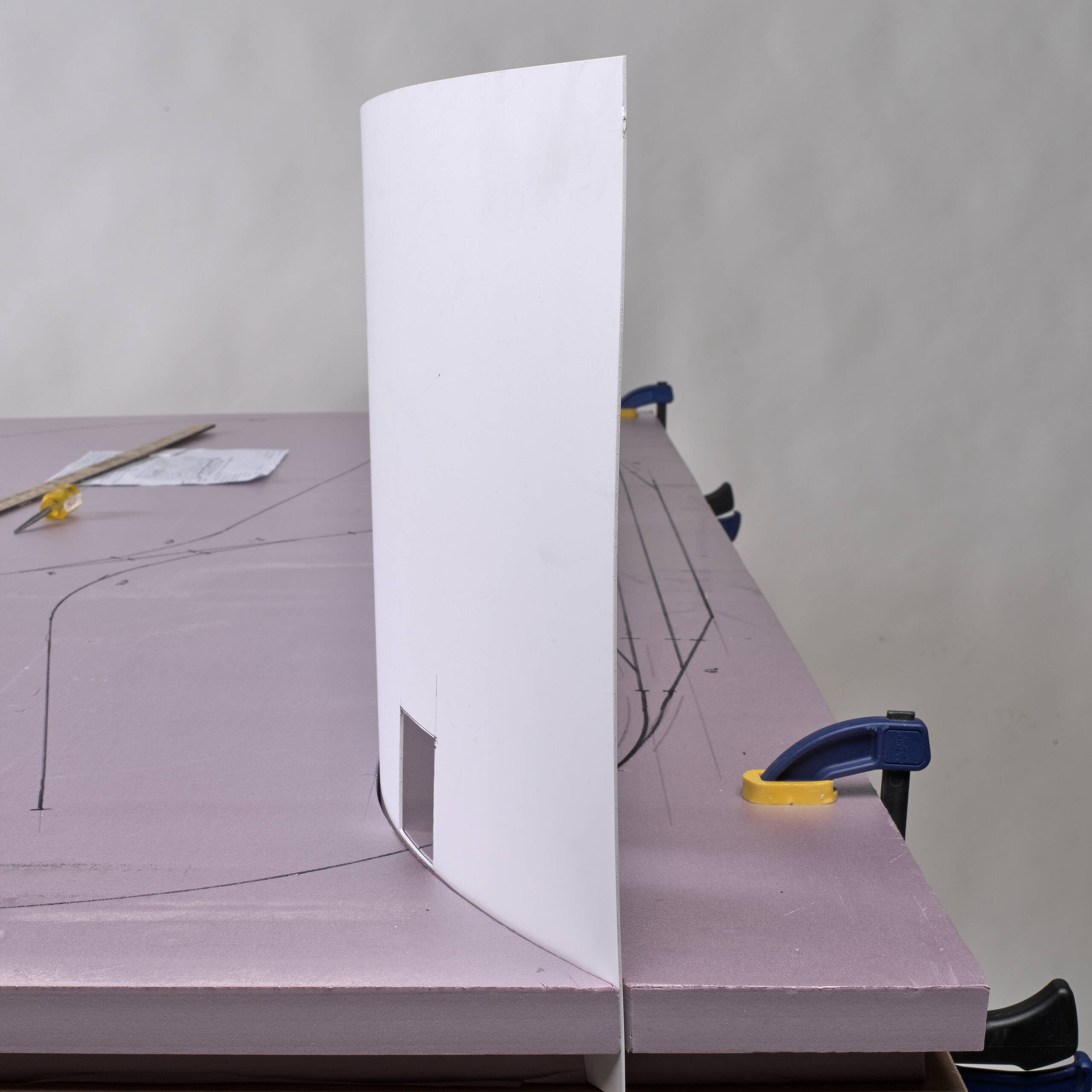
Now for a practical consideration. If we ever plan to take this module out of the building, say to exhibit it in our booth at Trainfest, it needs to be separable into pieces that will fit in our elevator. The place where the module turns from a rectangle into an angle seems like the obvious place for a section joint. The three turnouts across this section would have to be removable, which means they can be only lightly ballasted, if at all. A removable highway overpass will serve to disguise this and provide another dramatic visual feature. However, the overpass will make controlling the turnouts remotely with switch machines a necessity. Removing and replacing turnouts with switch machines is not something I’d like to have to do on a regular basis. Perhaps there will be a fourth draft of this plan that will turn it into two Free-Mo modules for simpler transport… or maybe we’ll just decide to never take it to a train show.
A turnout at the right end brings the main line down to a single track and turns the diverging track into a passing siding. I’ll add a small passenger station to make clear which track is the main. Depending on the era we decide our project railroad will be set in, the station may be active, used as office space or storage, or shuttered. A freight house at the end of the yard track is likely to be busy regardless of era.
A fan-type yard ladder makes a four-track yard practical. However, Free-Mo’s 42” minimum curve radius may make it hard to curve the topmost tracks to parallel the others. I might have to switch out one or two of the turnouts to right-handers and change the angle of the yard. If I do have to do that, I hope it won’t make the right end of the module too wide for the elevator doors. (Measurements taken during the design and construction of our HO scale Virginian project layout put that dimension as 3 feet, 10-1/2 inches.) A corrugated metal yard office, a few storage sheds, and a parking lot for some maintenance vehicles make our yard look busy.
Finally, there’s room for an impressively sized industry along the front right. Unfortunately, the track plan doesn’t leave enough length for more turnouts to serve this industry with multiple tracks. However, we can give the building car spots both inside and outside for operating variety. I’ll have to ponder what kind of industry it might be; a later decision on the locale we’re modeling will influence that decision. Regardless, this structure could be built with Design Preservation Models modular wall sections, Pikestuff corrugated metal modular walls, City Classics brick-and-concrete curtain walls, or a combination of these. I love kitbashing and scratchbuilding structures, so I’m calling dibs on building this industry!
So that’s the plan for the first of what could someday be three Free-Mo modules – this busy industrial scene, a rural one more centered on scenery, and a triangular junction/interchange. And who knows if there will be more after that? The real beauty of a modular setup is you can keep adding on as long as you have room.


Isn’t your right side module over 5ft? Couldn’t you move your break further to the right? That would make the right section a little smaller.
I’d eliminate the double cross-over on the left side. As is, it makes for a wicked S curve from siding to main. Is it necessary to have double track going to the left? Just wondering.
Consider controlling those 3 removable turnouts with a stiff but flexible wire in tube sleeves (guitar strings work well). A simple bend at the turnout end into the “throw rod” is usually flexible enough to get the turnout in and out of place. The control unit can be at the module edge and be a “machine” or manual, just as long as there is some spring action (also will help move the turnout end around).