


In an article in the August 2011 Model Railroader, I described a method to control yard ladders with a single rotary switch. By simply turning the rotary switch, all turnouts would automatically line up for the selected yard track. The method was based on using a bipolar power supply, Tortoise switch machines, and one SPDT contact on the Tortoise switch motor. A small number of diodes were also required, under certain conditions.
The article described the problem and then presented the solution for a few yard configurations. Although any yard pattern can be controlled with this technique, it isn’t readily obvious just how to arrange the switches and contacts for every situation.
So I came up with a simple six-step method that will guarantee a workable design for virtually any yard configuration. This method requires no formal training in Logic Design, so it can be used by any modeler who has a need or interest. I’ll describe the steps in detail and give examples of more complex yard configurations. But first, let’s see how the technique originated.
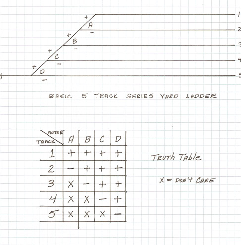
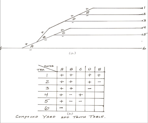
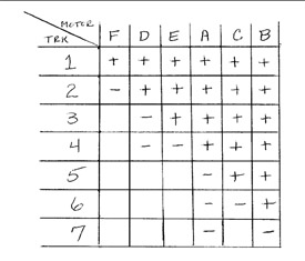
It all starts from the basic series yard ladder. Figure 1 shows a five track version along with its truth table. The labels on the yard plan are arbitrary – you can put the plus and minus signs in any order, as long as there is a plus and minus for each motor. Any two-state symbols can be used. We can use a1 and 0, true and false, or + and -. Here the plus and minus make more sense, as it directly relates to the polarity we will apply to pin 8 of the Tortoise switch motor.
Constructing the truth table is critical, so you have to understand how to do this. We simply make a blank matrix and label the motors across the top and the track numbers down the left side. Now we fill it in based on how the track plan was labeled. For example, to get to track 1 we need plus polarity on all four motors, so we fill in row 1 with all + signs. The third symbol used is the X for a don’t care situation. When going to track 3, we don’t care which way turnout A is heading, thus the X in box 3A.
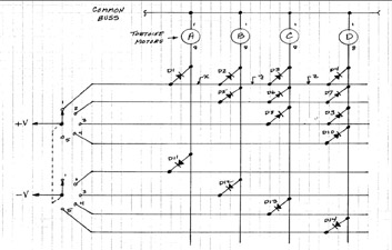
If you actually constructed the circuit in fig. 2, it would indeed control the yard ladder as desired. But note that 14 diodes are required. It is not so much the cost (as diodes are only about five cents apiece) as it is the time and aggravation of wiring up a full matrix. Worse yet, the number of diodes increases rapidly with more tracks in the yard. To figure out how many diodes you need, you sum up the numbers from 2 to the number of yard tracks. For example, a seven yard track would require 2+3+4+5+6+7 = 27 diodes! Mathematicians call this a Fibonacci series. This is the main motivation to look for alternative methods of control.
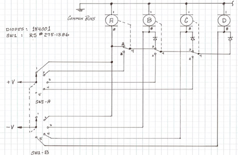
Now we need to make the first mental leap. If you stare at fig. 2 long enough, you will see that some diodes can be shared if another logic element is introduced. If you were to place an SPDT contact at point X that switched diodes D2 thru D4 to position 2 of the switch when A moved to position 2, you can eliminate diodes D5 thru D7! Similarly, placing contacts at points Y and Z allows the elimination of diodes D8 thru D10.
I do need to discuss the more straight-forward option. Here we just place four SPDT toggle switches on the panel and wire up each motor separately. From a wiring and conceptual point of view, this is certainly simpler. But from an operational point of view, it leaves a lot to be desired. I have operated layouts with multiple yards of seven or more tracks that were wired up with the simple option. It turns out that new operators constantly select the wrong route until they become familiar with the track plan. Invariably the owner of the layout has to station an experienced operator at the yard panel to insure smooth operation. It is your choice, but remember that wiring is a one-time effort but operation is forever.
Now that the preliminaries are over, let’s discuss the six-step design process.
Step 1: Sketch and label the yard track plan.
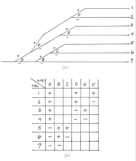
As an example of this process, I will use a compound yard track plan shown in fig. 5a. Although the plus and minus assignments are arbitrary at this point, the process will work out easier if the routes to the farthest tracks are labeled with plus signs.
Step 2: Fill in the Truth Table.
In fig. 5b I have created and filled in a truth table matrix based on the yard track plan and assignments generated in step 1. From now on, I will leave the don’t care entries in the truth table blank for clarity instead of using an X.
Step 3: Make the truth table upper triangular with respect to the plus signs.
This sounds like a mouthful, but I’ll explain the terms. Take a closer look at the truth table in fig. 1, and note that it has an interesting pattern. Minus signs are only located on a diagonal going from box 2A to box 5D. Everything above this diagonal are plus signs, and everything below is a don’t care situation. When a matrix is in this form, it is called Upper Triangular, for obvious reasons.
Here is an interesting fact about truth tables. You can swap rows and columns, at will, and it does not change the overall logic. But you do have to swap the entire row or column, along with its label. You cannot swap individual box entries. Here is the key point: we know the circuit realization for an upper triangular truth table. It is shown in fig. 2. All we have to do now is to re-arrange our truth table, by swapping rows and columns, until it looks as close as possible to upper triangular.
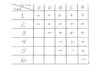
In case you are wondering, this step can be done with any yard pattern. You should end up with all plus signs above the diagonal and only a couple of stray minus signs below the diagonal. If you cannot, try swapping the signs on the turnout motor that is giving you problems and repeat from step 2. You will have an easier time if you enter the motor labels in the truth table starting from the far point in the ladder, and working towards the throat. In fig. 5b I deliberately did it backward to illustrate this.
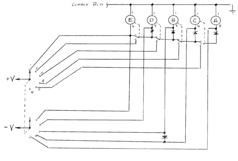
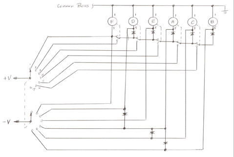
Step 4: Draw a preliminary schematic.
We now make a preliminary schematic that is exactly like the pattern for the simple series yard. Of course, you have to extend the pattern to match the number of Tortoise switch motors in your particular ladder. Now here is another key point. You label the motors, left to right, in the SAME order determined by your upper triangular truth table. So now you see the purpose of step 3. It determines the order in which the motors have to be connected, and which contacts go where.
So I don’t get things confused when it comes to wiring, I label each Tortoise switch motor according to the plan in step 1. Then I carefully associate the motors on the schematic with the correct motors on the physical layout. We are almost home free now.
Step 5: Add diodes to handle the missing logic.
Step 6: Wire it up, test, and install.
As I do my wiring on a fixture, I can test it before actually installing on the layout.
Final comments
The design algorithm presented here was chosen for its simplicity. It does not require a college level course in logic design to understand or apply it. Trained logic designers will note that it does have a small flaw. Namely, it doesn’t always yield the absolute minimal design. But it is only off by a couple of diodes. This is not too much of a price to pay for the simplicity.
If you like logic puzzles, you could see if a contact configuration can be found that eliminates some or all, of the extra diodes. But by the time you do that, you could have wired up a couple more diodes ten times over. As a challenge, apply this procedure to the second example in the Model Railroader article. You will come up with an extra diode. Compare this to the schematic in Model Railroader, which has no extra diode and is minimal in configuration. Let me know, there is always a better way to do something. I hope someone can find it.


I need a source and specs for the bi-polar ower supply used in this article
With one wire to the tortoise tied to ground via the “common ground” how can the polarity be reversed on the motor??
I am working through your article with interest. The pdf file would help a lot. Please send to bcarttar@comcast.net
Read tour article and found it an interesting way to make a small yard control without an oops.
Please send a pdf.com file to RDGCO2102T1jds@ yahoo.com so I can fully read an interpret the documents.
Above my pay scale couldn't understand a word of it.
Thank you for a great artical. I am in the process of planning out and building a new panal for one of our yards on our club layout. It has been changed and added to over the years as the yard evolved to its present arrangment to the point that no one understands how it works. I intend to use the rotary switches at both ends of the yard to simplify the panal. I would greatly appreaciate a pdf file. Please email to: tom@majorsite.com Thank you so much for your contribuations to the hobby.
Tom Lutrel
Like many other model railroaders, before I start wiring my ladder yard I would like to receive a copy of any pdf materials.
Thanks…
ricks.hive@zebra.net
pdf file please
rneilphoto@aol.com
Thanks, Richard
I built the bipolar power supply you described but the output voltages are low. Would you mind telling me what to expect? Should it be sufficient to power MicroMark Switchtenders?
Great article.
Bob
Dr. Hunt
Please send me a pdf of figure #2 I cant read the terminal numbers
thanks, mike
mskrocke@att.net
I cant read which terminal is # 2 or #3. Can you clear that up ?
I would also appreciate a PDF for Pt 1 and Pt 2.
kawix2@yahoo.ca
Can't wait to get started! thanks
Dr. Hunt, I found your article in the August MR on your yard
ladder control not only a great read but timely as well. If you
are still sending out PDF's on parts 1 and 2, could you please send them to reptile01@comcast.net. I believe one of the computers in my house can handle the high resolution PDF but would appreciate it if you could send both in case it does not.
Thank You, Geoff
Hi Mr Hunt,
I'll join the rest. Its a great article, but a pdf file would be a big help to me as well.
remtrains@gmail.com
This is an excellent article. I'd very much appreciate a PDF myself. Please send it to edbrandon@hotmail.com.
Much appreciated!
– Ed
I see you shared the part numbers for the switch and the diodes. Can you give a part number for the power supply.
thanks, mike
I intend to use your articles on turnout ladder control and have a hard time reading drawings in the online version of your design procedeure. If you are sending out high resolution pdfs of this article, please send one to charles.oberly@ctcn.net. Thanks for the trouble you took to assemble all the articles.
Mr. Bush,
All the modelers that have included an email address have received a copy of the pdf. Sorry to hear about your confusion.
Also, an error in figure 2 (Sept MR) for the four position wye diagram has been brought to my attention. The connection between Main-West and the -V should be removed. A correction will be published in the Nov issue of MR.
Best regards,
Dr. Tom Hunt
great article,I would appreciate a PDF file as well – obriendm@aol.com (thanks)
I see the comments! but did they receive there ..PDF's ???? and im just lost with it all !!
Hi Thomas,
It is a great article. I will use it. Would you also send me a pdf copy to dennis@mics.co.za. Also would you give the specs for the rotary switches?
Dennis
A very interesting article. A PDF file would be greatly appreciated; egdolezal@comcast.net.
Thanks
Please send .pdf file to radyson.1@att.net
Thank you
Richard.
P.S. Now wiring up yard ladders at club.
DR. HUNT: PLEASE SEND ME A COPY COPY OF YOUR HIGH RESOLUTION PDF COVERING YARD LADDER CONTROL USING SLOW MOTION SWITCH MOTORS. THANK YOU. SINCERLY, AL BANDUR E-mail: afbandur@aol.com