


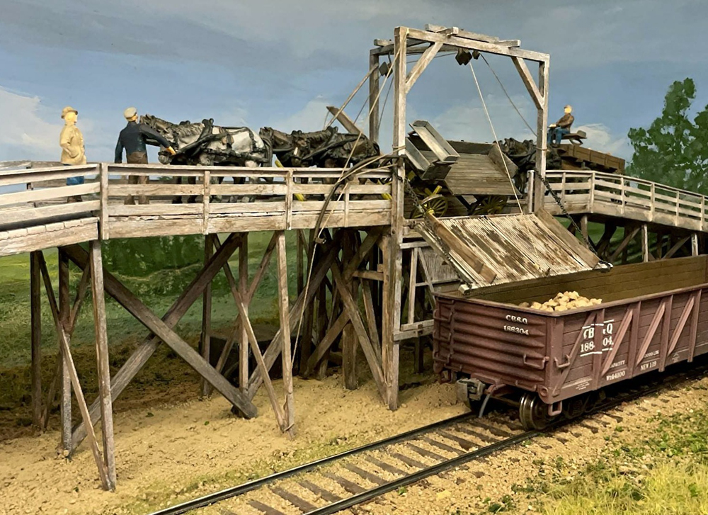
Sugar beet production and sugar refining was an important rail industry throughout the 20th century. Every fall, farmers brought their crops to nearby sugar beet dumps, where beets were loaded into railcars and rushed to sugar company factories.
In the early 1900s, sugar companies built tall wooden Carroll beet dumps to speed loading. At the top, horse-drawn wagons were chained to a delicately balanced tilt platform that tipped the wagon and spilled its beets into a railcar below. To avoid buying or shipping dirt, a grill-like beet spillway – the “Grizzly” – let loose dirt drop to a dust apron and collect in a bin below. Without the weight of the beets, the platform righted itself and the horse team pulled away.
Patented in 1896, the Carroll beet dump could unload a wagon every minute. In common use throughout California, Colorado, and many other states, it was a landmark of the sugar beet industry. Carroll dumps were also marketed for unloading coal, coke, grain, and ore from either wagons or railcars into ships, railcars, and bins. The Carroll dump was an important customer on early railroads, and it can serve as “industrial scenery” in a later era.
The inspiration
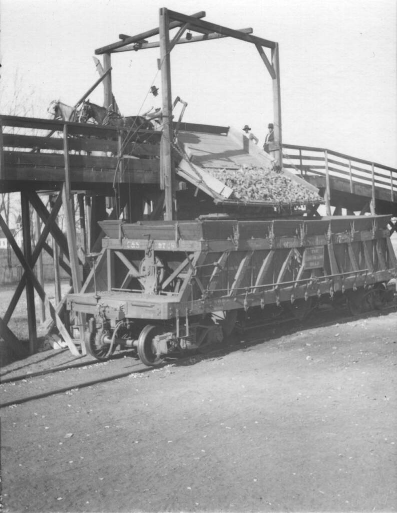
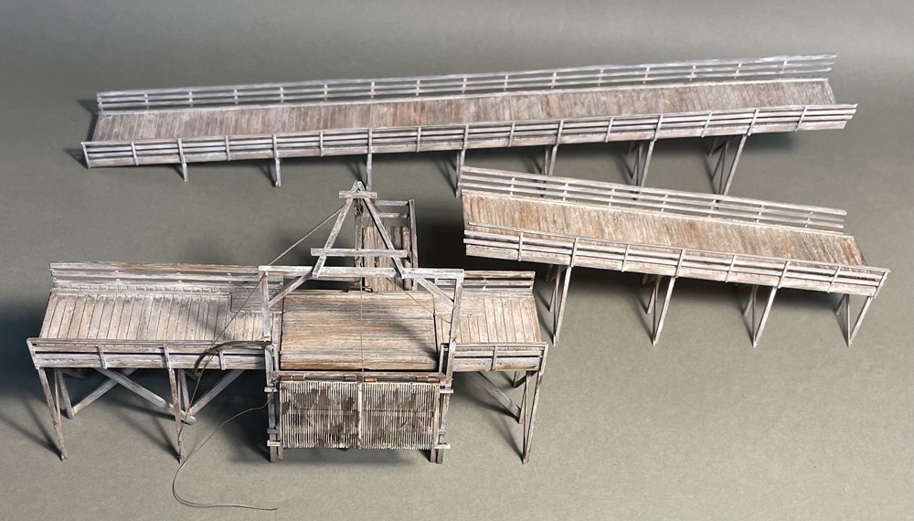
I scratchbuilt my sugar beet dump to match the prototype in Niwot, Colo., for my HO scale Colorado & Southern Ry. I created drawings, available in the .pdf with this article, from photos of the Niwot dump and construction plans for a similar version in Chino, Calif.
I textured and painted my model, made almost entirely of styrene, to look like weathered wood. The tilt platform tips, and the Grizzly drops and raises with a servo motor.
Drawing 1 in the .pdf shows the overall plan for this long narrow structure. The ramps are multiple 12 scale foot spans, with the lowest two spans simply mounded dirt. To fit my space, I didn’t model the entire approach ramp and concealed that end behind a grove of trees.
Easy as ABC…DE
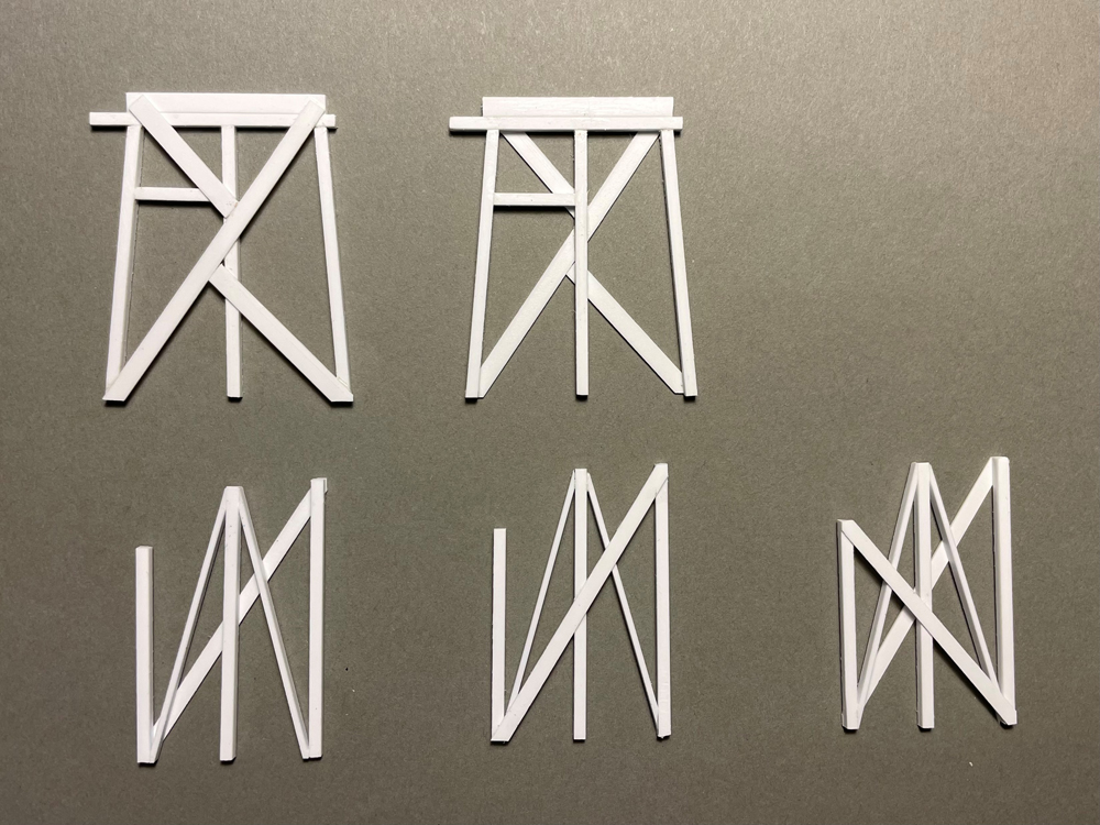
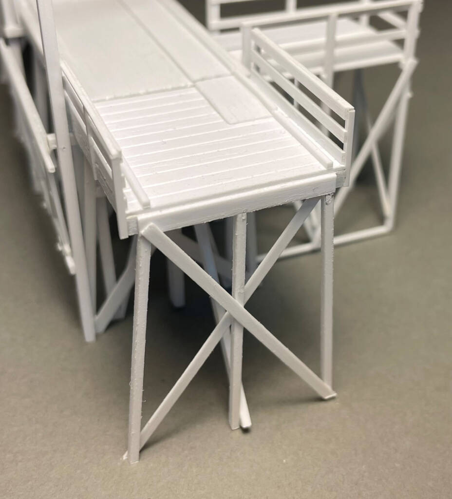
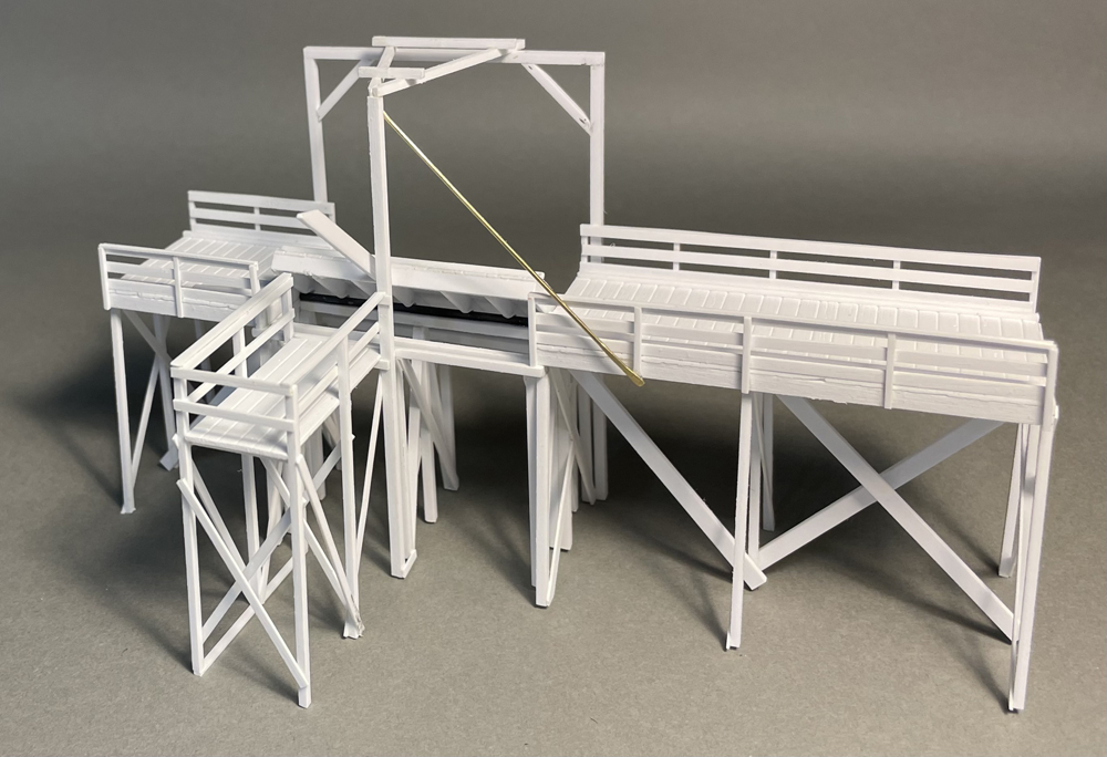
I began with the five special bents supporting the tilt platform, labeled A through E in order from approach to descent. Each bent is unique, as shown in drawing 2 and the photo above.
As is my habit for wood structures, I lightly sanded all of the styrene for this project with 150-grit sandpaper. I built the bents directly on the drawing for accuracy.
Starting with the A and E bents, I slightly rounded the edges of the .080″ x .125″ and .080″ square cap beams to make them distinct before gluing them together. After cementing the .080″ square posts to the double cap beams, I attached the .020″ x .125″ bracing and short .080″ square stop beam support.
For the B, C, and D bents, I glued the .080″ square posts to the common .020″ x .100″ diagonal brace. After 10 minutes, I added the six .040″ x .080″ center post braces and the unique C Bent .020″ x .100″ diagonal brace.
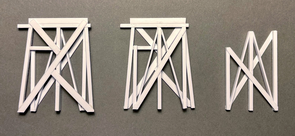
I combined bents A and B, and D and E as shown. Note that the bracing on these compound bents is on the outside. I was careful to align the B and D post tops. The pipe beam post is 2 scale inches shorter than the rest beam post.
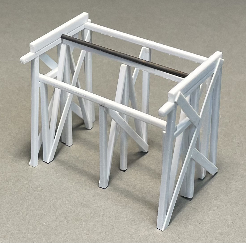
When cured, I sanded the post bottoms square and glued the compound bents upright in position on the main drawing. I then cemented the .080″ square stop/pipe/rest beams across them. Finally, I attached the C bent under the beams at the midpoint of the span, ensuring all was square.
Tilt platform
The tilt platform decking is a scale 10 x 15 feet, cut from .040″ thick .060″ spacing V-groove sheet with boards running lengthwise to the structure. See drawing 3 in the .pdf. I textured the styrene sheet and all the decking on this model using a three-step process. First, after cutting board separations through the edges, I sanded both surfaces. Then I scribed extra grain on top by dragging a razor saw blade in direction of the board grain. Finally, I chipped and nicked the edges, and stabbed in a few knot holes with a dental pick.
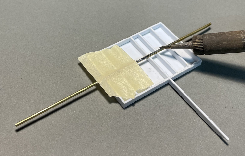
I cemented the .040″ x .125″ framing and lever to the bottom of the decking. The lever is 21 scale feet long and runs through the back framing. I cut the end at an angle. I also cut a small notch down the exact center line of the platform joists. After taping a 1/16″-diameter brass rod into the notches, I carefully heated it with my soldering iron and pressed it partially into the joists to form semicircular “bearings.” I had to trim a few bearings with a hobby knife so the platform could move freely on the rod.
After checking platform fit with the ABCDE bent assembly, I sanded the rod, cut it to just fit between the bents, and painted it Vallejo Model Color Black Gray.
I put a small drop of cyanoacrylate adhesive (CA) near each end of pipe beam and set the rod in the bearings. Aligning the platform into the bent assembly, I held the platform while the glue set, then removed the platform.
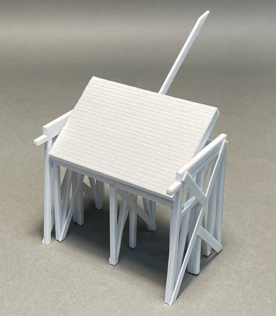
With the rod secured, I tested the platform. Though the tilt platform was secure, I could easily tip and remove it from the model.
Since the parts were still accessible, I brush-painted the ABCDE bent assembly Vallejo Model Color White in preparation for weathering.
More bent building
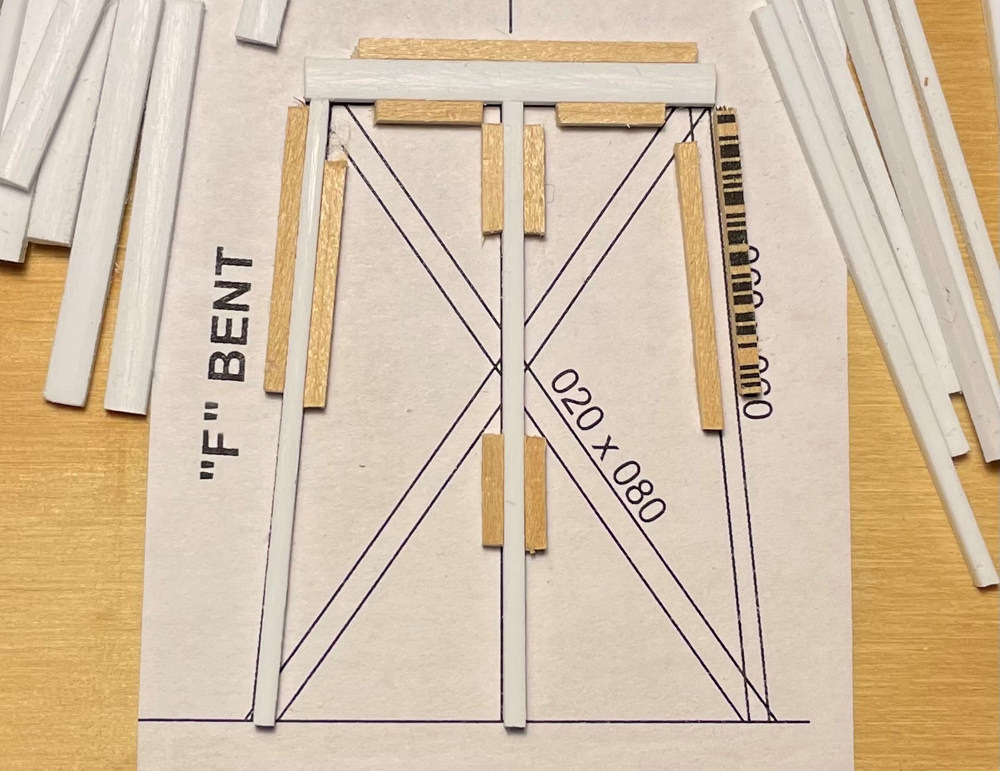
With 14 F bents to build, I made a jig to hold the styrene in position for assembly. I glued the F bent diagram in drawing 2 to a scrap of plywood with white glue, then placed a .060″ x .125″ styrene strip over the bent cap and glued 1/16″ square stripwood lengths to the drawing to hold it in place. I avoided getting glue on the styrene. I laid .060″ square styrene strip over the posts and glued stripwood to hold them as well, removing the styrene when dry.
I started each bent by cutting a cap beam to length. I subtracted the .125″ height of the bent cap from the bent heights listed in the table in drawing 1, and then cut three posts to this length for each bent. Securing the cap beam in the jig, I brushed the post tops with styrene cement and pressed them home against the cap beam, using the jig as a guide.
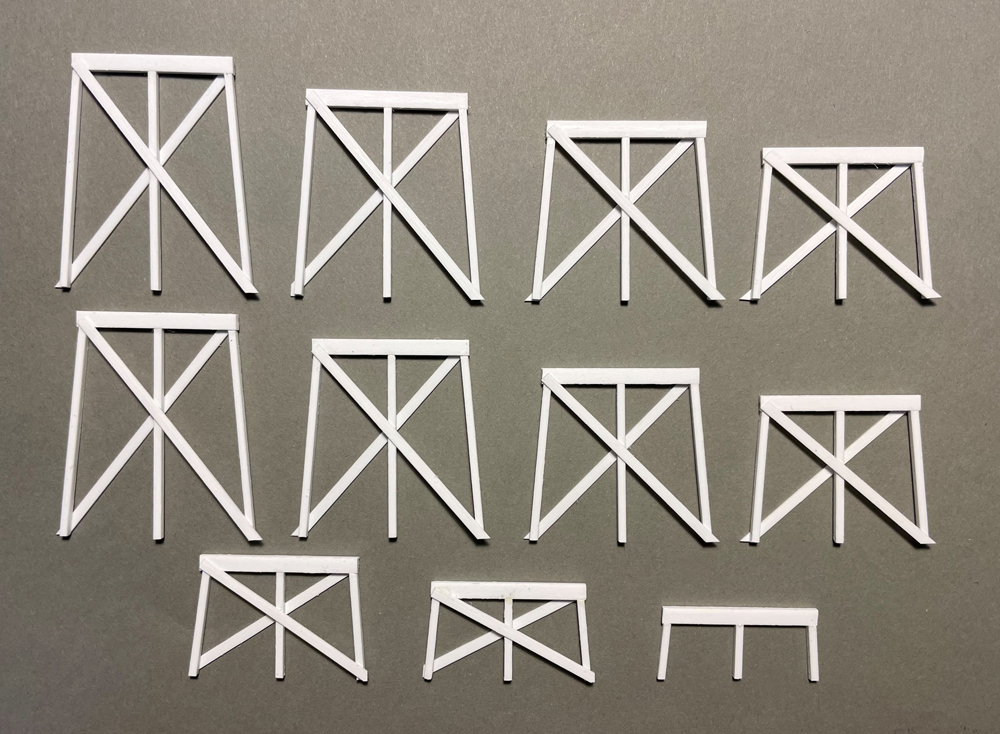
With the bent still in the jig, I added a .020″ x .080″ diagonal sway brace to those taller than 5 scale feet. After a minute, I removed the bent from the jig and added the brace on the other side. The finished bents are shown above.
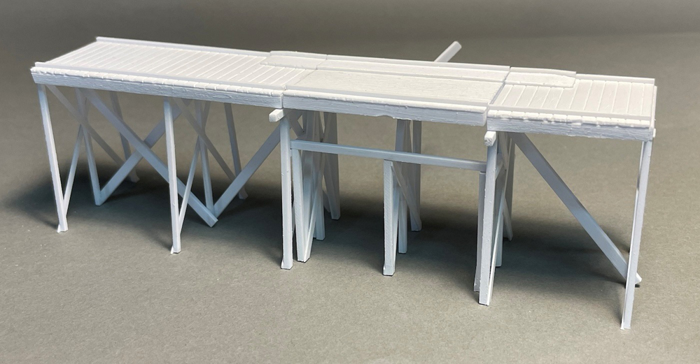
Main deck assembly
Turning again to the techniques I used to texture the tilt platform decking, I prepared enough .040″ thick .125″ spacing V-groove sheet for the decking on the entire model. I cut 10 scale foot wide decking to length for the two-level sections on the descent side of ABCDE assembly and one section on the approach side.
I also readied lengths of .060″ x .125″ strip for the stringers, sanding for texture and slightly rounding edges with a knife blade. I cut the stringers to length and cemented them to the decking.
Next, I glued the three tallest F bents to the decking and stringers, adding a .060″-square strip to strengthen the joints between the bents and bottom surface of the decking. The bents that will connect to the ramps have their caps exposed from beneath the decking.
Then I attached the assembled decking and F bents to the ABCDE assembly, also using .060″ square strips to strengthen joints, and checked that everything was square and level before the joints hardened. Finally, I glued four .060″ x .125″ center braces diagonally between center posts to the left and right of the ABCDE assembly.
The rising side of the tilt platform deck has an extra scale 4″ of decking to encourage tipping, with adjacent ramps to ease one wagon side up onto it. I cut this from .040″ thick .060″ spacing V-groove sheet six boards wide and the length of the tilt platform. I textured as I did for other decking and cemented it 1 scale foot from the rising edge of the tilting platform. See drawing 3.
I also cut and sanded wedge-shaped ramps six boards wide by 5 scale feet long for the approach and descent sides adjacent to the tilting platform. I cemented the ramps in line with the raised decking on the platform.
Finally, I attached .040″ square strips 1 scale foot in from both edges of the decking the entire length of the assembly and the tilt platform. This was right along the outside edge of the raised decking of the platform.
Main deck railing
Following the main drawing, I cut .040″ square and .020″ x .040″ railing posts 4 scale feet long. I cemented the square posts at the bent center lines, flush with bottom of the deck stringers, ensuring they were vertical. I glued the .020″ x .040″ posts at the midpoint between the square posts. Note that one mid-span post on the back side is a .040″ square post.
I started the railings by cementing the .020″ x .080″ bottom rails to the posts. Next came the .020″ x .040″ cap rails across tops of posts. Finally, I attached the top rails flush with top of cap rail and finished with the mid rail eye-balled between top and bottom rails.
Pulley frame
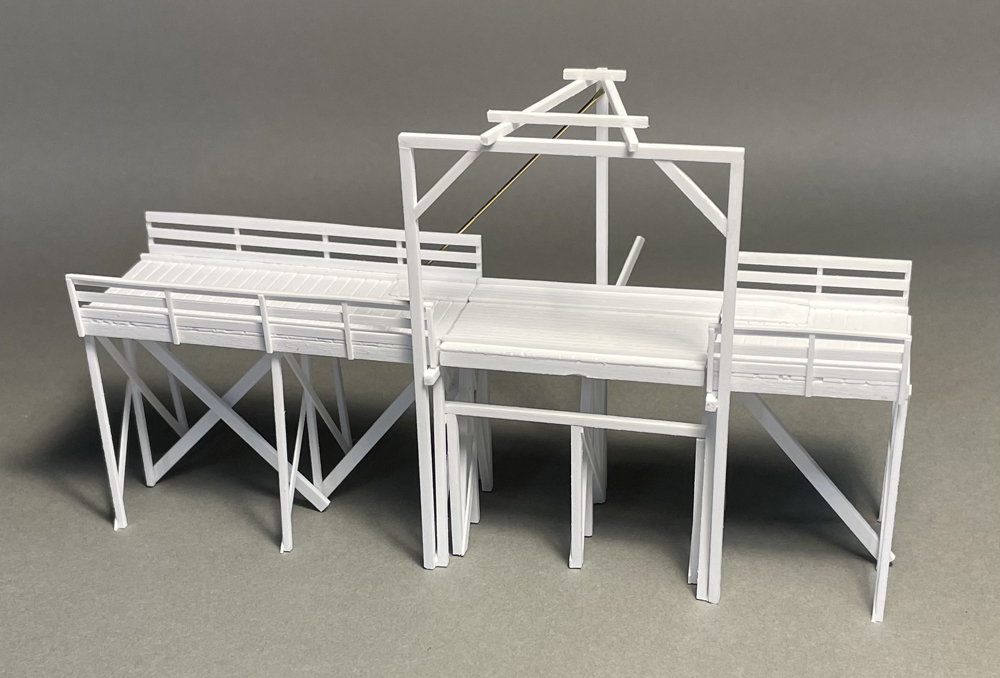
I started the pulley frame by cementing the front together on the main drawing, first the .080″ square posts and beam, then the corner braces. I then aligned and squared the pulley frame front with the main deck assembly and attached it to the AE bent cap extensions, the bottoms of the AE bent bracing, and the railing.
I cut and glued the .060″ square rear beam to ends of AE bent caps below the deck stringers, then cemented the rear Pulley Frame post to midpoint of rear beam, ensuring it was vertical. I cut and attached the two .060″ square V-rafters across the front beam and the top of the rear post.
The prototype had a diagonal brace, which I cut from a 1/32″-diameter brass rod 2 ½” long. I flattened 1/8″ of each end with a hammer, then attached it between the bottom of .040″ square mid-span railing post and the top inside of the rear post with cyanoacrylate adhesive (CA).
I cut the two .060″ square cross-rafters and drilled a No. 74 hole through the center of each for the Grizzly pulleys. I cemented the cross-rafters across the V-rafters.
Operator platform
I built the two sides of the operator platform directly on the drawing from .060″ square posts and .020″ x .060″ braces. See drawing 4. The approach side has three posts, while the descent side only two posts – its third post is the rear .080″ square post of the pulley frame. Note the inside vs. outside attachment of the sway braces.
The platform deck is .040″ thick .125″ spacing V-groove sheet 12 scale feet long and 6 planks wide. I cemented it between the sides, aligning the front edge with the front edge of the approach side. The rear deck edge extends just beyond the rear posts. I held everything square and level while it cured. I had to add a .020″ x .060″ strip under the approach side to level the platform. This also made the model stronger.
I cemented the cross braces between the sides, the joists beneath the deck, the rails and cap board for the approach side, and finished with the rails between the rear posts – all with .020″ x .060″ styrene strip.
With the free-standing work complete, I fit the platform to the rear of the main deck, using the rear pulley frame post as the third post on the descent side, and cemented the platform in place. I glued the rails and cap board to the descent side and the pulley frame post. I added a short scrap of .020″ x .060″ strip on the back side of the pulley frame post to support the cap board.
I finished by cementing the final joist beneath the deck between the pulley frame post and approach side post.
Dust apron
Using the main drawing, I cut the dust apron flooring from .040″ thick .060″ spacing V-groove sheet per the drawing. The flooring shape is complex and not simply 4-sided.
I cut and glued the .040″ square top rail flush to the top edge of the flooring, followed by the three vertical uprights. I then cut and cemented the bottom .040″ x .060″ centered and flush to the bottom of the flooring.
By trial and error I cut and fit the two diagonal .040″ square braces flush to their flooring edges. I did the same with the .020″ x .040″ horizontal brace in four pieces.
I cut the .040″ x .080″ dust beam to length, then cemented it centered and flush to the bottom of the dust apron. Then I cut four scale foot long hinges from .010″ x .060″ styrene, and glued a .010″ x .020″ strip across the center of each as a hinge pin. I attached the four hinges between the bottom of the dust apron and the dust beam.
I cemented the dust beam to the front of the pulley frame posts, with the bottom of the beam 5½ scale feet above grade. I didn’t glue the top of the dust apron, but shimmed the top of the dust apron away from the posts with scrap .040″ styrene while the dust beam dried.
Ramps
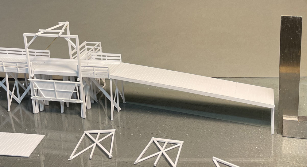
Next, I cut the previously prepared 10-scale-foot wide decking to length for the four wooden sections of approach ramp and the eight sections of descent ramp. I made stringers to match, cutting at a slight angle per the main drawing over the bent that starts the slope of each ramp. I cemented the stringers to the decking, pressing the assembly flat while it cured to prevent warping.
I fit the high end of the approach ramp to the main deck. I adjusted stringers and decking as necessary for a tight fit. The ramp deck fits over the exposed bent cap at the end of the main deck.
I cemented the short F bent to the end of the approach ramp, adding a .060″ square styrene strip to strengthen joint between bent and deck bottom. As it cured, I aligned the bent vertically.
With the ramp in place, I glued the remaining F bents to the approach ramp decking at 12 scale foot intervals, adding square strips for strength and ensuring they were square across the deck and vertical.
I finished by attaching the .040″ square wheel guide strips 1 scale foot from the edges of the deck for the length of the ramp. I then built the descent ramp in the same way.
To add ramp railings, I followed the steps for the main deck railings. Note that the rails are narrower, just .060″ wide.
I left the ramps unattached to the main deck until final assembly.
Painting and details
With the structure assembled, I turned to my go-to method for weathered wood. I was after a maintained but in-need-of-paint look.
I’d brush-painted the now-buried ABCDE assembly earlier, so now I brush-painted the rest of the three structures White as well.
When dry, I finished with light, sloppy washes of Black Gray, and then Burnt Umber (both from the Vallejo Model Color line). I like to streak and dab for variation, and I checked results under layout lighting between coats. Less is more.
When I was satisfied, I painted five nut-bolt-washer (n.b.w.) castings Burnt Umber. I cemented four at the ends of the pulley frame to AE bent extension bolts and one at the center of the dust apron.
Making brass pulleys
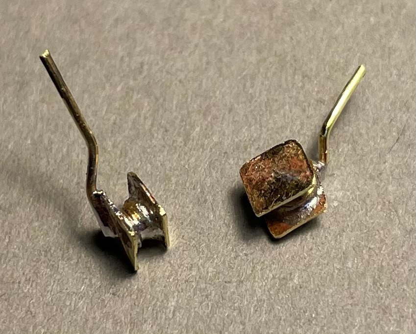
The rope that animates the Grizzly travels over two brass pulleys for low friction and strength.
To make each pulley, I clamped a 3/32″-diameter brass rod in a drill chuck and cut a wheel groove with a hobby knife as the drill slowly spun.
Then I cut two 1/8″ squares from .010″ brass sheet. Taping one square to scrap plywood, I applied flux and soldered a wheel to its center. I aligned the second square with the first, then soldered it to the wheel.
Finally, I bent a 2″ length of .020″-diameter brass rod, then soldered it from center of one square to a corner and out.
I spray-painted both pulleys with gray primer, then applied washes of Burnt Umber and Black Gray. I used CA to attach a pulley into each hole in the pulley frame cross-rafters, aligning them for the Grizzly rope.
Details make the model
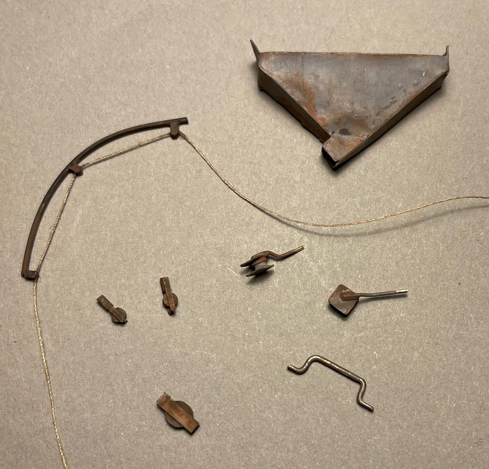
I scratchbuilt the details shown above. Here are the specifics on each.
Dust bucket boom: I bent a length of 1/32″-diameter brass rod around a pill bottle to match the radius of the boom and cut it to length per the main drawing. I made three pulleys by drilling a No. 74 hole in .040″ square styrene strip and cutting to size for a pulley. I filed a triangular groove in one end of each and sanded a round profile at the other. I drew a length of rope color sewing thread across beeswax to prevent fuzzing, and threaded the three pulleys onto it (I used beeswax on all of the rope for this project.) I glued each pulley to a position on the bottom of the brass rod per the drawing with CA.
Leaving 20 scale feet of rope on each side of the boom, I attached the rope in place on one end pulley, pulled taut, and glued the rope to other end pulley. I painted the brass and styrene Burnt Umber, avoiding the thread.
I cut a .080″ x .160″ strip of paper, bent it in half, and attached it with CA to the corner of pulley frame post as the hinge for the boom. I carefully painted the hinge with Burnt Umber and Black Gray. I glued the boom to the paper hinge, and draped the rope for effect. I used CA to attach guy and tether ropes between the boom and the pulley frame.
Dust bin: I cut the dust bin Cut-N-Fold from the drawing, folded and used a dab of white glue on tabs to assemble it. When dry, I applied a thin coat of full-strength yellow glue for a waterproof seal. I sprayed the bin with gray primer, then weathered it with a Burnt Umber acrylic wash.
I used CA to attach the bin between the front post of the C bent and the dust apron beam, ensuring the bin front edge was flush with the beam top and centered on the bent.
Wagon chain and slide bar: I bent a 1/32″-diameter brass rod into a slide bar 6 scale inches high and 2 scale feet long with 6 scale inch long attachment “wings.” I flattened the wings and painted with Burnt Umber.
I glued the bar centered just inside the rising edge of the tilt platform deck with CA. I attached one end of 6 scale feet of chain to a random spot on the slide bar with CA, leaving the rest of it loose.
Dust apron rope and pulley: I cut a pulley disk from a round styrene sprue about .140″ diameter and sanded to .060″ thick. I cut two ¼” lengths of .010″ x .060″ styrene strip and cemented to opposite sides of the disk, aligned with each other and extending equally beyond the disk edge. I glued a .040″ square styrene strip between the side strips at one end, leaving room for the rope, and painted it all Burnt Umber.
I brushed full strength matte medium on my rope thread to give the rope shape. I glued the rope to the back of the dust apron behind the cross and n.b.w. casting. I threaded the pulley onto the rope and cemented the .040″ square strip end of the pulley bracket up against the stop beam. I pulled the rope taut and glued it to the top of the pulley disk with CA, then pulled taut again and glued the rope to the front post of the C bent about 4 scale feet above grade, leaving another 8 scale feet of thread to drape as desired.
Wagon release rope and pulleys: I sliced two pulley disks from round styrene sprue about .080″-diameter I cut four ¼” lengths of .010″ x .030″ styrene strip and cemented them to opposite sides of the disk, aligned with each other and extending equally beyond the disk edge. I cemented a .040″ square strip between the side strips at one end of each pulley, leaving room for the rope. I painted everything Burnt Umber.
I glued one small pulley beside each Grizzly pulley on the pulley frame, and attached rope from the operator platform through the pulleys and down to one of the pulley frame front posts with CA, about 4 scale feet from the deck, keeping all taut.
Rope on platform beam: I tied and glued a 12 scale foot length of rope to the end of the tilt platform beam, draping the rope for effect.
Building the Grizzly
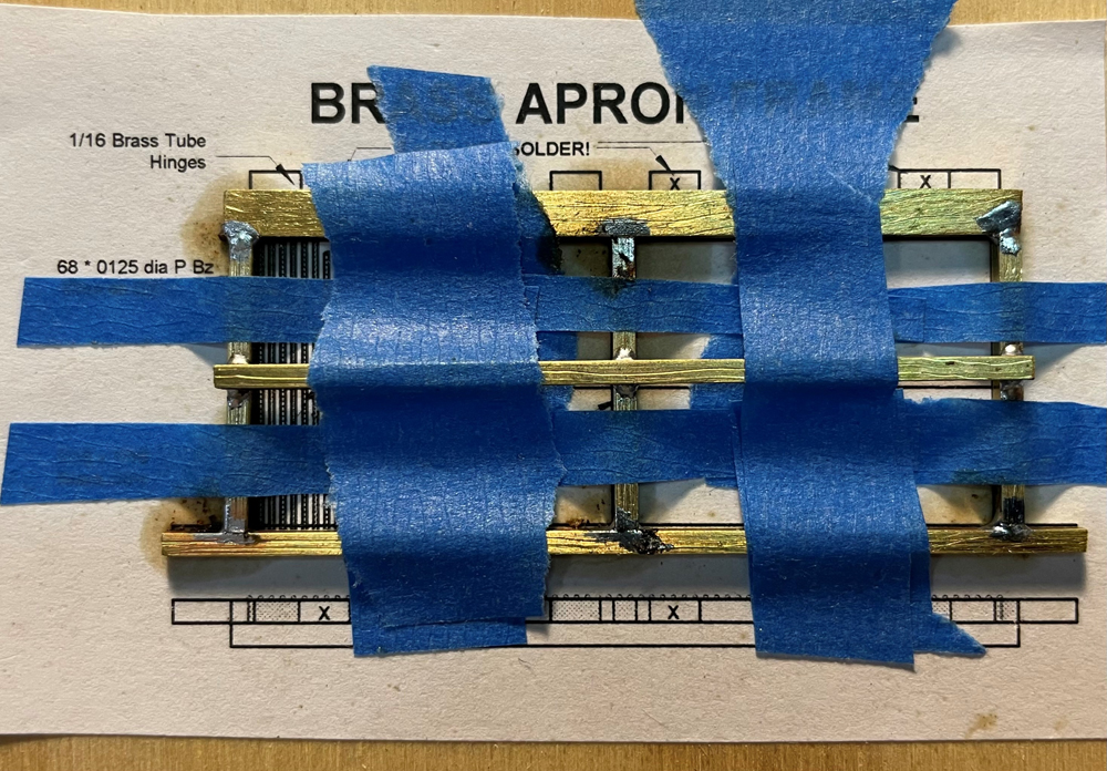
To keep its rope taut, I built the Grizzly and its hinge beam from brass for the weight. I cut 1/8″ wide and 1/16″ wide brass strips from 1/16″ x ¼” brass stock.
After cleanup with a file, I sanded the strips with 60-grit sandpaper for texture, and scribed wood grain with a razor saw blade dragged at a right angle to the surface. I really bore down on the blade to get grain to show up.
I cut the six pieces of 1/16″ square and 1/16″ x 1/8″ brass as in the main drawing. I attached the Grizzly assembly drawing to a scrap of plywood with white glue, taped the brass down, added flux as necessary, and soldered the pieces. I cut six 12-scale-inch lengths of 1/16″-diameter brass tube for the hinge. I slid these short tubes onto a 1/32″-diameter brass rod, and aligning three tubes with the unmarked tubes in the drawing, I soldered them to the top edge of the Grizzly frame.
I cut the hinge beam to fit easily between the pulley frame posts when resting on the AE bent beam extensions. After taping the hinge beam to the drawing, I aligned the remaining three tubes on the brass rod with the X-marked tubes, and soldered them to the hinge beam.
I cleaned everything with jeweler’s files and a wash with detergent and water, then checked that the hinge worked properly.
Adding the Grizzly bars
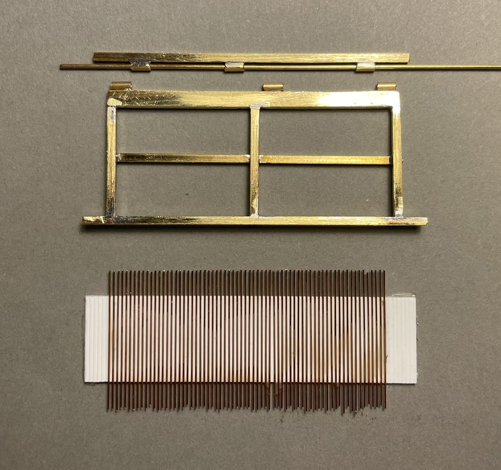
The Grizzly bars were made from pipe on the prototype. To model them, I cut 68 1″ lengths of .0125″-diameter phosphor bronze wire with a hobby knife. I arranged the wires into the grooves of a 5/8″-wide piece of .040″ thick .030″ spacing V-groove styrene sheet, aligning one side with a straight edge. After wetting with isopropyl alcohol, I flowed on diluted white glue to adhere the wires to the styrene.
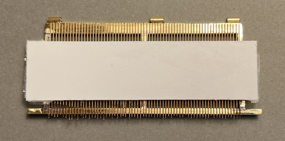
After drying overnight, I turned the styrene over and positioned the aligned edge of wires with the top edge of the frame. With the wires straight with the sides of the frame, I used CA to attach the wire to the frame.
I touched up any loose wire ends with CA, then soaked the Grizzly in water to release the bars from the styrene. I finished by trimming the bars flush with the bottom of the frame.
I spray-painted the Grizzly and hinge beam with gray primer, then added washes of Burnt Umber and Black Gray. I drybrushed more Burnt Umber on the bars.
Animating the Grizzly
I cut a hinge rod from 1/32″-diameter brass and painted it Burnt Umber. I threaded the rod through the hinge tubes to assemble the Grizzly and hinge beam. I put a drop of CA glue at each rod end to hold it in place. I attached the hinge beam onto the compound bent extensions with CA, aligned with the pulley frame posts.
I also used CA to attach one end of a length of rope to the Grizzly rope stud, then threaded the rope over the heavy-duty brass pulleys and down to the backside of the structure. Pulling on the rope, I tested for smooth movement of the Grizzly.
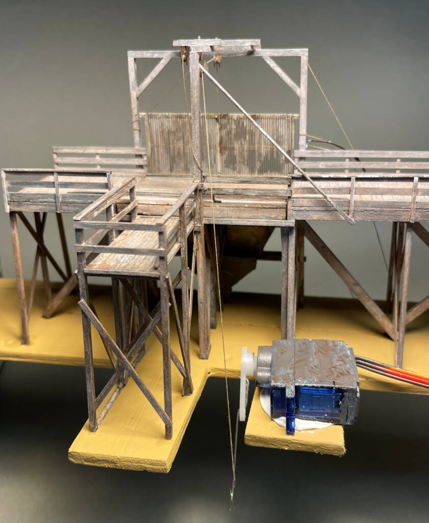
I built a base for the entire model from two wooden yardsticks. I used yellow glue to attach the pieces edge to edge to form a 2″-wide base, and cut and glued yardstick pieces as extensions to support the operator platform and servo. I placed the flat, under a weight, while the glue dried. I finished by painting with my base scenery color.
After determining base and structure alignment with my track, I glued the main deck to the base with CA. I extended the servo arm to a 10 scale foot radius with .025″-diameter music wire for plenty of pulling distance. Positioning the servo to best operate the rope, I then glued the servo to the base with acrylic caulk. I taped the rope to arm, connected the servo to its controller, and followed the controller instructions to finish setup of the servo. After testing to my satisfaction, I glued the rope to the servo arm with CA.
Finally, I used CA to attach the chains in place with the Grizzly in its down position. I also built guide boards with 18 scale inch long .010″ x .060″ stakes and 7 scale foot long .020″ x .125″ boards, which I weathered and glued into place.
Finishing touches
I cemented the ramps to the ends of the main deck and glued them to the base with CA. I built two “dirt sections” of the descent ramp from Sculptamold, painted them my base color, and sifted on dirt while wet. I brushed full strength matte medium onto the base around and between the bents and sifted on dirt while wet.
I cut a hole in my sub-roadbed for the long throw of servo arm and finished the scenery behind and around the beet dump site. I slipped the finished beet dump and its base into place and connected the servo to its controller. I finished the scene with farm wagons from Berkshire Valley Models and horses from Knuckleduster Miniatures.
The Niwot beet dump is now open for business. Even if you don’t need to build a beet dump for your layout, I hope you can put some of these tips and techniques to use on your next scratchbuilding project.
Jim Ferenc lives in Boulder, Colo., where he models the Colorado & Southern in HO scale. His article “Animate a coal mine” appeared in the June 2023 issue of Model Railroader.
Materials list
41821C Sculptamold
Campbell Scale Models
256 black chain, 42 links per inch
Evergreen Scale Models styrene (strip unless noted)
100 .010” x .020”
101 .010” x .030”
103 .010” x .060”
122 .020” x .040”
123 .020” x .060”
124 .020” x .080”
125 .020” x .100”
126 .020” x .125”
142 .040” x .040”
143 .040” x .060”
144 .040” x .080”
146 .040” x .125”
153 .060” x .060”
156 .060” x .125”
164 .080” x .080”
166 .080” x .125”
4030 .040” V-groove sheet (.030” spacing)
4060 .040” V-groove sheet (.060” spacing)
4125 .040” V-groove sheet (.125” spacing)
K&S Precision Metals (brass unless noted)
5005 .025”-diameter steel wire
8125 1/16”-diameter tube
8159 .020”-diameter rod
8160 1/32”-diameter rod
8162 1/16”-diameter rod
8163 3/32”-diameter rod
8245 1/16” x ¼” strip
16402 .010” sheet
5582 ColorMaxx gray primer
OSCAL33P O scale 3 x 3 (1/16” square) stripwood
5046 1-3/4” square nut-bolt-washer casting
SRV002 Servo motor
Mark III servo decoder
1106 .0125” phosphor bronze wire
Vallejo Model Color acrylic paint
70.862 Black Gray
70.941 Burnt Umber
70.951 White
Miscellaneous
Sewing thread
Yard stick


Two things…
First – fantastic model work!
Last – There’s a really bad poop joke in there, but I don’t think I should….