


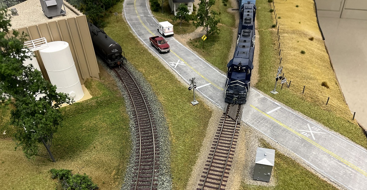
From tabletop, to shelf, to open grid, there are a lot of different methods you can use to build model railroad benchwork. For our HO scale East Troy Industrial Park project layout, we used a combination of two methods, cookie cutter and L-girder, to make solid, stable benchwork.
While not exactly framing for a layout, the cookie-cutter method is a simple way to add subroadbed with elevation to a model railroad, particularly if you still need a lot of relatively flat spaces for things like large industries, which was our case. Rest assured; we’ll cover this technique of using plywood and risers in greater detail in the next installment of this series. For now, know that the best part about cookie-cutter elevation is that you can use it in combination with a number of layout support systems. To support our East Troy project, we chose L-girders.
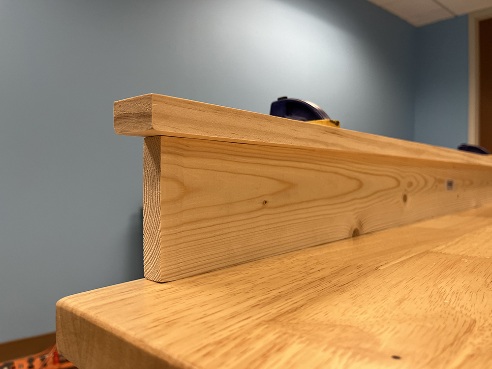
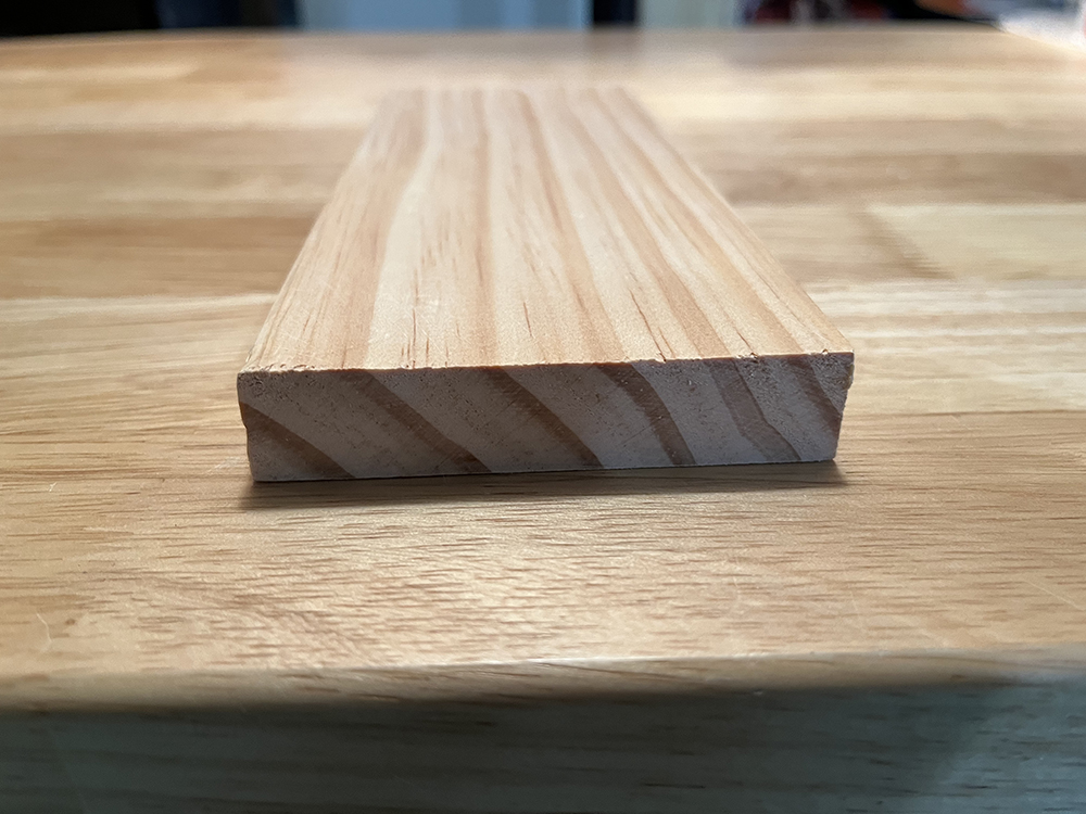
Created by former Model Railroader editor Linn Westcott in the 1960s, L-girder benchwork uses pairs of simple L-shaped components as its foundation. As shown in the photo below, an L-girder is constructed from a beam made from a 1 x 3 or 1 x 4 board and topped with a flange, typically made from a 1 x 2. By attaching the flange to the top of the beam using wood glue and either nails or screws, it creates a stable girder capable of holding significant weight and spanning distances of up to 12 feet without support. You can then build just about anything you wish on top of that framework.
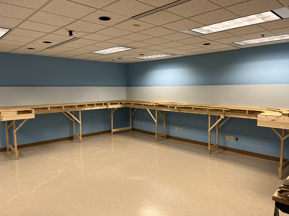
Our L-shaped layout runs 14 feet in one direction and 19 feet in the other, which makes it ideal for using L-girders to support it with a limited number of legs.
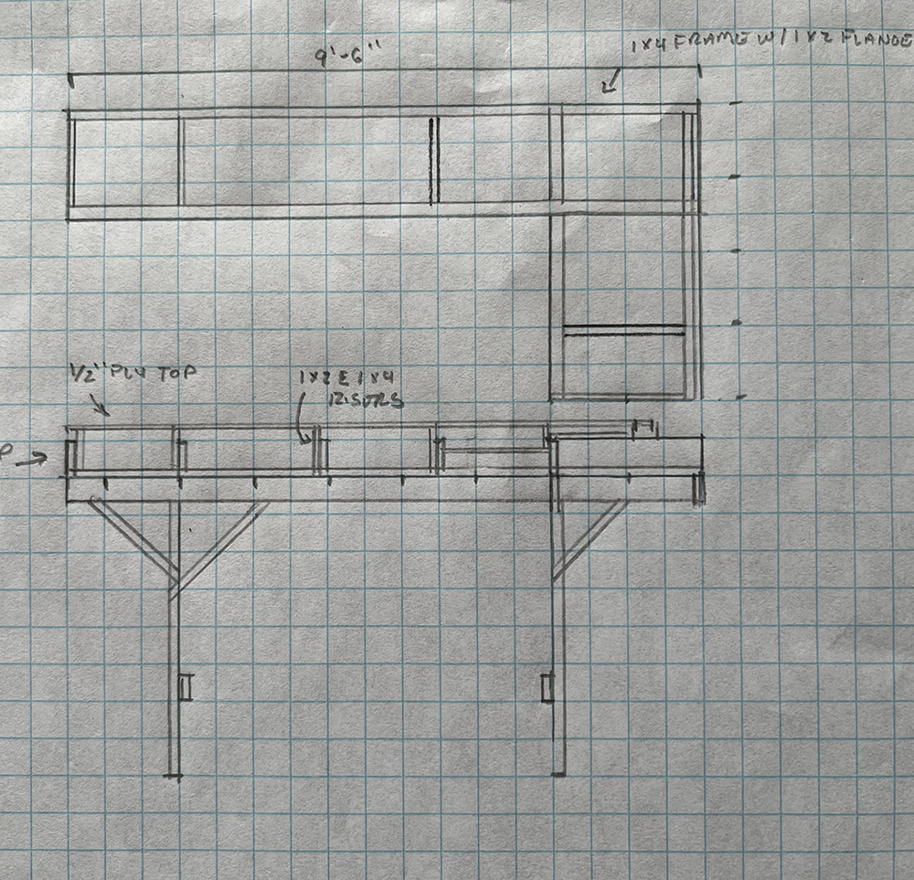
Framing sketch
Although I’d created the track plan for the layout much earlier, it wasn’t until we decided to build that plan that I then drew up a framing sketch for it. Not only did this document serve as a construction guide, but it also allowed us to figure out how the sections of the layout would fit together.
On the former Milwaukee, Racine & Troy HO layout, we used L-girder construction extensively. Unfortunately, that layout was built in such a way that it was impossible to disassemble to move it. Since we were going to build East Troy in our video workshop, it would eventually have to move elsewhere in our building so that we could use the space for other projects. Therefore, unlike the MR&T, we planned to make East Troy a portable layout from the beginning.
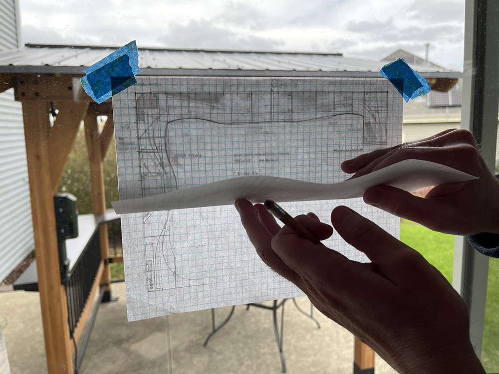
To draw the framing sketch, I started by tracing the footprint of the track plan on a new sheet of graph paper. I’d drawn the original plan at ½” = 1’-0”, so I did the same here. While a light box makes tracing a plan easy, most people don’t have one, including me. My solution was to tape the plan to my sliding patio door on a sunny day. I then taped a clean sheet of graph paper over it, lining up the grid to the plan beneath it. Thanks to the sunlight, I could see the track plan well enough through the top sheet of paper to trace its outline with my pencil and straight edge.
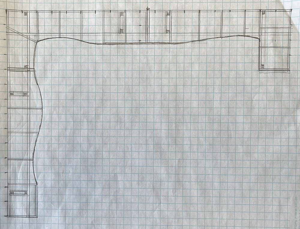
Knowing that we would split the layout into three nearly identical sized pieces, I drew the support structure onto the layout’s traced footprint. I used this sketching process to get an idea as to how the L-girders and spacers would need to be placed to build each section. In addition, I marked the potential location for the layout’s legs. Each section has 4 legs arranged in pairs so that the individual sections are self-supporting. I also included a rough idea of where the fascia might go. I say might, because during construction, the front of the layout and its fascia arrangement changed quite a bit.
You’ll probably note that by comparing the early drawings shown here to the finished layout, this is not exactly how the railroad turned out. We ended up making a number of changes during construction, including widening much of East Troy to 30” and adding a 24” x 24” bump to the end of its section. This allowed us to curve the end of the main line for a potential future addition. Although not a complete plan for building the layout, the early sketch served as a useful starting point for the next step in the framing process.
Frame and leg blueprint
With a rough idea for the framing plan down on paper, I next created a detailed design for one of the layout’s 9’-6” sections. In the detail drawing, I included the L-girders and their cross members used to make self-contained frames. I also drew a profile sketch for the section, showing the elevation of the layout and included the legs, bracing components, and a rough estimation for the position for the joists.
All three layout sections are intentionally L-shaped with a 4-foot end and 24” to 30” cross section on the long side. I designed them this way to keep the bulk of the curved trackwork contained within its own section. (Curves are more difficult to align properly on portable layouts than straight sections.) Each are nearly identical in construction, except the Mukwonago section’s 4-foot L piece faces opposite the other two. Also, based upon available room space, the East Troy section is 6” longer, totaling 10 feet.
Estimating lumber
The sketches not only provide a blueprint for construction, they also are a great aid in estimating the number and lengths of the boards required to build the layout. With my design in hand, I used my scale ruler to measure the components and estimate the number and sizes of the boards required to build the layout.
If you’ve never done this before, it’s actually kind of fun. For example, each pair of 40” legs on the layout uses a single 8-foot 2 x 2, half of an 8-foot 1 x 2 to make two 24” angle braces and 24”-36” worth of an 8-foot 1 x 4 for the bottom spacer. The remaining material not used in that pair of legs can then be assigned to another pair or some other part of the layout. I keep a tally sheet handy as I work through the plan. Since we were going to build three sections, I took my estimate for one section and tripled it.
You will make changes during construction, so it’s best to always figure one or two more of your commonly used boards into your estimate, such as 1 x 2s and 1 x 4s. You will inevitably need to go back to the store for a few more at some point, but this will give you a good head start in the construction phase.
When choosing lumber for your layout, be selective and take your time. You want boards that are straight and sound, without splits or excessive knots. Also watch for cupping, the curving of a board along its grain. It’s fine if some of the boards cup slightly, but excessive cupping can make a board difficult to attach flush to the benchwork. To test a board for cupping lay it on a flat surface or place a straight edge across its end to see if it lays flat or curves.
Lumber quality is one place you don’t want to compromise when building your layout.
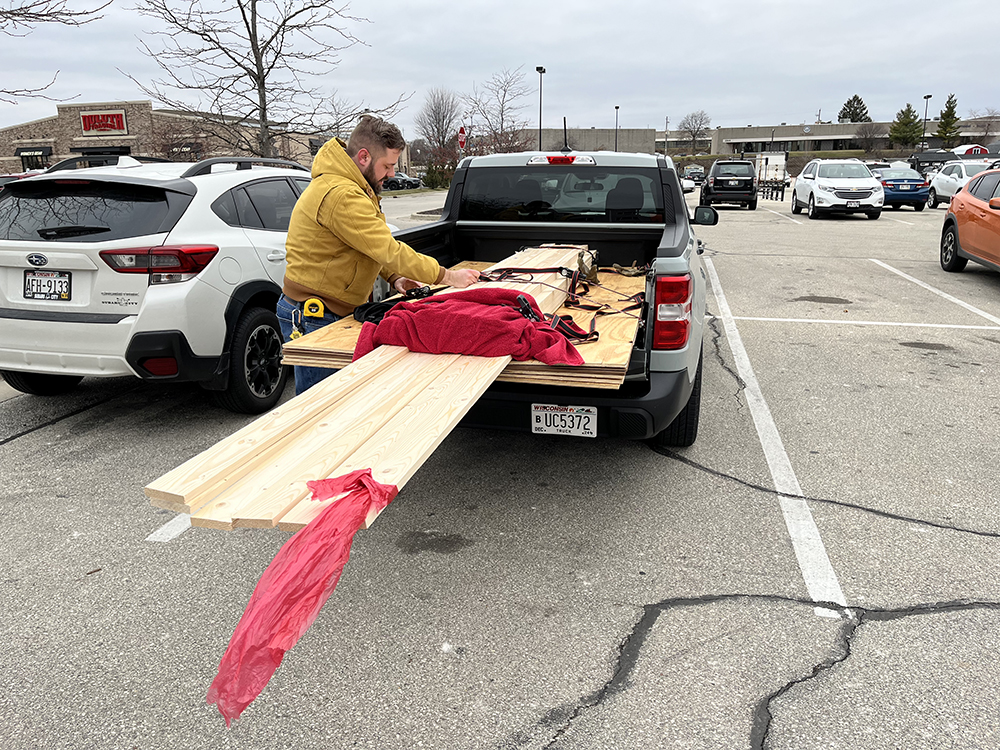
Don’t be afraid to be picky. Lumber costs a lot to begin with, and the quality of the boards makes a big difference in how easily a layout goes together, as well as how well it holds up over time. When Bryson and I purchased the boards for the East Troy layout, we couldn’t get everything we needed from just one store. We got good 12-foot 1 x 4s from one place, but they didn’t have any straight 2 x 2s that we needed for the legs. We found those at a different store across town.
Most new lumber still has a lot of moisture in it, so although it looks straight when you buy it, it could warp as it continues to dry out. When you get the lumber home, if possible, store it in the layout room so it can adjust to its new location. Also, don’t lean it against a wall or it will assume a very nice curve all on its own thanks to gravity. Instead, lay it flat, and it doesn’t hurt to clamp the boards together if it will be a while before you can begin construction. By locking the boards together this way, they keep each other straight and true as they continue to dry.
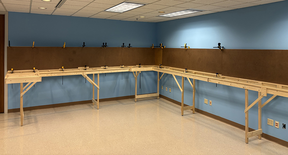
Building at last
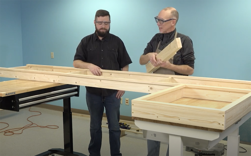
Bryson and I started construction on the Mukwonago (far right) end of the layout, building the L-girder frames for one section before moving on to the next one. The first components were the long L-girders. We cut the 1 x 4 beams to span the full length of the 9’-6” section, less ¾” on each end (1½” total) to accommodate the 1 x 4s used to form the ends of the frame. As shown in the photo, we cut the 1 x 2 flange pieces the full length so that they would overlap the frame’s end boards and make a solid corner joint.
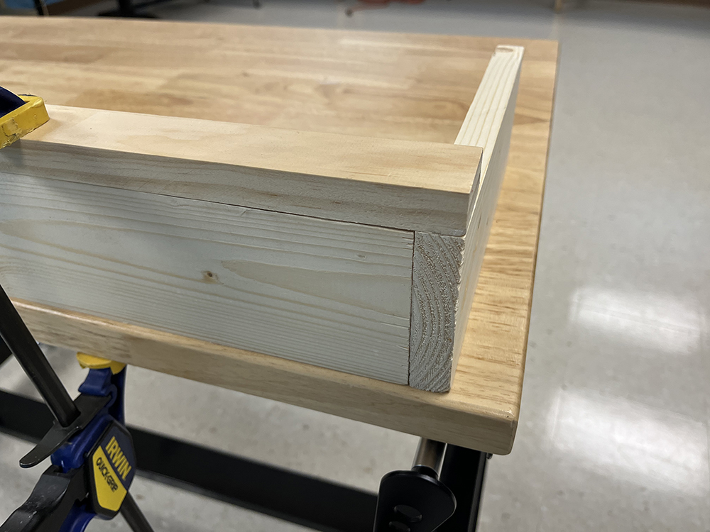
Once we had a pair of L girders made this way, we then cut the spacing boards for the long section and the 4-foot L-shaped end frame.
The 24” x 24” L at the end of each layout section is also made with L girders, which allowed us to put joists in just about any arrangement we needed to support the subroadbed at the corner. We laid the pieces for each frame section upside down on our two portable worktables to facilitate assembly.
Although I’ve built layouts straight on the shop floor before, I much prefer using worktables for this job. First, it puts the work up where you can see it, which also saves you the trouble of having to kneel on the floor for long periods of time. More importantly, however, is that you can clamp the frame’s pieces straight to the workbench top – something you can’t do when building it on the floor. This makes it far easier to get square corners and flush fitting joints, which ultimately leads to better benchwork.
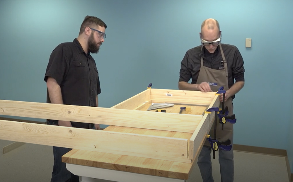
As mentioned earlier, try as you may to get straight lumber, you almost always end up with some pieces that warp or cup a bit. When assembling benchwork, always work with squares if you can, to make sure the pieces fit properly. Also ensure that the parts fit flush from top to bottom. If you do find you have a gap, you can usually pull it together with clamps or by having an assistant secure it by hand while you then drive screws into it to lock it in position.
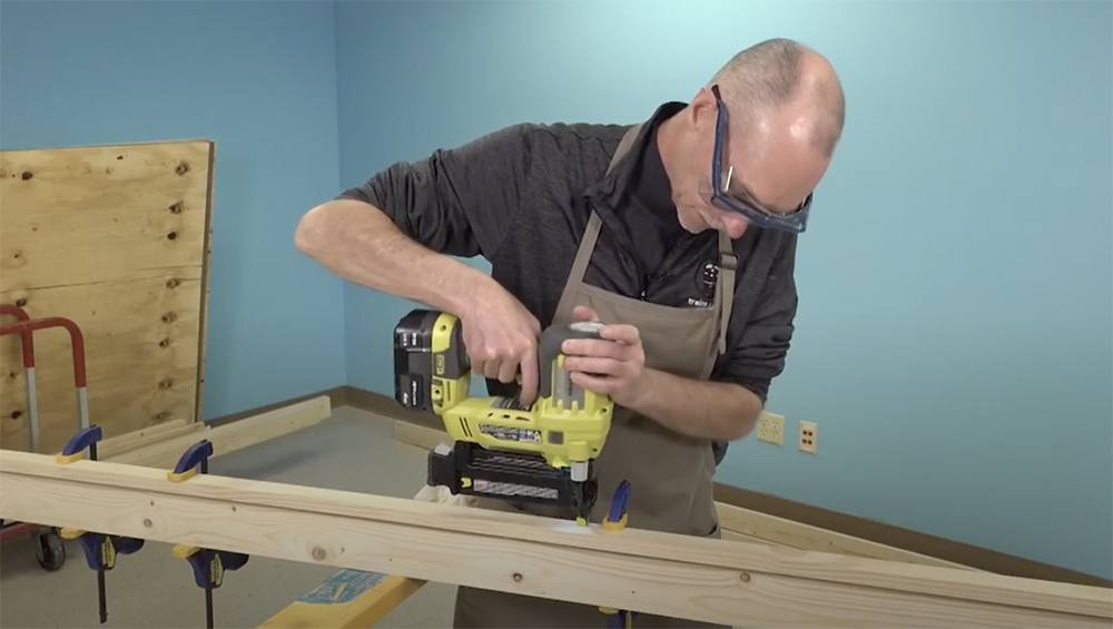
Unless we knew it would be a section that might have to come apart again, Bryson and I made all framing connections the same way, using wood glue and countersunk deck screws.
After test fitting the parts, we applied glue on the connecting edges and clamped the pieces to the workbench and to each other if at all possible. Next, we drilled a small pilot hole for the screw, using a drill bit that was slightly smaller than the width of the screw. Next, using the screw hole as a guide, we used a countersink bit to form a small cup in the wood that was just deep enough for the tapered head of the screw to sit flush with the surface of the wood. We then installed the screw, using a driver bit in the drill.
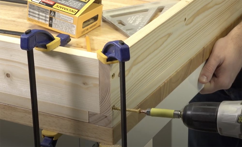
Be careful not to drive the screw too deeply, or you can split the wood – particularly if the screw is placed close to the end of the board. It also helps to have more than one drill available for this operation. Bryson and I used two drills, and we could have easily used a third, so as to be able to drill holes, countersink them, and drive the screws without constantly changing bits.
More Benchwork to come
It took Bryson and I a couple of days to build all L-girder frame sections. As we completed each one, we double checked the joints and corners to make sure nothing as moved out of alignment during assembly. We then set the completed frame aside and started the next one.
Working carefully to achieve straight joints and tight connections during construction goes a long way towards making all other steps of the benchwork project go smoothly. Speaking of other steps, adding the legs will be the next installment in our East Troy Industrial Railroad series.
Click here to read the previous installment of the East Troy Industrial Park series on Trains.com.
Click here to read the next installment of the East Troy Industrial Park series on Trains.com.
Interested in learning more about benchwork for your model railroad? Click here for “Basic Model Railroad Benchwork, 3rd Edition” on shop.trains.com!


Interesting that you built in one room to then move and install in another room.
Was it just space to work in or some other reason?