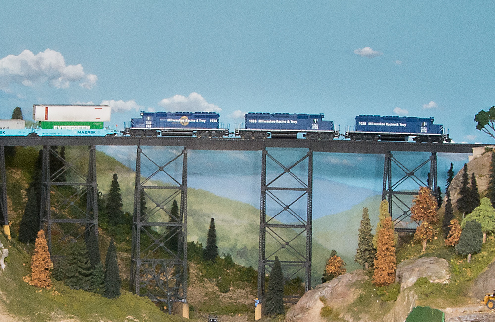
Five tips for trouble-free turnouts: Since turnouts play a prominent role on model railroads, they deserve attention before and after installation, as well as during routine maintenance. Taking the time to ensure turnouts perform well will guarantee more reliable, and therefore more enjoyable, operation. Though all commercial turnouts meet National Model Railroad Association (NMRA) standards, each company has its own manufacturing processes. I use Micro Engineering’s code 70 turnouts exclusively on The Hills Line, my HO scale layout depicting Iowa Interstate’s Hills Industrial Spur. While installing turnouts on my model railroad, I’ve developed a series of tips, tricks, and tweaks to make sure they perform as flawlessly as possible. These techniques can be used as-is or adapted for other turnouts.
1. To the point
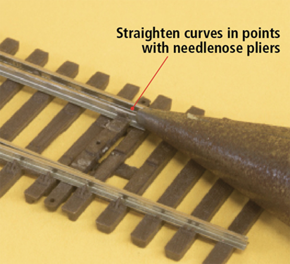
The points and frog are problem-prone areas on many turnouts. Points on commercial turnouts sometimes have a small curve or kink in them, preventing them from seating flush against the stock rail. When a locomotive or car passes through the turnout, the wheelsets may pick the edge of the point and derail. To remedy this, I use a pair of smooth-jaw needlenose pliers to smooth out any curve in the points. Do this carefully, as it’s easy to damage the delicate rail. I then take a flat jeweler’s file and gently swipe it along each point, forming a knife edge. This serves two purposes. First, it allows the points to seat flush against the stock rail. It also ensures that the wheels on locomotives and freight cars can navigate through the switch points without issue.
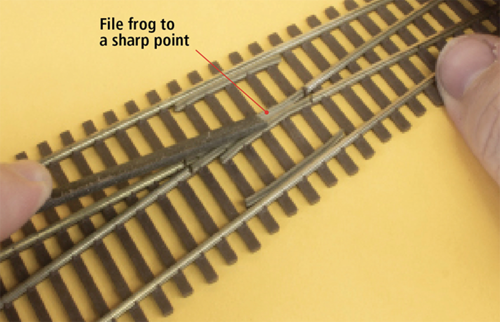
2. Fixing the frog
Frogs on commercial turnouts are often one-piece metal castings. As a result, they sometimes sit higher than the closure rails. The height difference, though sometimes subtle, is another possible cause of derailments. To bring the metal frog to the same height as the adjacent rails, I run the entire turnout over a fine-grit honing block, available at most hardware stores and home centers. The block is shown in the photo at left. The texture of the block is enough to shave down the frog but not damage the nickel silver rail. Once the cast-metal frog is level with the rails, I use jeweler’s files to remove any burrs from the guardrails and flangeways in the frog. I also use the files to shape the frog to a sharp point, as seen in the right-hand photo.
3. Electrical enhancements
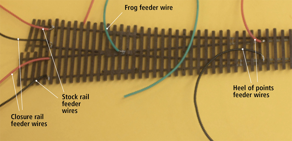
Today’s commercial track manufacturers have made great strides in making turnouts electrically reliable. However, I add a few extra wires to ensure there are no dead spots, especially since I run four-axle road switchers. I do all the wiring at the workbench before installing the turnout on the layout. The key to making turnouts electrically stable is to power the frog. While most locomotives can span the length of an unpowered frog, my smaller Electro-Motive Division GP38s will sometimes stall. To power the frog, I clean the bottom of the metal casting with a wire brush to remove oxidization or residue from the manufacturing process. Then I solder a length of stranded wire to the bare metal. The metal used in commercial frogs can make it difficult to attach wires. I make sure the tip of my soldering iron is clean and hot, and I use a fair amount of flux for a quick connection without melting the nearby plastic ties. I connect the frog feeder wire to a Tam Valley Frog Juicer once the turnout is installed. Turnout points generally receive their power from either a hinged connection to the closure rail or by making contact with the adjoining stock rail. Over time, and after painting, weathering, and ballasting, that connection can become intermittent or fail. I avoid that issue by soldering two 22AWG stranded feeders to the heel of the points. I double check that the points still move freely during and after I connect the feeders, and that no excess solder has flowed into the hinge. The remaining pieces of rail also receive feeder wires, including both routes out of the frog. I solder the feeders to the bottom of the rail base. Once the turnout is installed and the track is painted and ballasted, the wires are nearly impossible to see. Seven wires per turnout may seem overkill, but I’m guaranteed to have an electrically reliable turnout.
4. Special situations
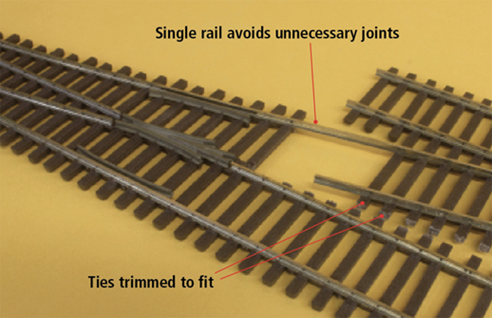
I also prepare complex track arrangements on my workbench before moving them to the layout. In some locations I’m able to shorten the length of the rails coming out of the frog, allowing me to lay turnouts in tight spaces. I use rail nippers to remove unneeded track beyond the frog and guardrails on the first turnout and before the points on the adjacent turnout. Then I connect the two turnouts. Micro Engineering’s new Yard Ladder System makes these steps above unnecessary. However, I feel it’s good to have options for making commercial track work in the space you have available. For crossovers (below), I lay two turnouts on top of each other with the tracks spaced 2″ apart. The unneeded inner rail can then be removed and the ties trimmed to fit. The opposite turnout rails can then be slid back into the remaining ties. This avoids unnecessary joints (and feeder wires) in the crossover. The same mechanical and electrical tweaks for single turnouts are applied to multi-turnout configurations.
5. Finishing touches
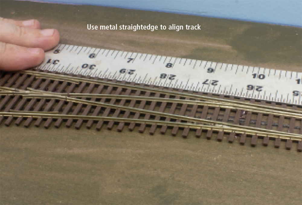
Finally, I install the completed turnouts on the layout and connect the feeder wires to the bus. Once in place, I double check to make sure the points still move freely and cleanly and that the turnout isn’t warped or bent. If I find a turnout that’s out of alignment, I gently press it against a metal straightedge to fix it, as shown in the photo below. Once I have the track aligned against the straightedge, I sight down the turnout and adjacent track to confirm it’s as straight as possible. Using commercial turnouts allowed me to get The Hills Line up and running in a short amount of time. Taking time to ensure the turnouts were mechanically and electrically optimized, however, means my layout will run smoothly now and in the future.