


In the July 2005 issue of Classic Toy Trains, I wrote a story about adding MTH’s Digital Command System to medium- and large-sized layouts. Here are some other tips and tricks I learned when planning and physically installing wiring for DCS on my 19- by 19-foot O gauge layout.
 First, you should design your wiring system before you even think about cutting the first piece of benchwork. When organizing and planning my layout, I used RR-Track track-planning software from R&S Enterprises, which allowed me to break my track plan into several layers. I created layers for the track, trackside accessories, operating accessories, and the DCS wiring and the electrical power blocks associated with it.
I also made layers for my track switches showing how I grouped them together for the MTH Accessory Interface Unit (the AIU operates both track switches and accessories), for my track buttons, and I finished things off with layers for all of my accessories and related wiring.
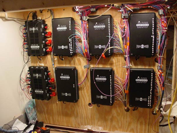
As you can see by the photo of my multiple TIUs and AIUs, it looks like an overwhelming task that could easily scare someone away. However, this system is actually very easy to wire. I did it through simple grouping and getting organized before construction began.
KEEPING THINGS ORGANIZED
I use several methods to keep everything organized. I suggest you first make a master plan, make several copies of it, and take notes – you will need those notes before you’re done.
I had two years to plan my layout when my house was being built and my basement finished. I was able to use the RR-Tracks software to lay out all of the layers of my layout. I had everything pre-numbered and was starting to get a gut feel for how much wire I would need for this layout before I built the first piece of benchwork.
Knowing the volume of wire going into it, I actually decided to build my benchwork from 2-by-4s. I then simply bored holes for the wiring through the horizontal 2-by-4 sections before any surface pieces were installed. I underestimated the amount of wire I needed to install and actually went back later and bored additional holes to handle the additional wiring.
Originally I had planned on building a main master control panel to run my layout, but I wound up scuttling the panel and today I run my entire layout – trains, track switches, and accessories – from my DCS controller.
One of the most important things when creating a DCS layout is to identify all your wires. There are several ways to organize and bundle your wiring.
A very affordable option is to use number tags on your wires, as professional electricians do. One of the mistakes I made with this was that I tended to repeat numbers. I can’t stress enough the importance of not reusing numbers. Number books are available from 0-100 at electrical hardware houses. You can get additional numbers if your layout warrants it, but I have approximately four miles of wire underneath my layout and I have yet to finish one number book. Number books cost about $7 and they will save you a tremendous amount of time.
Accidents do happen and tags come off, and the next thing you know you have massive confusion. To avoid this, make sure to tag both ends. I always use a minimum of two number tags at each end of a cable.
Color coding is also highly effective in organizing and keeping track of your wiring. Make sure to use color schemes that you can easily remember. I am a Master Electrician, so I tend to group and generate typical wiring diagrams based on the National Electric Code’s color standards. I use the high voltage color scheme of BOY (Brown/Orange/Yellow) for my accessory tracks. On some of my larger accessories, I used the phone-color standards, which use color schemes with blue, orange, green, brown, and gray wires.
You may know other standards, or you can simply use memorable color schemes like the American flag’s red, white, and blue. I use red and green on my switches. They are wired to match the switch stands – red for the diverging route and green for straight through. It’s just a matter of what makes you happy and what you will easily remember.
When color coding, also remember that it’s dark underneath a train layout and difficult to see, so use bright and contrasting colors. I’ve had problems telling a dark brown wire from a black wire, and you’d be amazed at how much an orange wire and brown wire look alike under a dark train board.
BLACK AND RED FOR TRACK POWER
In the DC industry, or low-voltage market, black and red are the most common colors and are used on almost every piece of equipment. Every DCS product is wired in black and red. Black is always ground and should never be used for anything but ground, and red is typical for power. You may want to shy away from these colors on accessory wiring and strictly use them for your track power.
I used cable from a company called Windy City Wire (1-800-293-0555, windycitywire.com) that comes black and red, and I prefer to use that just for track power. The Windy City wire I used is part No. 428109-B500 (Rome no. 83370).
The 11 standard colors for everyday wire available at Home Depot, your home hardware centers, or your electrical supply houses, are: black, red, blue, white, green, brown, orange, yellow, grey, pink, and violet.
An alternative color-coding trick is to mark your wires with different colored tapes. If you don’t want to use several colors of wire, you can simply group and bundle your switches with one color, your accessories with another, and so on. I use 3M no. 35 Scotch Tape, available in several colors at hardware stores and electrical supply houses. Again, just make sure to use bright contrasting colors, something very clear that will be noticeable underneath your layout.
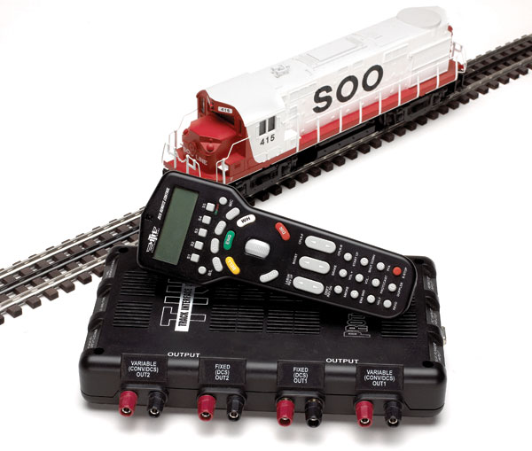
Tape actually allows you to subdivide your groups. I used two wraps of tape for specialty groups or to show things belonging to the same group but that were on a second output channel of a TIU. I picked a master color code for tape on my TIUs to identify them from top to bottom, variable channel 1 being red, variable channel 2 green, fixed channel 1 blue, and fixed channel 2 black. It makes for a good standard and you can trace that tape color throughout the whole layout. You can also tape the terminal blocks on your TIUs as a quick fix so you know where you’re at and what to look for when working on your system in the future.
I pulled my wire an extra five feet long, used contrasting tape, and would then place my number tag on top of the tape. As always, I placed at least two number tags on every bundle. I would then take those cables, cut them back, and was able to simply unbundle and retag the cable during the final termination.
Another trick that allows me to feel the difference between bundles without even looking at them is using different size wires. I used a special twisted cable that is under a common jacket for my DCS track wiring. Windy City sells this with outer sheathing that you can order factory-stripped in different colors. I used 18-gauge wire for my switches, or accessory tracks, and I used 16-gauge wire for my accessories, since I was concerned about voltage drop. However, none of my accessories draws enough power to require the higher amperage wire, and unfortunately, I learned that it is very difficult to terminate an AIU with 16-gauge stranded wire. It will fit into the small AIU terminal holes, but it’s very tedious. While this does allow me to identify groups simply by touch, I do not recommend using the 16-gauge wire for AIU wiring. A company called Anixter (800-553-3172) sells colored control cables in 18/2 and 18/3, which would be my choice for AIUs if I were to do another layout.
When I group my wiring, as I said before, I plan out my cable routes prior to all construction and bore holes throughout the support pieces of my layout. My DCS wiring was grouped together and pulled to a separate group of holes not associated with anything else. I then pulled the switch wiring throughout my whole layout, restricting that to one bored group of holes. I then came back and unfortunately had to bore multiple holes for all my AIU wiring, and simply grouped them together by like devices, picking color codes for them. Now I can walk right up to my layout, find the appropriate bundle and trace it all the way out, should I ever have a problem.
TERMINATING YOUR WIRES
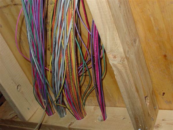
Fortunately, I have yet to have wiring problems. I’ve had wiring hanging down under my layout for almost two years waiting to be terminated. To this day I can pick my notes up, find my cable tag number, and I know exactly where to find what I’m looking for.
Plan ahead and set up the wire reels with plenty of slack. I tend to pull an extra five feet of wire and set the reels on special carts I have to hold the wire. You can do it simply with a pipe and ladder, and by pulling your cables leaving plenty of slack and putting number tags on the ends, when you come back later on, it’s no problem to identify, renumber, and terminate the wires.
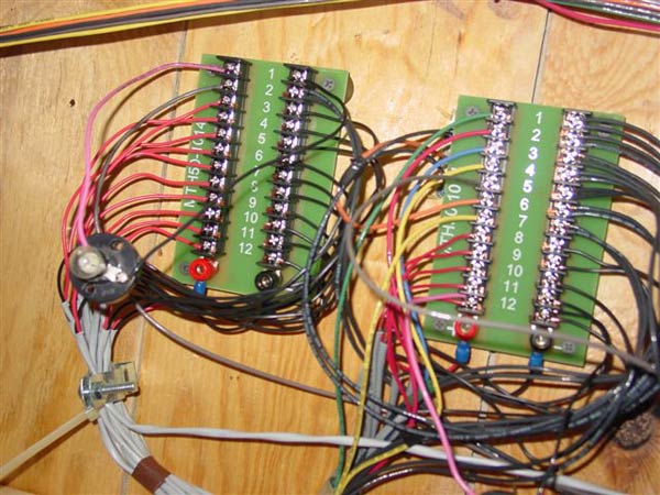
When terminating wires, I simply use a jeweler screwdriver and lay in the wire without any special fittings onto the AIU terminals. I use Thomas & Betts stakons (locking fork terminals no. RB14-10FL) for all other applications. Then I tended to use the stakons – heavy duty locking fork terminals – for terminating GarGraves track. It enables a nice tight bite underneath the rail, which is completely out of view from a finished layout. Ideally, soldering would be the best method for this, however, I’ve been quite successful terminating track using the fork terminals drilled through a small hole in the train board, stabbed into the bottom of the GarGraves track, and then caulked in place after the track is set. I then ballast over all of it, leaving no visible terminations whatsoever.
I still terminate accessories with stakons because I use stranded wire and it’s very difficult to terminate the old postwar accessories or today’s new stuff with bare wire. I use ring-type stakeons (Ideal brand ring terminal, no. 6 ring stud for 18-gauge wire, catalog no. 83-212 RV22x) for all of my postwar accessories. This allows me to quickly remove the nut on the accessory terminal and slip the wires off the stud. I tend not to use fork terminals for fear of accessories coming loose over time.
ELECTRICAL SUPPLIES
Through the school of hard knocks, I found that the following list of items from Radio Shack have enhanced my DCS layout. They’re not required by any means, however, they are very helpful for protecting the TIU, troubleshooting, and software upgrades. There may be more, but this is what I have used:
Auxiliary TIU power – 18/24vac 1000ma power adapter, No. 273-1690 with the “adapt-a-plug M” part no. 273-1716, both were about $18.95. (Set at 18 volts)
TIU output – Jacks that carry the DCS signal dual in-line banana jack, No. 274-717, four are required at $3.99 each. There is a gold-plated version at $5.99 but mine works fine and takes up less space.
TIU input – In-line fuse holders for both new and old versions of TIUs, part No. 270-1217 with 10-amp automotive fuses (10 amp 32-volt, part No. 270-1072). Keep spares! I used two and jumped my fixed input 1 to variable input 1 and fixed input 2 to variable input 2. I feed the TIU with MTH no. 40-1015 cables and the fuse link cut in. Note that the newer production TIUs (those with small REV I and REV H gold stickers on the underside) have their internal fuses on the black side. For added protection, I would fuse both the red and the black sides.
At the field terminal blocks, MTH part No. 50-1014, I use the lamp base No. 272-0357 for $1.59. This is for the “light-bulb trick” as described in the July issue of CTT and will help the DCS signal. Use an 18-volt bulb from a train shop, anything lower will quickly burn out.
I don’t have the part numbers for the stereo RCA mini jacks but they are 1/8-inch by 6-inches long. The DB-9 RS-232 cable is part no. 26-117B and costs $13.99. Both are required to do software upgrades from your computer. A new USB cable is available, part No. 26-183.
Internal TIU fuse, 20 amp, 32-volt automotive fast-acting ATM mini-blade fuse, part No. 270-1095.
The banana clips are one of the best products on the list above. I opted to use the banana-type quick-connector plugs and found them to be very effective. These have set-screw terminations, allowing a very tight fit, and the clip also offers a very tight connection to the TIU. I have found that to be very beneficial when troubleshooting my DCS. I can simply unplug the track segments and check one segment at a time. I have found this to be very advantageous, especially on the software upgrades of DCS, where you’re required to bring your TIU over to your computer to download new DCS software. Just pull the plugs and go!
I found out very early the benefits of using an auxiliary power supply for my TIUs instead of using regular layout power to energize my TIUs. It is great for software downloads. It also enables me to bring up DCS and work on features and programming in such a way that I am not required to provide power to fixed output 1, thus avoiding live track.
Using an auxiliary power supply also is quite handy for programming your AIUs, making routes, making scenes, and performing other programming tasks, stuff that you need to have the system powered to program, yet you don’t have to have tracks on. I use a power supply set at 18 volts to provide auxiliary power.
The “light-bulb trick” is a necessary evil with DCS.
You might also want a DB9 cable that I use to connect my TIUs to my home computer for software upgrades.


Interesting, but sorry it might as well be in Greek and I was an electronic tech for much of my working life. But I'm nearly 80 and also have problems with color perception. Fortunately, during my working years I knew the standard resister color code values which really helped. My small "U" shaped layout of 65 sq.ft. is conventionally powered. I use Radio Shack 18 AWG solid wire and 12 position white nylon terminal strips (I cut them to the size needed). Power feeders are 6 feet apart. Everything is wired just like I did in HO including using Atlas connectors for block control. I'm still debating TMCC and DCS.
I am just now starting to study and research DCC/DCS systems. Having worked on aircraft in the Air Force I know the importance of correctly identifying and, the proper routing of wires in any electrical system. This article gives some very good pointers/ideas on how to prevent many headaches down the road. Quite possibly avoiding them all together, an electrical system is only as functioal, as the wiring connections are good.
After all, a chain is only as strong as its weakest link. As mentioned about the fork connectors, they are a bad selection in almost any electrical system. It doesn't take much vibration for them to work loose. The ring terminals are all I will use on any wiring project, if I'm not able to use click and lock connectors. Great article!
Fantastic wealth of info on "wiring" for DCS; very useful.
I was wondering (hoping) if you would make Jamie Haislip's article about MTH DCS that was published in July 2005 issue available online as well.
Its comforting to know that there is a high techie DCS world out there, but for the average train lover who has also the Legacy, TMCC (and DCS) systems, I wish that CTT might realize this average(NESS) . Dennis Ridout should not bail out from these wonderful advances in model railroading but consider seeking "average"help as I have. Yes Virginia, there are easier to understand instructions out there.
I too am anew comer to DCS. My layout is nowhere as big and full of switches and accessories as alot of others! I bought mine from TandK hobby in Ohio.Thier elec. guru Chuck told me of a website forumn OGR with discussion groups to lighten the blow of trying to use as anewcomer! I have visited the site, however my mth engine is in need of repair to get the full enjoyment of it! the basic setup was a snap! check out the site,iam sure you will find it helpfull. lots of luck
Does DCS have to be done by jumping from one track section to the next around the track until the wires meet back at the start of the main power feed?
Great information, keep it coming, I am building a new lay out witn Lionel Legacy TMCC, however I am incorporationg DCC with it so I can then run both MTH & Lionel, I may need some help with this, I already have the DCC video.
As I recall, CTT ran an article in an earlier issue that discussed the implementation of DCS when it first came out. Does anyone recall the month/year that article was run? It was followed up by another article shortly afterwards. I don't believe it was an official "Part 1, Part 2" type article though. Can anyone help??
Steve Toth
Mesa, AZ
I have DCS and it is just too complicated for me. It has taken all the joy from playing with my trains. Its for sale
As always CTT has been very helpful. I keep my back issues for constant reference. I will continue to suscribe to CTT for its valuable information.
Dennis