


There is more to understanding railroad wayside signals than simply “green means go, red means stop.” To appreciate what the signals you see along the track are telling you, you first have to grasp a few basic concepts. Railroad traffic control boils down to three situations: trains running in the same direction on the same track; trains running in opposite directions on the same track; and trains running on two tracks that intersect.
One of the first types of traffic control was the timetable, which specifies where each train should be at a given time. To cope with unforeseen circumstances — delays, breakdowns, extra trains — the dispatcher issued train orders, which supplemented and superseded the timetable.
Another type of traffic control is to divide the line into sections or blocks and permit only one train in a block. Initially, the system required a person at each end of each block to record trains entering and leaving the blocks, and a way for them to communicate with each other. The manual block system still exists on many lines but with different names and different technology — the communication is by radio.
Manual block signal indications were simple: stop, the block is occupied; proceed, the block is clear; and proceed at a restricted speed prepared to stop short of a preceding train. Because trains had to approach each station prepared to stop, the “distant” signal was developed to give an advance indication of whether a stop was required at the “home” signal.
WHAT SIGNALS DO: TWO TYPES, TWO FUNCTIONS
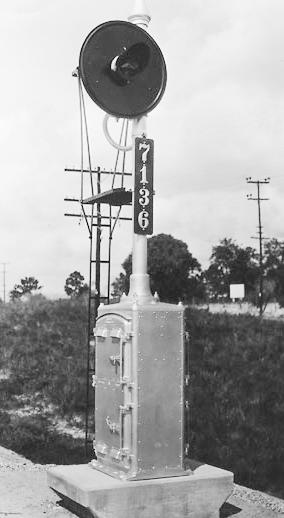
There are two types of signals, permissive and absolute. You can tell if a signal is permissive or absolute by looking at it. The rules vary by railroad, but permissive signals usually have a number plate on the base of the mast on which they’re mounted, or the letter “I”. Absolute signals do not have the number plate or will have the letter “A”. The location of the signal is also often a clue to its type.
Signals have two purposes, protection and control. Permissive signals only provide protection. Absolute signals provide both control and protection. Functionally, the basic difference between permissive and absolute signals is the most restrictive type of indication each can display.
A red permissive signal means stop and proceed. After stopping (which is no longer required on some railroads) the train can proceed at restricted speed until a more favorable signal is reached. (Restricted speed is usually 15 or 20 mph, being prepared to stop upon sighting any obstruction or problem.)
But a red absolute signal means stop – and stay stopped. The only way to pass a red absolute signal is with the dispatcher’s verbal permission or, in rare circumstances, under the protection of a flagman.
(To see a glossary of signal terms, see the link at the bottom of this story.)
Permissive signals and automatic block signaling
Permissive signals respond to track occupancy.
The invention of the track circuit in 1872 by William Robinson permitted automatic block signals. Most simply, a low-voltage battery current runs up one rail and down the other. As long as current flows from the battery through one rail to the relay and back through the other rail, the relay remains energized and routes current from another battery to the green lamp of a clear signal. But when a train is present, the circuit is short-circuited by the steel wheels and axles of the cars; a broken rail or an open switch will also break the circuit. As a result the relay is opened and the signal displays red. The system is arranged so the failure of any component results in a red indication or a dark signal (which must be interpreted as the most restrictive aspect that signal can display).
The Automatic Block Signal (ABS) system permitted much shorter blocks than the manual block system and had the effect of increasing line capacity. The distant signal proved just as useful for the automatic block system as for manual block. It became common practice with lower-quadrant semaphores to place the home signal for the immediate block and the distant signal for the next block on the same mast.
An automatic block signal system is composed of a series of block signals. Except where a current of traffic has been established on a track and Rule 251 movement authority is in effect, permissive signals and ABS do not authorize the use of, or movement on, the main track. Their role is that of protective overlay: an added layer of protection placed on the operation. If a train violates its movement authority, it and a conflicting movement will both soon encounter red permissive signals, resulting in much embarrassment, but not an accident.
As a practical matter, Centralized Traffic Control (CTC) territory always includes ABS as a protective overlay. Territory controlled by Track Warrrant Control (TWC), Direct Traffic Control (DTC), or Form D Control System (DCS) may or may not include an ABS overlay; this commonly depends on the traffic volume of the particular line. Herein lies a unique circumstance: A train can be at a green signal in TWC territory and be unable to proceed, unless it also has a track warrant to do so. Likewise, it can be facing a red permissive signal and yet proceed at restricted speed if it holds the proper TWC (or DTC, DCS, etc.) movement authority.
Block signals are often “approach lit” to conserve bulbs and electricity. They remain dark until the approach of an oncoming train is detected, and are illuminated only when a train is in the block that the signal faces. The circuitry is more complicated, but lamps last longer and power consumption is less.
Absolute signals and interlocking signals
Absolute signals are most often used at interlockings or in CTC territory where it is desired to control when, and if, a train passes a signal. Absolute signals are found at railroad crossings and drawbridges, and at places where trains pass over powered switches, such as at the ends of sidings or at main track crossovers. For two lightly trafficked rail lines in a remote area, stop signs may be sufficient as a type of absolute signal. However, just as four-way stop signs are an inefficient way to control the intersection of two roads streets, stop signs are not efficient on rail routes with heavy traffic.
When a train enters a siding and stops at the red absolute signal at the far end, the dispatcher obviously does not want it to “stop and proceed” down the line toward an oncoming train.
Usually the signals are manually controlled from a remote office. Outside CTC limits, a sophisticated ABS system that can detect train direction also will use them to protect movement between sidings. Such a system is termed an Absolute Permissive Block System.
Absolute signals usually “wear two hats” by also functioning as block signals to protect trains from colliding with each other, although they do not permit trains to pass a red signal after stopping. For example, in single-track CTC territory absolute signals protect the switches at the ends of sidings; permissive signals are placed at 2-3 mile intervals along the single track.
READING SIGNALS: ASPECTS AND SIGNAL INDICATIONS
The lights displayed by a signal have three properties: aspect, name, and indication. The aspect describes what is displayed, e.g., red over green. The name is the formal name classification for that signal, e.g., diverging clear. The indication is the instruction conveyed by the signal.
A train crew seeing a signal with a yellow aspect will understand they are nearing an approach signal, which conveys an indication that might mean “proceed prepared to stop before your train passes the next signal; trains exceeding 35 mph must immediately reduce to that speed.” (There’s more to it than simply “the next signal is red.”)
![]() All railroads use the common red, yellow, and green aspects, although the indication of the yellow (approach) signal varies from road to road. Many other color combinations are used. Some are common, others are unique to a specific railroad.
All railroads use the common red, yellow, and green aspects, although the indication of the yellow (approach) signal varies from road to road. Many other color combinations are used. Some are common, others are unique to a specific railroad.
The most constant signals and the easiest to understand are single-head block signals. Red means stop; green means proceed, and yellow means caution or approach, usually indicating that the next signal is red. Four-indication block signaling usually uses either a flashing yellow aspect or two signal heads showing yellow-over-green or yellow-over-yellow to indicate two blocks clear (“advance approach” or “approach medium”).
Block signals are normally clear. About all they can tell a train-watcher is that a train has just gone past or, on a single-track line, that there is something coming (from behind the observer), though not necessarily in the block-most automatic block systems are arranged so that a moving train will set signals at stop in front of it as far as the next siding.
The two- and three-head signals found at interlockings are more complex. All red means stop. That’s universal. For other aspects, the general principle is that green on top means main route or normal speed, and red over green or yellow indicates diverging route or medium speed.
Interlocking signals are normally set at stop. Any less restrictive indication means that a route has been set up through the interlocking – in other words, something is coming. The preceding block signal usually serves as the distant signal for an interlocking. It will normally indicate caution; if it is clear, it indicates that a route has been set up through the interlocking.
The chance for each road to show its individuality comes with such things as flashing lights, white lights, blue lights, and dark signal heads.
Signal aspects, names, and indications once were shown in the rulebook, but because of rulebook consolidation and the increasing differences between roads, many railroads now show them in their employee timetable.
See the bottom of this page for a PDF containing Atchison, Topeka & Santa Fe Ry. Rules of the Operating Department, 1958.
HARDWARE: DIFFERENT TYPES OF EQUIPMENT
Over railroading’s long history there have been many types of signals, using a variety of means to transmit their messages. Several designs are in use today.
Ball signals
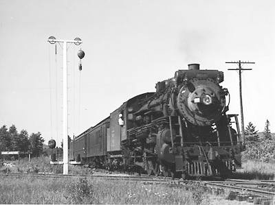
The first U.S. signal installation was on the New Castle & Frenchtown Railroad in 1832. The NC&F signals were peach baskets suspended from masts by pulleys. By their position (high, middle, or low) and color (black or white), they conveyed information to trains and stations, whose staff observed them with telescopes.
With refinements, this “ball” type signal became widely used, its aspect for “proceed” giving us the stirring term “Highball!” The last ball signal in service is found at Whitefield, N.H.
The mid-19th century saw development of other manual signal types. Later, electricity was used to actuate signals powered by clockwork mechanisms. There were also electro-pneumatic types. All-electric designs came to be standard for automatic signals.
Semaphore signals
Perhaps the most classic of all railroad signals, the semaphore, came into general use in the 1860s. This type, based on an ancient form of communication that used a moveable “arm” or “blade,” soon became by far the most common signal.
Various signal indications were conveyed by setting the blade in different positions. The problem of night visibility was addressed by using lamps in conjunction with the blade. Semaphores were constructed with castings in which were set red, yellow, and green lenses, which were moved in front of a single white light (oil at first, later electric) as the blade moved.
At first, the “lower-quadrant” semaphore design was used – the blade moved in the lower-right portion of an imaginary circle whose center was the blade’s pivot point. Most lower-quadrant semaphores had two aspects: A horizontal (raised) blade meant “stop;” a blade hanging down about 60 degrees from horizontal meant proceed. Lower-quadrant blades had to be counterweighted so they would go to the horizontal position in case of failure of the controlling mechanism. Although there were three-position lower-quadrant semaphores, the two-position Union Switch & Signal “Style B” of 1898 (usually employing two arms) has come to be the best known.
Shortly after the turn of the century, the three-position (vertical, diagonal, horizontal) upper-quadrant semaphore was introduced. It had three aspects: horizontal for stop, 45 degrees above horizontal for caution, vertical for proceed. In 1908 this type became the standard for new installations. Such signals still exist on several roads. With the advent of light signals, semaphores came to be seen as inherently inferior, since they used two different aspects – blade position by day and light color by night – to convey their message. Also, their relatively numerous and heavy moving parts made them less attractive from a maintenance standpoint.
Color-light signals
The need to provide signals in subway tunnels led to the development of color-light signals in the first decade of this century. While lights had been used for years with semaphores, their exclusive use in high-speed, main-line applications became feasible in 1914 with the perfection of concentrated filament lamps, giving satisfactory sighting distance in daylight with moderate power consumption.
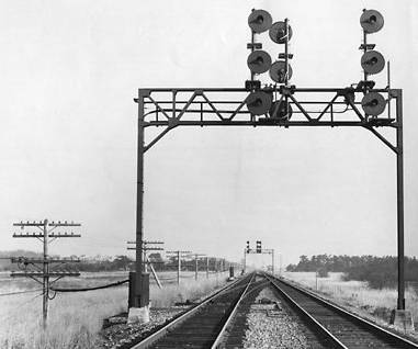
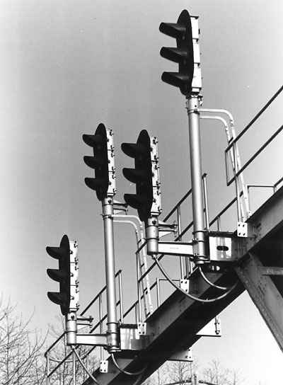
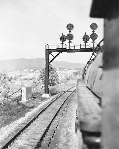
Color-light signals consist of three bulbs shining through three lenses, or “roundels,” one each red, yellow, and green. Typically, the lights are grouped vertically with green at the top, exactly opposite of the highway traffic signals that protect road intersections. Next most common is the triangular arrangement. Some roads, like Chicago & North Western, used a horizontal grouping.
Unlike semaphore lights, color-light signals are equipped with visors so sunlight reflections will not give false readings. Union Pacific fits its “tri-lights” with large hoods for this purpose.
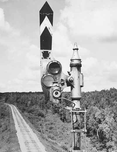
Searchlight signals
The searchlight signal – which uses a single lamp with a system of movable lenses to project three colors – first appeared in 1920. Lens improvements in 1930 made signals with a 1-mile range and low power consumption possible, and the searchlight found widespread use.
A relay-type mechanism moves colored lenses in front of a white light, not unlike a semaphore. To achieve long range, the light beam is very intense and narrow, and must be precisely aimed for best visibility from approaching locomotive cabs.
To many, the searchlight’s simple, clean appearance made it a perfect aesthetic complement to the streamliners and diesels the railroads began to embrace in the 1930’s. Today, the low power consumption of its single light has come to be offset by the high maintenance cost of the movable lens system, so that now trilight signals are preferred for new installations and are replacing searchlights in many places.
Position-light signals
Developed by the Pennsylvania Railroad and introduced in 1915, the position-light signal saw use only on the PRR and affiliated lines like Long Island, Norfolk & Western, and Lehigh Valley. In this design, high-intensity lights of a single color (a fog-penetrating yellow) are illuminated in rows of three, forming lines not unlike semaphore signals.
A fully equipped signal head can display lights in horizontal, vertical, and two diagonal rows, but partial units are common, especially in cases where two heads are used. (PRR also had special X and circle aspects.)
While a relatively large number of lights was needed for each unit, the signal could still be read with one light in a row burned out.
High maintenance, and the fact that they do not use the standard red-yellow-green colors, mean that position-lights are now being phased out.
Color position-light signals
First used in 1921, color position-lights are as identified with Baltimore & Ohio and its related lines (chiefly the old Alton lines) as the position-light is with the PRR. Unlike the position-light, this type has no center lamp and uses larger lenses of three colors. The two lamps in each row are green (vertical), yellow (diagonal), and red (horizontal). The basic design often is modified with lunar white or yellow markers above and below the main head.
Although more costly than some other signal types, a color position-light signal has the advantage of redundancy: it displays its message in two ways: the position of the lights and the color of the lights. As with position-light signals, the color position-light signal can be read with one light in a row burned out.
On the Northeast Corridor, Amtrak is converting position-light signals to color position-lights by removing the center lamp and changing the remaining lenses to color types.
Cab signals
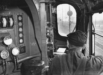
Some railroads use cab signals (small signals in the locomotive cab) to supplement or even replace wayside signals. These may be associated with an Automatic Train Stop System (ATS), which requires acknowledgment and/or observance of signals.
Cab signals and ATS are yet other types of protective overlays, created to keep trains apart and operations safe.


Cab signals are particularly valuable when running in territory that is frequently foggy; e.g., the PRR’s Old Main Line west of Philadelphia.
Flashing red indicates Restricting. Trains may pass this signal without stopping, prepared to stop within one-half the range of vision.
A question instead of a comment. I was watching a video on Youtube, of the Santa Fe mainline in Arizona in 1992 and I noticed a signal aspect I’ve never seen before. Part of the video shows a signal bridge with searchlight signals, west of the location of where the camera is set up. The signals and aspects are easily seen. The train passes and the camera pans west to follow the train. The train passes under the signal bridge and the clear drops to a flashing red instead of solid red. My question is; what does the flashing red aspect mean? Thank you.