This month I decided to try planning a Layout Design Element. According to Model Railroad Planning editor Tony Koester, who invented the term, a Layout Design Element (LDE) is a visually and operationally recognizable model of a prototype railroad location. An LDE is a notch of realism higher than layouts that are merely inspired by a prototype. Track arrangements, structures, and scenery must hew as closely as possible to the real thing.
My home layout models the Cincinnati, Lebanon & Northern, a 26-mile-long Southwest Ohio short line, just after the turn of the previous century. I model it in 1906, a couple years after the Pennsy bought and standard-gauged the line but before it fully subsumed the CL&N’s operations and identity. So I was over the moon when I learned that the Library of Congress had posted online tens of thousands of Sanborn Fire Insurance maps, including a set showing Warren County, Ohio, in 1907. Sanborn maps are treasured by model railroaders because they show not only streets and railroad tracks, but also building footprints, their construction materials (wood, brick, concrete), the names of businesses, and sometimes even the functions of individual buildings within an industry. For years they were only available from Sanborn, university libraries, and historical societies, and they often cost a pretty penny. Now, though, you can search a trove of Sanborn maps online at the Library of Congress’ website and download them in high resolution for free. That’s a printout of the Sanborn map of the CL&N’s Lebanon trackage behind my sketch in the photo above.
A map of the same area in 1903 was reproduced in the definitive history of the CL&N, Narrow Gauge in Ohio by John W. Houck. I had based my HO scale version of Lebanon on that map (with some modifications to make it fit in 8 linear feet). However, I noted some differences between it and the Sanborn map. On the latter, the southernmost yard track connected to the main at both ends, rather than stub-ending at Broadway. Two short industrial spurs and a turntable shown on the 1903 map were missing from Sanborn’s. And missing from the 1903 map was the Lebanon Canning Co., a sizable industry I would have included had I known about it when I built my layout.
It seemed plausible to me that the southernmost yard track might have been connected to the main on the east end and the two short spurs pulled up in the four years that separated the two maps. And the section of the Sanborn map that showed the cannery was so close-up that it didn’t even show which end of its spur connected to the main. So it was likely the turntable was in an undepicted area farther east. I decided I would design my LDE of Lebanon based on the Sanborn depictions of the track and structures.
Since this is just a sketch, not a plan that will be built in a specific space, I could generously give myself 10 feet in which to work. Even so, it took me four drafts, being forced to leave out elements each time, before I came up with a plan I was satisfied with.
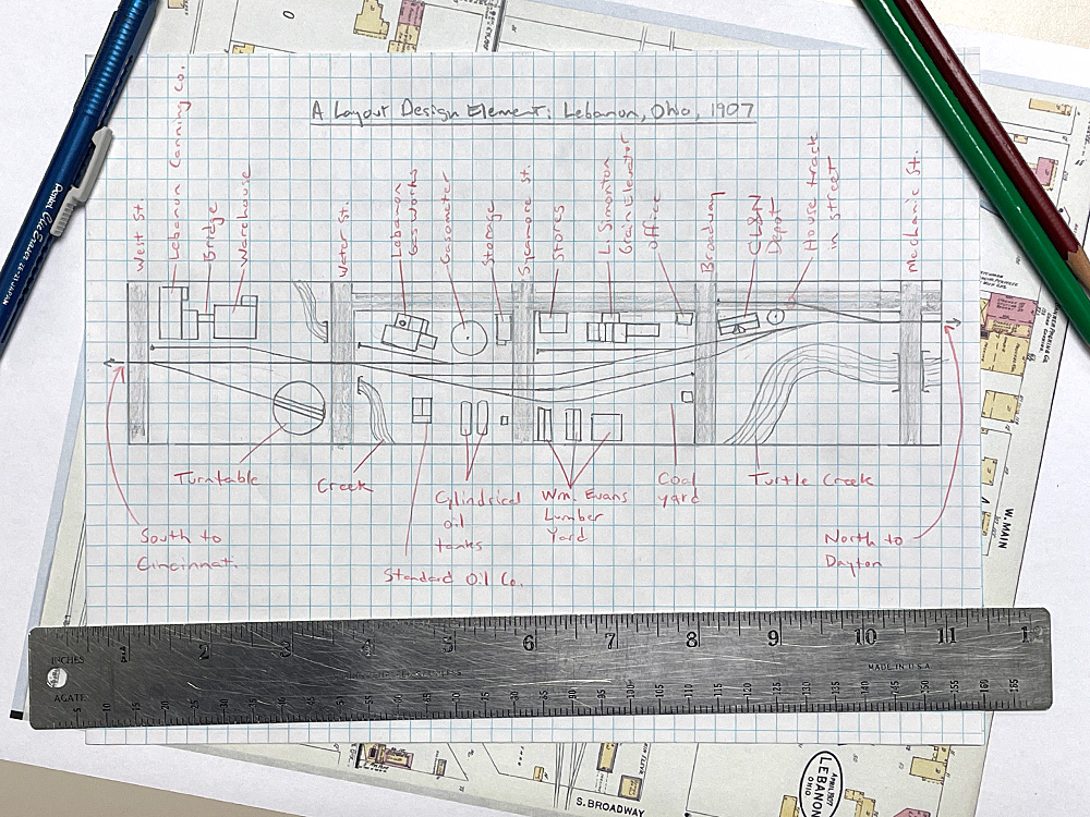
I started by selecting which part of the map I would draw and sketching in the locations of the streets that would cross the tracks. Although I started out drawing everything between West Street and East Street, beyond which the railroad condensed to a single track in each direction, my final draft cuts off west of Mechanic Street. Though I would have liked to include the team track in the street between Mechanic and East, I couldn’t spare the space. I likewise had to omit Clay Street and the western crossing of Turtle Creek. They would have been nice to include scenically, but they didn’t add anything to the track plan operationally.
When I planned my version of Lebanon, I guessed at the purpose of the spurs shown on the 1903 map. I included a grain elevator, a tobacco warehouse, a coal dealer, a creamery, and a farm implement dealer – all important businesses in 1906 Lebanon, according to the book. The Sanborn map, however, showed me what those rail-served industries actually were. To the west was the cannery; not knowing which way the spur connected, I decided to face the turnout with the points east, so as not to interfere with the lead to the turntable.
According to both maps, the yard ladder begins east of Water Street. North and south of the yard on this block are two industries, one I knew about, and the other of which surprised me. The former, to the south, was Standard Oil; the Sanborn map showed me the position of its small building, pump shed, and two horizontal steel tanks. I had no idea that north of the main, on its own spur, was the Lebanon Gas Works, a coal-gas plant. Since my plan had less space for the spur than the prototype, I had to swap the positions of the main building and the large circular “gasometer.” But I was pleased to be able to include this unusual industry when planning a Layout Design Element of Lebanon.
Between Sycamore Street and Broadway, the town’s main drag, four businesses flanked the CL&N’s tracks. To the south was the Wm. Evans Lumber Yard, with two trackside lumber sheds. Since my plan was only 2 feet deep, I moved the lumber yard’s headquarters north from its actual location on Chillicothe Pike. Alongside that on the Sanborn map was an area labeled “Coal Yard,” with one small building.
On the stub-ended spur north of the yard was the L. Simonton Grain Elevator. The Sanborn map conveniently listed the industry’s equipment and capacities: two elevators, one corn sheller, one corn cleaner, one wheat cleaner, one clover seed cleaner (used to plant forage for livestock), and storage for 14,000 bushels of wheat and 2,500 bushels of corn. Corn was a big crop in the area, but much of it went to the many canneries in the area. There was another building in the same block as the grain elevator, but since it wasn’t labeled or rail-served, I decided it would be a store.
Between Broadway and Mechanic Street lay the CL&N’s combination depot and a water tank. The rails of the house track north of the station were laid in the street. The Sanborn map doesn’t show what’s south of the tracks, but since the 1903 map shows Turtle Creek arching up close to the yard, it’s likely there’s nothing else there. Including this water feature and road bridge will give the otherwise urban LDE some welcome scenic interest.
So am I happy with how I planned my LDE? More or less. Ideally, I would have given myself about twice as much length to allow larger industries, longer yard tracks, and gentler turnouts than the no. 4s that I used. But when it comes to accurately depicting a visually and operationally recognizable representation of Lebanon, Ohio, in 1907, I think I succeeded. For more help in planning a Layout Design Element for your model railroad, check out any issue of Model Railroad Planning. The 2023 edition of this annual special issue is available for pre-order now.