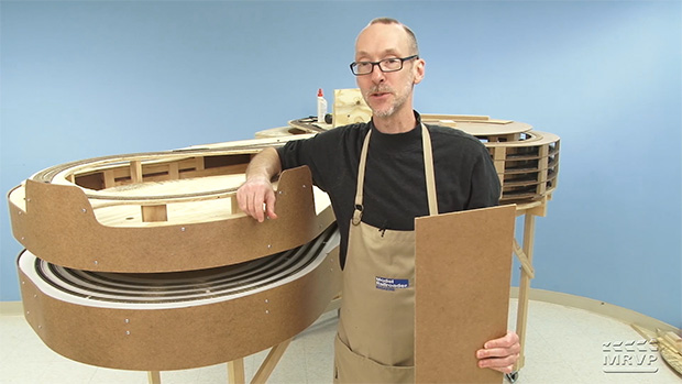
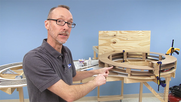
Canadian Canyons Series: Part 11 – Laying track on the helix
| Last updated on February 2, 2021
Trains.com is undergoing website maintenance that is expected to last approximately two weeks. Click here to learn more.
| Last updated on February 2, 2021
Members enjoy 15% off any purchase in our store. Join Today!
Model Railroader 2026 Calendar
Don't miss Model Railroader’s all-new 2026 calendar, featuring Rod Stewart's spectacular layout!
David why did you use cork in the helix
Really enjoying this series David. Obviously patience is a MUST! But with the proper tools and again patience, one can see when completed the satisfaction of both a neat railroad and a sense of accomplishment will be there. Thanks again and can’t wait see more! As I mentioned in an earlier post, my current layout is based on your 2010 project railroad and I’m truly enjoying it. But this or something similar is in my future.
David, how about a followup on KJ’s Garden Railroad on how all that work last summer survived the winter? Inquiring minds want to know.
In reply to Don Martin – Interesting use [adapt and overcome comes to mind when modelling!] but not sure it would be supportive enough without a lot of support columns added. I was wondering if you could use pegboard instead if you can’t find a clean sheet of tempered hardboard. Most Lowes, Home Depot or Home Hardware here in Canada seems to supply it or at least can order it in for you. Rigidity would be the same and it would provide ready cut holes for a variety of wiring if you factored in that height to your upright blocks??
David, would it be easier to preform the curves ahead of time before you solder the track together then lay your caulk down?
Great series as always. There are those that favor ballasting all track including hidden areas, do you intend to do that? If not why?
Phil Poirier
David, Great video on laying track on the Helix. However I do have something that is driving me crazy watching you do this, and that is the soldering technique you are using.
I was an electronic engineering technician for 12 years and was trained on the proper soldering techniques for electronic circuitry by the best in the industry. The technique you are using will render cold solder joints, which in turn cause high current flow which can cause damaged electronic components and even fires.
The proper technique for soldering electronic circuitry is as follows:
1. Your soldering station should have a sponge tray. Wet the sponge and wring it out so it is damp, and keep it damp.
2. Clean the HOT soldering tip on your iron by rubbing it across the sponge until it is shiny. If it will not get shiny then tin the tip after cleaning it with fine sand paper. This way each time you go to use the iron you wipe it across the sponge first. This assures the tip is clean and transmits the heat more efficiently, which is important for a good clean solder joint.
3, VERY IMPORTANT place the soldering iron tip on one side of the joint you are going to solder and the solder wire on the other side of the joint. DO NOT place the solder on the tip of the soldering iron. This heats the joint you are soldering so the solder when touching the joint melts and flows freely into all orifices giving you a good conductive solder joint. Melting the solder with the iron makes the solder hot but leaves the joint to be soldered cold and the solder does not flow or adhere properly rendering a cold solder joint and bad conductivity creating higher than normal current flow causing damage and possible fires.
4. You can identify a good solder joint by the shiny surface of the solder and the even flow of same.
5. You can identify a cold solder joint when you see the solder bunched up and grey looking, It will not have a smooth flow to it and will not be shiny.
I hope this is of help to you as I know that you want to demonstrate the proper techniques in all that you do on the videos and following this technique will assure that you are successful in doing so. Also it will no longer be aggravating watching you solder. LOL 🙂
p.s. I love all your videos on MRVP as well as Model railroader magazine.
Thanks to all of you at Model Railroader,
Jim Tanner
Jefferson, Ohio
(As long as I’m here — one issue I have with MRV+ is that you guys make it take a bunch of extra clicks to watch a series in order. Why does, say, Canadian Canyons Series: Part 9 not have a convenient link to Part 10 once that part goes up? Instead all the links are to previous episodes of the series. Surely the next episode is the most likely one for people to look for, no?)
Yet another video where you guys make something that I considered utterly beyond my capabilities look pretty easy to do. Bravo!
Good work David… glad to see this video posted as I’ve watched the progress via the web cam and wondered how you did all of the fine tuning. Running the wires under the inside track is prototypical of mainline railroading. Making adjustments with extra supporting blocks also gives us modelers an ego boost knowing we’re not the only ones who have to adapt as we progress on our own layouts. Hope this layout is featured at Trainfest 2017 if not the Olympia or possibly both? Onward!
I should have waited for episode 11. You did have a 1/16″ difference at the transition from plywood to hardboard. It got sanded off after the helix was assembled. Now that I think about it is easier then trying to do it before assembly. Silly me.
Hi David,
great work – I’m very excited b this project. Can you explain more about why and where the wiring is, the blocks isolation point, etc? I don’t know if others understood it, but I didn’t quite get it. Maybe future episodes will reveal more and it will all make sense then.
Thanks
This is a very interesting series, it almost makes me wish I had started I “n” scale. Keep up the great videos I can apply most of this to HO
David I had a similar issue when I built my previous N Gauge layout with a helix, the way I overcame the problem of the Peco flex track wanting to return to its straight form was to use another product from the UK called Tracsetta. These are for keeping flex track either dead straight or on a preset radius.Putting a curved one at the end of the flex track kept the whole track in shape until the adhesive had cured.
At least there was no “UP! UP! And Away!” as the train climbed to the end of the known world. You didn’t mention, but I presume that there were/are more track feeders on the helix than shown.
Nicely done. Always a pleasure to watch your videos.
Coming along nicely!! A very ambitious project and a very informative series. I’m really enjoying this. Thanks!!
Why did youse glue for the roadbed instead of Cauk?
I’ve been looking for tempered hardboard here in Canada and finding it seems to be a problem (at least in decent sized sheets). I’ve been thinking of doing a helix but using “foamboard” that you get from Staples. It is 3/16″ with thick paper on each side and thin foam in the middle. I’ve used this for elevated sections and it seems to work well, is nice and thin and very light. It may need a few more vertical risers than the tempered hardboard but by cutting small pieces of the foamboard I’m thinking I could accomplish that.
The biggest problem with it is that it does not come in large sheets. It only comes in 20″ X 30″ sheets (but a sheet only costs C$4.00). With sheets that small I’d likely have to cut something like 4 quarters to make one full rotation.
And, to save space at the joints I think I’d try to fabricate a biscuit of some sort instead of the plate underneath. Perhaps use something like round toothpicks.
Stalactites grown down from the “C”eiling. Stalagmites grown up from the “G”round. So in this case, those nails coming through the tempered hardboard would be “Stalactites”.
David, as usual, a really informative video. At one point, you almost looked like Eric White? Can’t wait for the next edition.