
A ll right, I’ll fess up. Wiring is not my strong suit. I grew up with AC tinplate trains and still find even that a little challenging. I understand the principles of DC cab control wiring, and I’ve read all of Kalmbach’s wiring books as well as pretty much every article Model Railroader has published on wiring, electronics, and Digital Command Control (including Bruce’s Chubb’s and Keith Gutierrez’s early features on command control). Between 1978 and 2007, I served as both a magazine and book editor at Kalmbach Publishing Co., so that’s what I was paid to do!
Reading and doing, however, aren’t exactly the same.
When MR’s editors called about this project, they gave me the choice of using block wiring, but they preferred Digital Command Control (DCC). Progressive (and maybe a little lazy) person that I am, I thought about it briefly and opted for Digitrax DCC. My reasoning? In theory, DCC requires only two wires from the command station to the rails, and that’s it. In theory.
Idiot-proof DCC
In fact, I learned to my considerable pleasure and relief, it really didn’t take much more than that. Also to my pleasure and relief, the trains ran just fine the first time I fired up the N scale Salt Lake Route layout. I’d gotten it right the first time! (I’m still a little surprised that the trains actually run when I turn on the power.) That being the case, I can only assume that DCC, at least in this simple form, is pretty much idiot-proof.
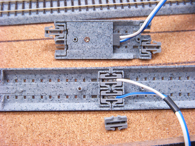
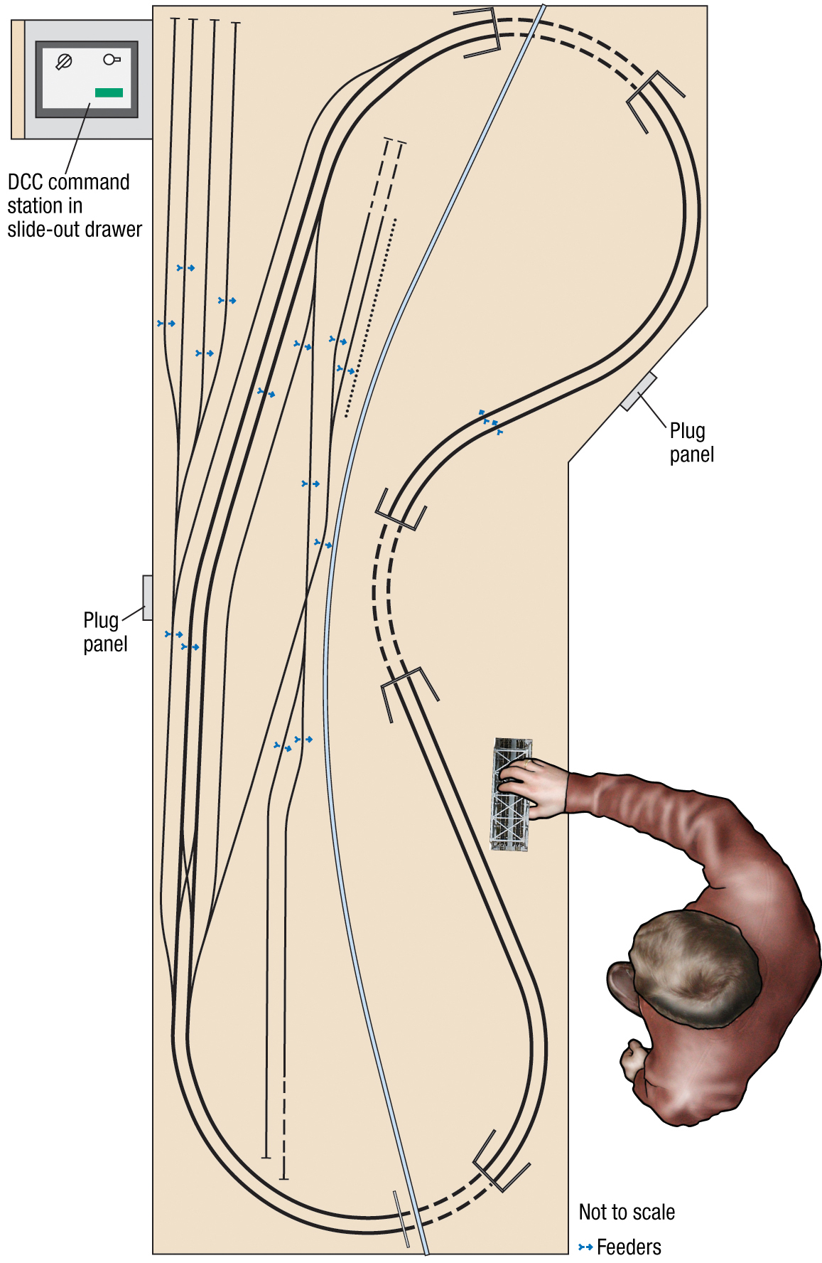
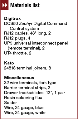
This layout uses Kato Unitrack, but the firm doesn’t offer a DCC system. However, its DC plug-and-play control system is as close to foolproof as you could make it. If you’re using Unitrack but really not interested in DCC, go ahead and use Kato’s DC wiring system. The turnouts are power-routing, and Kato sells insulated rail joiners to make block wiring easy. The feeder tracks and the combination feeder joiners/clips, seen in fig. 1, come ready to plug in; Kato also offers extension wires for longer runs. Though I wired the Salt Lake Route for DCC, much of what follows applies to both DC and DCC.
Once you’ve removed both of the original connectors from the end of the appropriate track sections, simply insert Kato’s feeder connectors into the openings molded into the roadbed and push on them until they snap into place. Once again, be sure to orient the blue and white wires to the correct rails to avoid an accidental short circuit from reversed polarity. I cut off the large plug from the opposite end of the blue and white wires and fed them through the holes I drilled in the layout’s surface. I left the wires hanging until it was time to connect them.
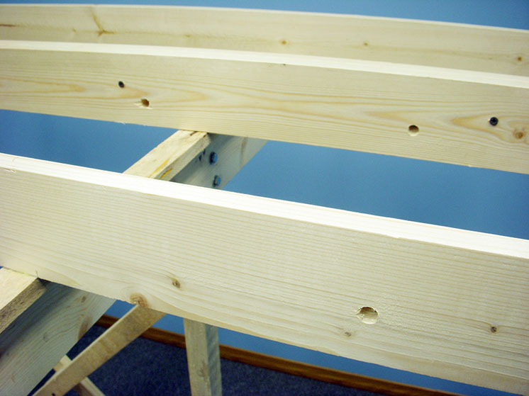
By the way, because of the way my friend, Stener, and I designed the folding benchwork, nothing can be allowed to hang down between the layout’s L-girders. That space is reserved for the leg assemblies. That being the case, we drilled a couple of ½”-diameter holes through each joist, fig. 2, and ran the wiring through these holes to keep it neat and clear of the folding legs.
Turnouts
Kato’s switch machines are hidden under the turnout inside the molded roadbed. A small black tab next to the points actuates the turnout manually. The tab is unobtrusive and blends into the background. The turnout’s action is positive, and the points make good contact with the stock rails. I had to use a small file to smooth the points a little on only two of the dozen turnouts I used (not including the crossover).
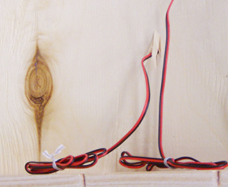
Like the feeder sections, the turnouts come with wires attached – one black, one red, and a big plug. As with the feeders, I trimmed off the plug so I could feed the switch machine wires through a small hole in the layout surface under the turnout. I left the blue and white track feeders dangling, but since I wasn’t going to wire the switch machines (the turnouts all can be aligned manually), I fed the red and black wires through the plywood, coiled them up, and tacked them to the side of the joist so they’d be out of the way. See fig. 3. I was careful to keep the staples from penetrating the wire insulation to avoid any potential short circuits.
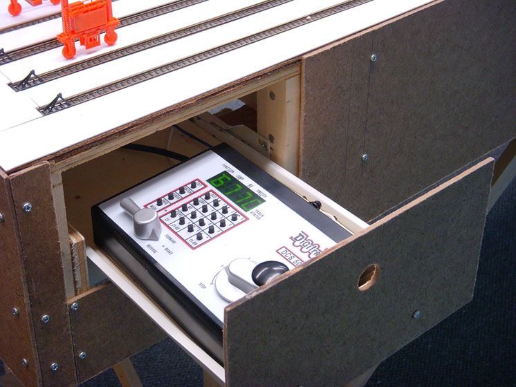
Command station drawer
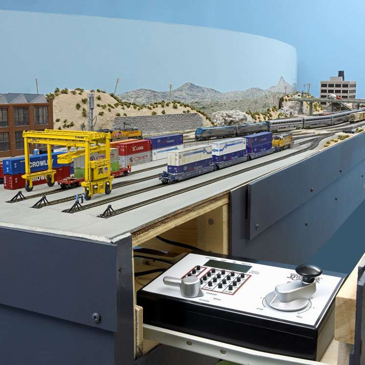
Since all of the switching activity will be happening on the yard side of the layout, that seemed like the logical location for the DCC system’s command station. Unfortunately, that’s the side with the least space available. The area where the benchwork flares out on the Meadow Valley Wash side would be ideal, but that’s open country and the trains just pass through without any reason to stop.
I located the DCC system in a drawer under the left end of the intermodal yard beyond the legs, as shown in fig. 4. I bought a pair of drawer tracks at the local home improvement center, used a piece of leftover plywood for the drawer bottom, and attached a piece of scrap 1 x 2 and the Masonite I cut out from the side as the drawer front. I wanted everything on the fascia flush, so I drilled a hole in the drawer front to serve as a drawer pull.
Bringing it all together
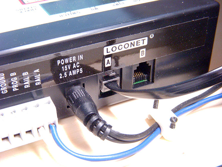
Remember my comments about attaching two wires to connect the DCC to the layout? I ran a pair of 16-gauge bus wires, one blue and one white, from the Digitrax command station to a pair of barrier terminal strips mounted on a joist under the layout.
I could have run bus wires under the tracks and connected the feeder wires (indicated in fig. 5) to those. I know some modelers like to use the suitcase connectors (Scotchlok insulation displacement connectors) for this purpose. However, I was unable to find any small enough for the 24 gauge wires.
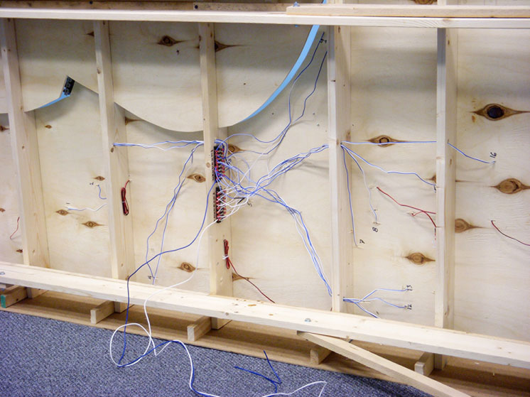
The layout is actually at a reasonable height for wiring. I was almost able to sit in a desk chair lowered as far as it would go – almost, but not quite. So I began the wiring process on my hands and knees with my head bent back, which wasn’t very comfortable. When I was about halfway done, my wife, Diana, came down to the basement to check on my progress. She asked, “How about folding the legs up and tipping the layout on its side?” A great idea. In fact, it was such a great idea that I was able to wire the layout more comfortably. See fig. 6.
I numbered each pair of feeders at the point where they came through the plywood; I also numbered each of the connection points on the terminal strips. This probably isn’t necessary on such a small layout, but it’ll help in troubleshooting if problems arise later.
Back to the two wires from the DCC command station. One of the terminal strips is for the blue wires; the other is for the white. See fig. 7. These particular strips have continuity from top to bottom, but not side to side. To use them as I have here, I stripped a couple feet of insulation from the end of both the 16 gauge white and blue wires.
After loosening all of the lower screw terminals, I looped the bare wire over the first screw, pulled the insulation up close to the terminal, and tightened the screw. Then I looped the bare wire up and around each screw in turn and tightened the connections as I went along. That made all of the screw terminals live. Then I did the same with the white terminal strip. Later on, I found out that most terminal strip manufacturers sell bridge connectors that fit under the screws to do this job.
Tiny wire troubles solved
I could have just stripped the insulation from the ends of each of the stranded feeder wires, wrapped them around the terminal screws, and tightened them down. But I was a little bit concerned about stray strands of wire causing a short circuit. So, I bought spade lugs to make everything more permanent and neater. However, the openings in the smallest spade lugs were too large for the wire, so there wasn’t any way a crimping tool could squeeze the lug onto the wire tightly enough for a good connection.
To resolve this problem, I stripped about an inch of insulation from the end of each wire, folded the bare wire over on itself at about ½”, and twisted it – effectively doubling the gauge. I fed that through the hole in the shank of the spade lug, tinned it, and soldered it. This trick would probably work just as well with a crimping tool, but I didn’t have one so I went with soldering the joints. They’ll hold forever.
At this point, finishing the wiring was just a matter of sliding the spade lugs under the appropriate screw terminals and tightening them down. Having done that with all 16 feeder pairs, I set the layout on its legs, plugged in the command station, and placed a decoder-equipped locomotive on the track. Much to my pleasure, it ran smoothly everywhere! Next, I added a second DCC locomotive to the track, punched in the locomotive’s address in the DCC system, and ran it around the mainline loop in the other direction at the same time.
You may be asking yourself, “Why 16 pairs of feeders? Why not just one pair?” The Kato turnouts I used are power-routing, so if I want to enter a siding, the turnouts at both ends must be lined properly or the siding will be dead. With DCC, all of the track can be live all the time. So, feeder wires need to go to each side of the double-track main line on the Meadow Valley Wash side of the layout. On the more complex yard side, I installed 14 pairs connecting to the main lines, the passing sidings, the intermodal tracks, the industrial sidings, the engine servicing tracks, and both sides of the crossing.
Remote control
Were I to build this layout for myself, I probably would have been content to run the layout from the command station alone. But MR’s managing editor, David Popp, observed that it would be good to have a socket for a handheld throttle on the other side of the layout for a second operator to keep an eye on trains passing through the Meadow Valley Wash.
Perhaps more important, he noted that having the command station drawer open all the time was a little awkward, and the manually-operated turnouts were out of reach at the opposite end of the yard. Valid points.
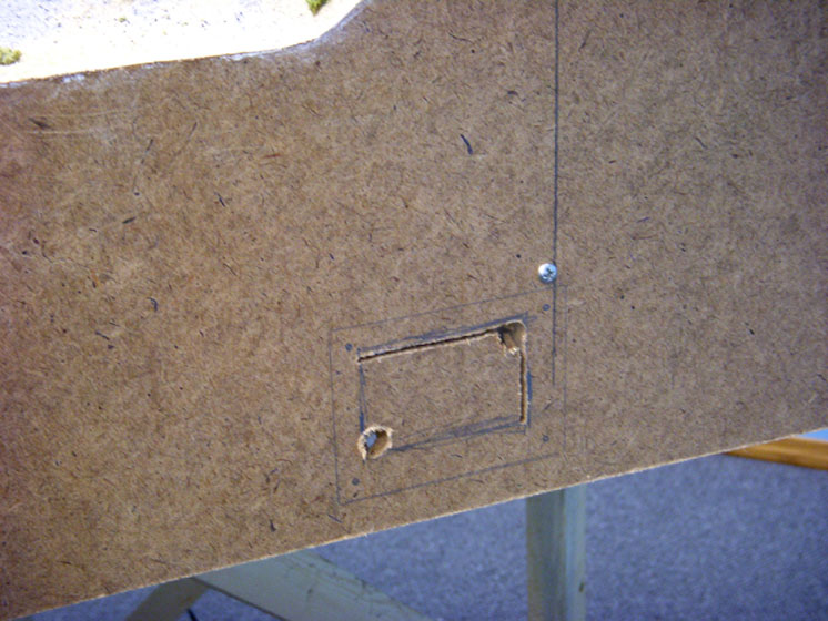
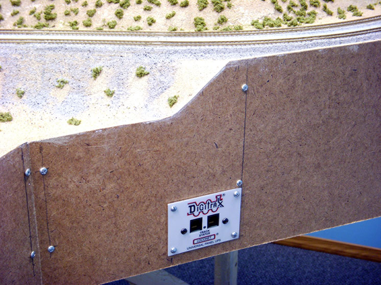
So, I found a spot on the angled fascia of the Meadow Valley Wash side that wouldn’t interfere with the retractable legs. Using the faceplate of the Digitrax plug-in panel as a template, I made pencil marks where the screw holes would be. See Fig. 8. Then I placed the plug module against the fascia and marked how large a hole I’d need to fit the plugs through. I drilled ¼” corner holes and used a keyhole saw to cut the center opening. Since there was nothing solid enough behind the fascia to hold any screws, I drilled holes through the fascia for small bolts that I used to secure the faceplate.
Next, holding the plug module in place from behind the fascia, I positioned the faceplate, inserted the fasteners, and tightened them down as seen in fig. 9. All that was left was to connect a cable from the command station to the remote plug-in unit, shown in fig. 10.
For the remote station at the other end of the yard, I simply followed the same steps. After painting the fascia I attached a strip of hook-and-loop fasteners to the fascia and its matching tape to the back of the handheld controller. The layout was ready to run.
The photo of the layout on its side in fig. 6 shows that the basic wiring isn’t what I’d call pretty. But it’s effective, it’s labeled, and it works. Phew!
Next time I’ll begin adding the desert scenery on the Meadow Valley Wash side of the layout.