In model railroading there are times where you may need a power reversing switch. A couple of examples are when you’re installing switch motors or adding a reverse loop to a direct-current layout. In this article, I’ll walk you through the steps of wiring a DPDT power reversing switch.
What is a DPDT switch?
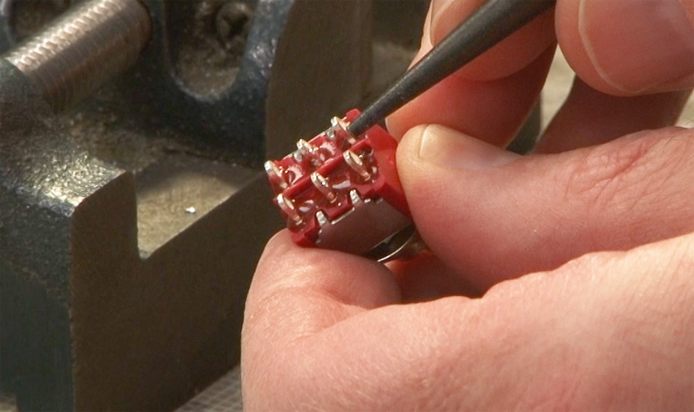
For this project I used a Miniatronics No. 36-250-08 DPDT switch. The ¼”-diameter switch (5 amp, 120V) has two rows of three poles on the back. The solder lugs have a loop in the middle for attaching wire and adding solder.
The center poles connect to the item that’s being wired, whether it’s a piece of track, a reverse loop, or a switch motor. The corner poles are the input points where power comes into the switch. You can reverse all of that and have the power come in from the center poles and go out to two separate things from the corner poles.
The throw part of the name means the toggle switch has two positions. The position of the switch determines which poles are energized.
Before wiring the switch for this project, I removed the hardware (two nuts and two washers) from the threaded bushing mount. You can attach this DPDT switch in anything up to 3/16”-thick tempered hardboard. It can also be installed in plastic, steel, and other materials, hence the various mounting hardware.
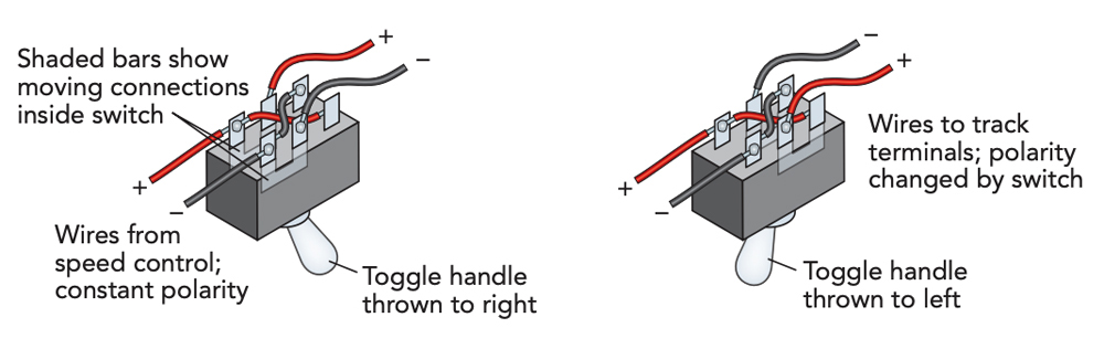
Cross the poles
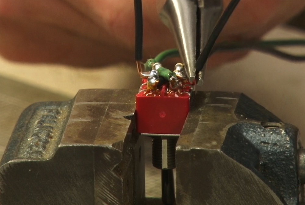
With the mounting hardware removed, I placed the switch poles up in a small vise. Don’t over-tighten the vise or you may break the plastic casing or damage the mechanism.
To make the power reversing switch, you need to bring power into one set of poles and cross it over to the other. Then, when the switch is set in the opposite direction, it reverses the plus and minus. Here’s how to do it.
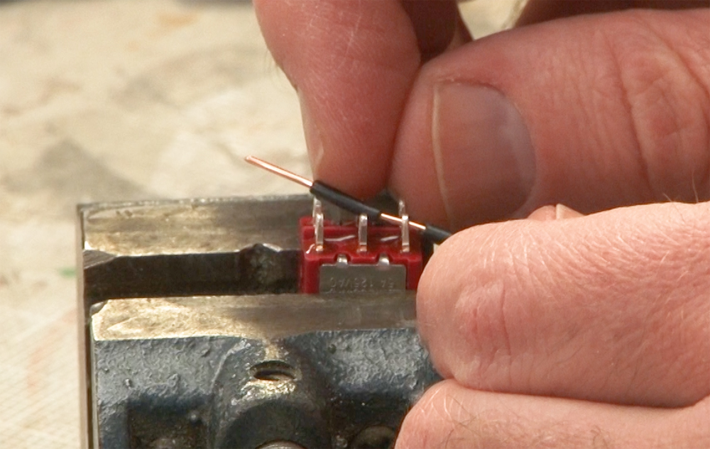
First, I used wire strippers to remove the black plastic casing from a pieces of 22AWG solid wire. I took off more casing than I would for a traditional connection so I could get between the poles on the diagonal. I gently slid the casing off the wire and set it aside. Then I slipped the wire through the hole in the solder lug.
Once I had the wire in roughly the position it would be, I put some casing back on the wire. This prevents it from shorting out the other poles and the other cross wire. You can use heat-shrink tubing instead of the wire’s original plastic casing for this step.
Next, I ran the black wire through to the diagonal opposite solder lug. I used a pair of needlenose pliers to bend the wire up and trimmed off the excess with wire cutters.
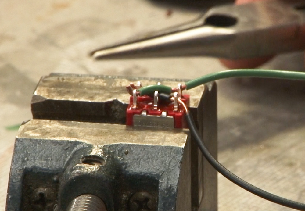
I then stripped the green plastic casing off the second wire, gently removed it, and set it aside. Then I slid the wire through the diagonal opposite pole and reinstalled a short length of casing where the green wire crossed over the black wire. I bent the wire up and trimmed off the excess.
Soldering the crossed wires
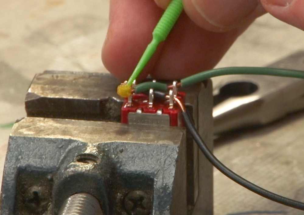
I used a regular Microbrush to apply liquid flux to the corner poles. When heated, the flux burns off the impurities, allowing the solder to adhere better to the wire and solder lugs.
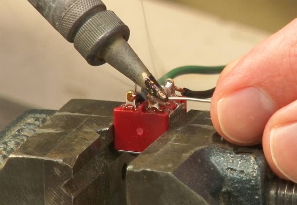
I used a pencil tip 35 watt soldering iron to apply the solder. I set the tip into the work and flowed the solder in. The solder should by shiny once it cools. If it’s dull and gray that means you have a cold joint.
One other word of caution. Don’t keep the soldering iron on the lugs longer than necessary or the plastic parts of the switch may melt. If you accidently overheat a pole and it sags a little or the plastic housing melts, throw the switch out and get a new one.
Make the center connections
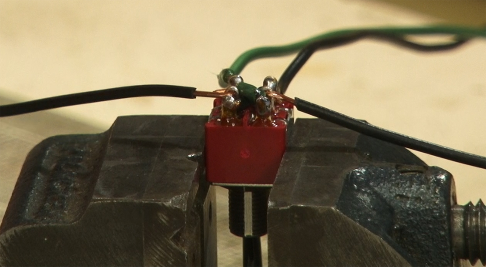
Finally, I attached the wires to the center poles. These are the wires that will go to the switch motor for my project. If you are working a reverse loop, these are the wires that go to the reversing section of track.
I used black wire for the center poles because I have green and black wires going into the DPDT switch. However, depending on how the switch is set, half the time that isn’t going to be correct. Using two wires that are the same color let me know they could be either polarity.
After I stripped the wires, I bent a hook into the end of each one with needlenose pliers. Then I hooked the wires into the solder lugs and crimped the ends with the pliers. I laid the wires out to the sides in preparation for soldering.
As before, I applied liquid flux to the middle solder lugs and used the same pencil-tip iron to apply the solder. I let the solder cool and checked the joints. Then, using needlenose pliers, I bent the wires into their final position for installation on the layout.
Test the switch function
Once I finished soldering the wires, I tested the switch. If I’d damaged any of the poles while attaching the wires, the switch wouldn’t flip right. It should toggle firmly in both directions, which it did. I also tested the electrical continuity of all poles using a multi-meter.
Though wiring a DPDT power reversing switch may sound complicated, it’s not that difficult if you follow these steps. Though this one was installed in our Thin Branch project layout, you can make one of these for pretty much anything that you need to reverse the polarity on for your model railroad.