When I first got into model railroading, I tried handlaying my own track and quickly discovered that it wasn’t that hard. One benefit is that buying rail, spikes, and ties in bulk is considerably cheaper than purchasing ready-made track. Handlaying also lets me to duplicate unusual track arrangements found on full-size railroads. In addition, it allowed me to try my hand at scratchbuilding a lift-frog turnout.
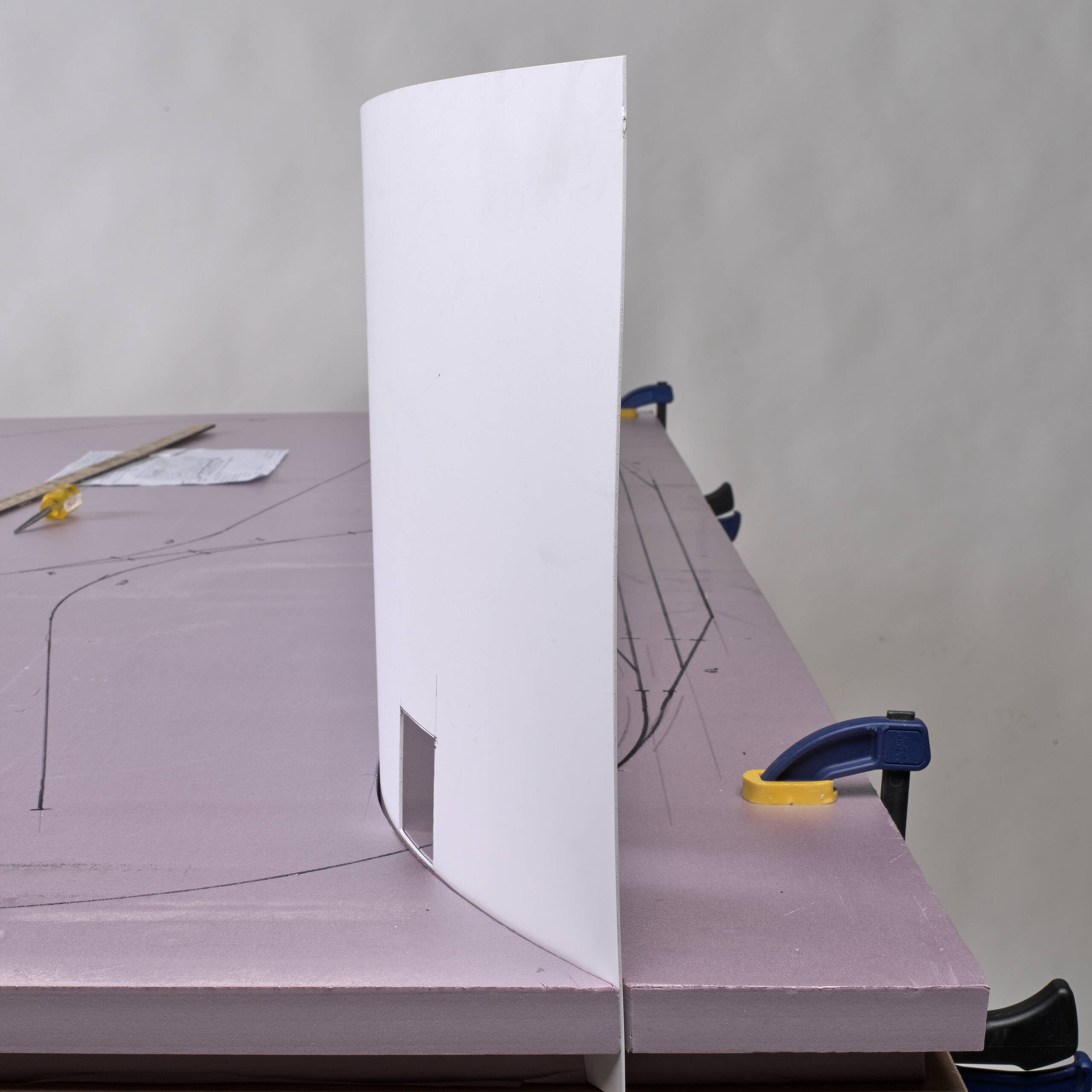
Several years ago, I experimented with building a McPherson switch, an interesting turnout where the mainline is uninterrupted and the diverging track is elevated a few inches and crosses over the main by means of a movable, elevated frog segment. I went as far as constructing a mock-up of the turnout before concluding that although I could build it, the linkage mechanism was more complex than I wanted to deal with.
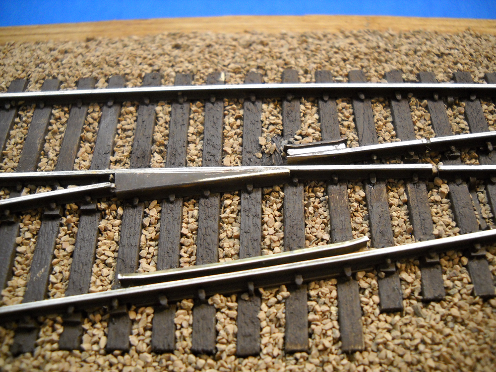
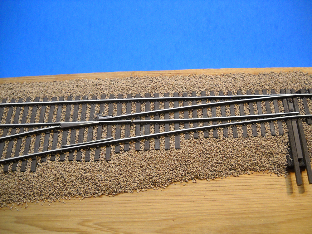
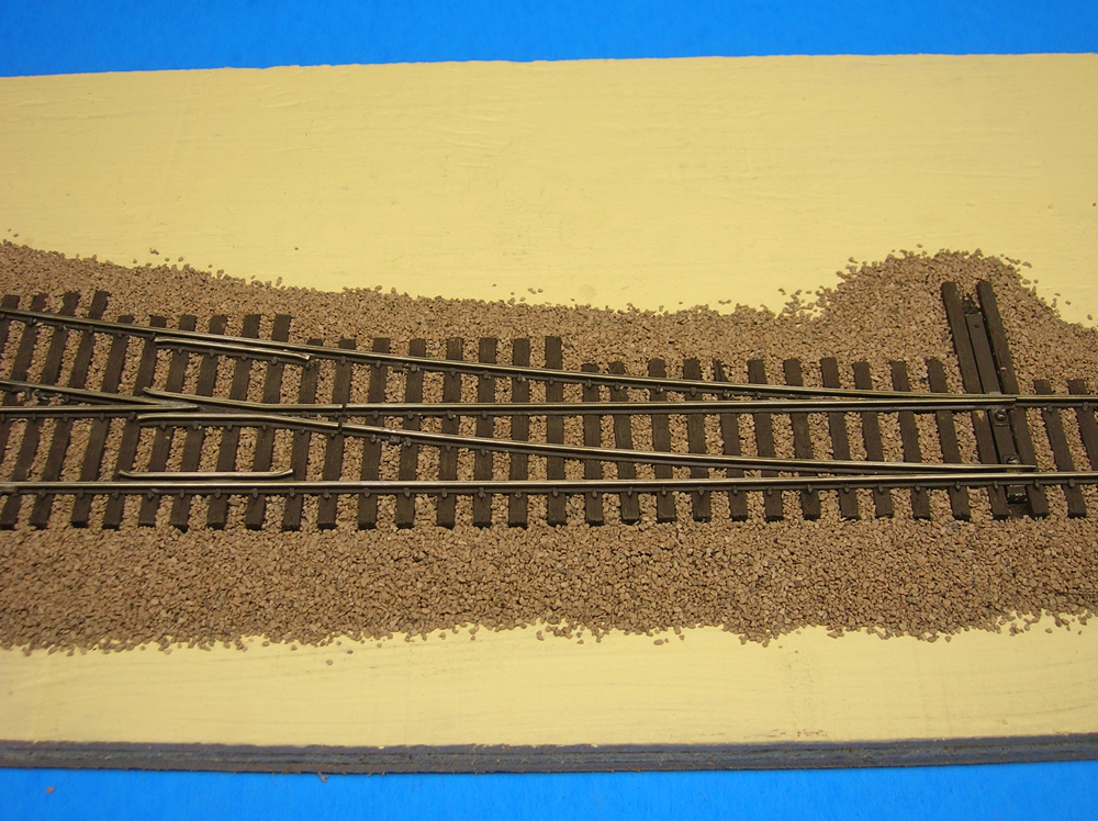
Then, while perusing the April 2022 issue of Model Railroader magazine, I noticed a piece on lift-frogs in the “Ask MR” section. That looked interesting, because it accomplished the same thing as a McPherson switch but with a lot less complexity. After some additional internet research, I decided to build one. The finished result is shown in the photo above.
If you’re interested in building a lift-frog turnout so you can display an interesting bit of craftsmanship on your layout, or if you’d like to learn more about handlaying turnouts in general, read on and give these techniques a try.
Laying the rails
I like to build the major parts of a turnout on my workbench and then transfer the finished components to the layout. Since one of the great advantages of handlaying track is the flexibility it allows in layout design, each turnout is pretty much a custom fit for a specific location.
As a result, I first do a combination of measuring and eyeballing to determine the angle of the frog (the frog number) and the distance between frog and the points. The idea is to create a smooth flow of the rails through the turnout and its connected trackwork.
After constructing the turnout on the workbench, there’s usually some tweaking required when installing the finished components. However, with careful preparation, the amount of tweaking is usually minimal.
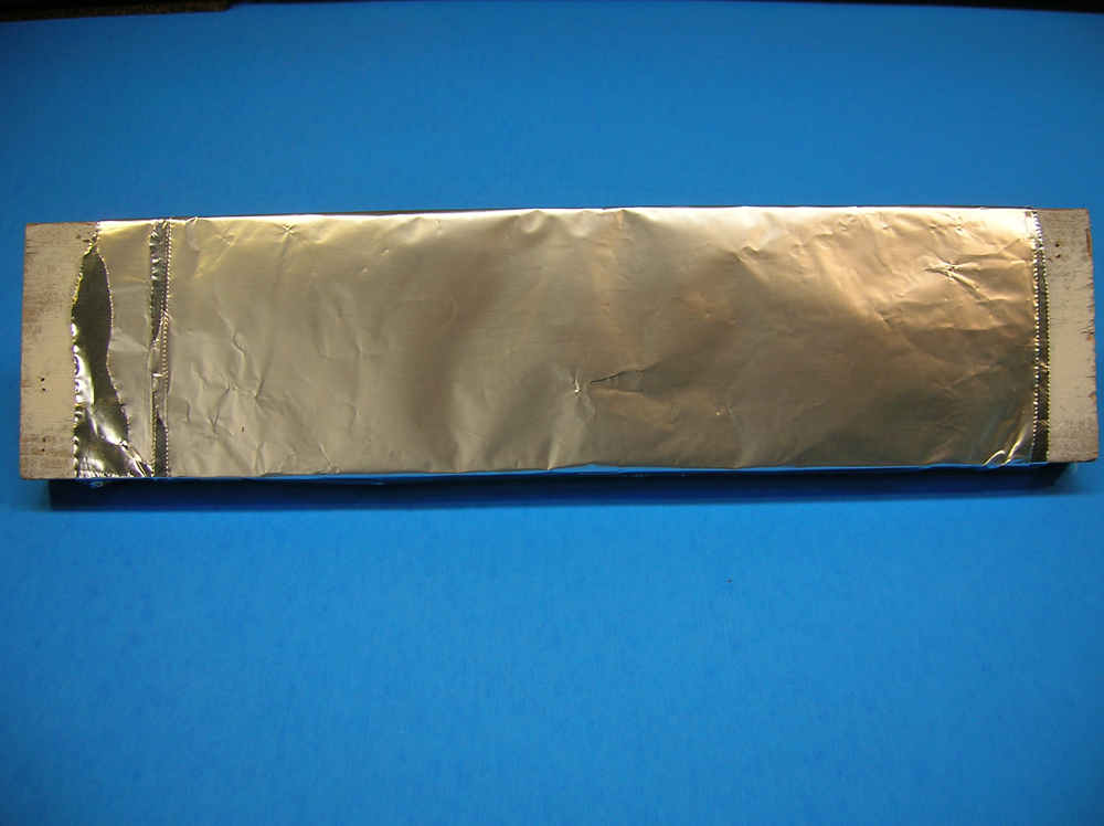
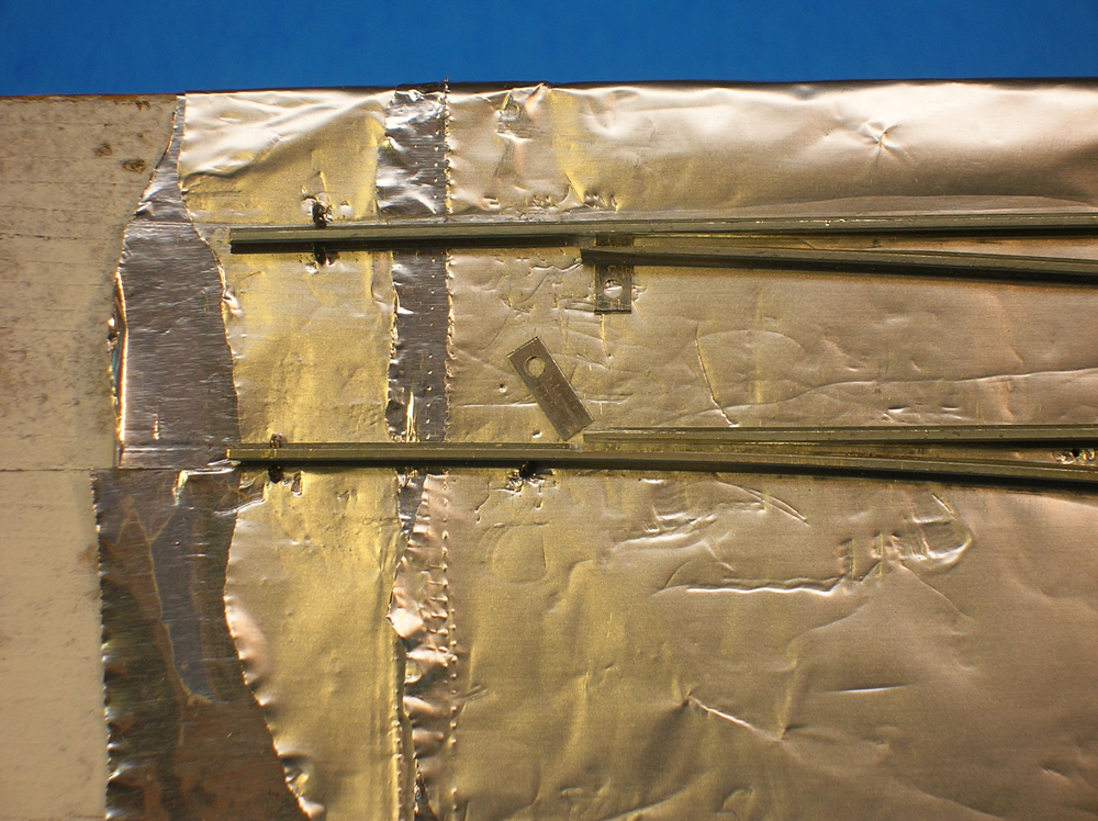
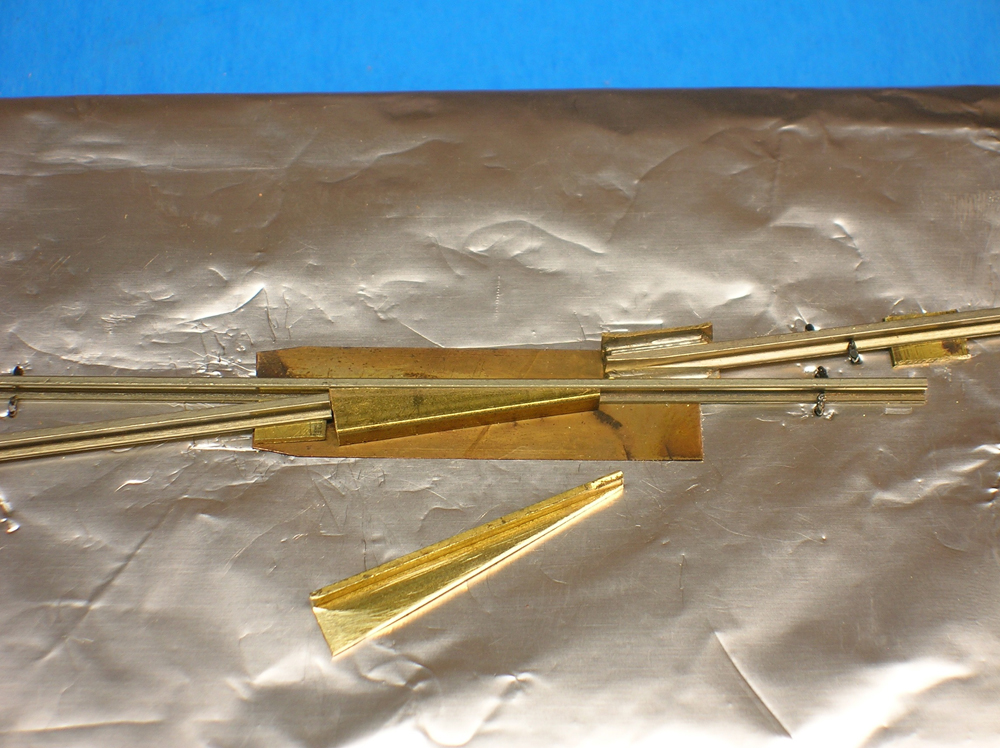
To get started, I select a piece of 1 x 4 softwood and cover it with four layers of aluminum foil. The wood lets me to easily spike the rails into position, while the four layers of foil protect the wood from the heat of soldering the components together opposite.
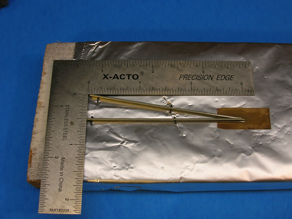
The first pieces of rail to go down are the frog rails. Then I add the stock rails.
Next are the closure rails, which run uninterrupted from the switch point through the frog. Later I’ll cut a gap in these rails.
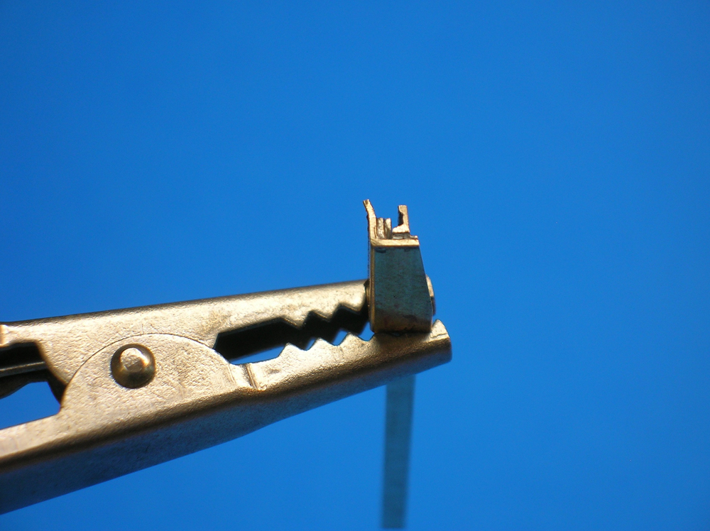
I then shape the curved point/closure rail on the diverging route. There are no hinges between the points and closure rails. I notch the point rails so they seat tight against the stock rails.
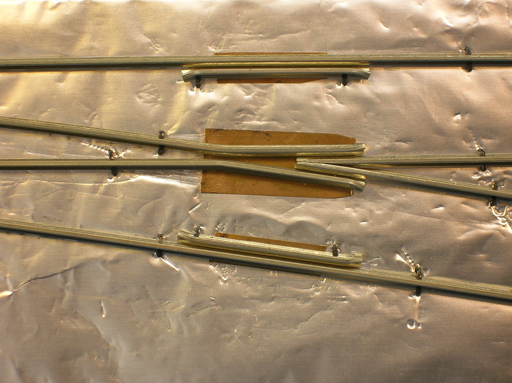
After that I soldered metal tabs with screw holes under the point rails for later attaching the switch rod.
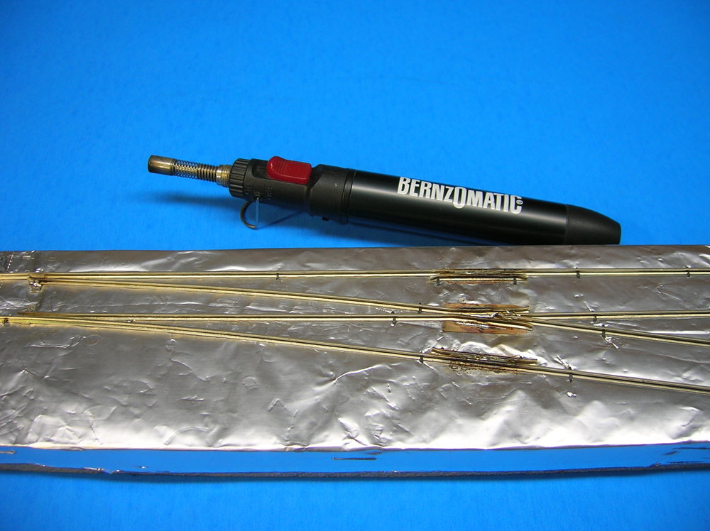
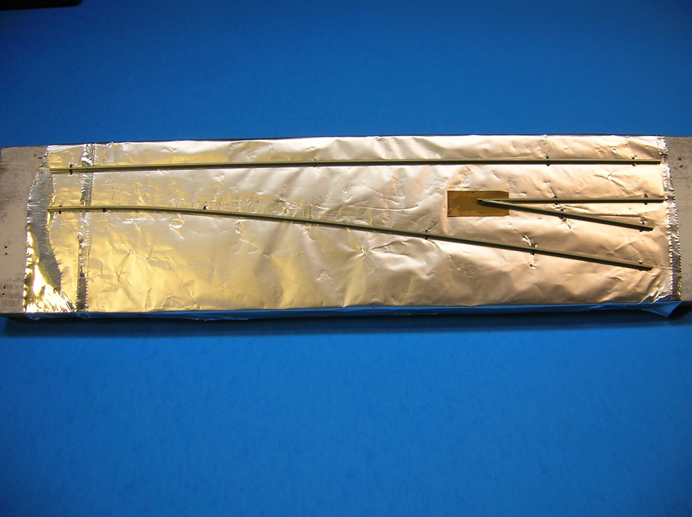
After fitting the turnout components together and spiking the parts down on the foil-covered board, I use a small propane torch to solder everything together. The foil dissipates the heat from the torch.
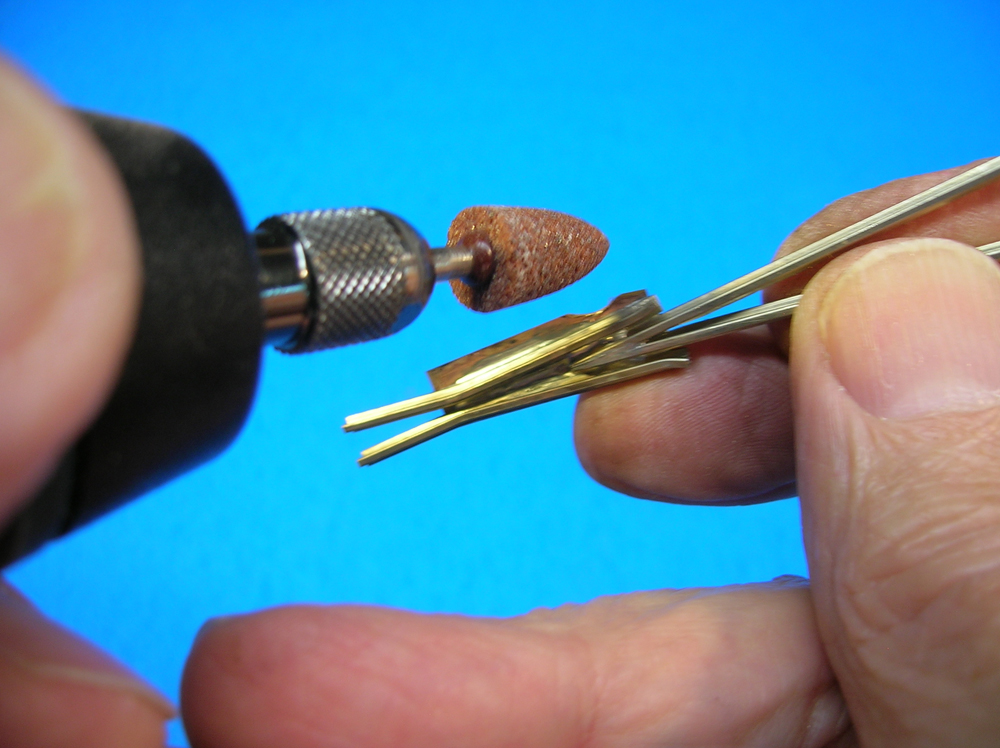
The finished parts are then removed from the board. Then I remove the flux and stray solder and trim the excess shim brass from under the frog and guardrails. The point/closure rails are also detached from the frog to be installed separately, since they must be electrically isolated.
Installation
The turnout components are now moved to their location on the layout and spiked down. A National Model Railroad Association standards gauge is used to make sure everything is aligned properly. The point/closure rails are spiked in position. Leaving enough play in the turnout to permit any final adjustments. Bits of styrene are used to insulate the gaps between the closure rails and the frog.
Jumper wires are then soldered between the frog rails and their adjacent stock rails. This, and the lack of a joint between points and closure rails, eliminates dependence on the points contacting the stock rails to maintain electrical continuity.
Next, a styrene switch rod is installed beneath the points. Screws are used to secure it to the metal tabs.
I cut my own crossties from wood paint stir sticks, available for free or inexpensively from any hardware store. I glued the ties to the roadbed and spiked down the rail before painting them, especially if the rail is bare.
Once the feeder wires are attached to the frog and the stock rails, I spray the rails and ties with Floquil Roof Brown. [Floquil paints were discontinued by Testor Corp. Solvent-based paints are available from other companies. – Ed.] This gives everything, including the spike heads, a rusty brown appearance. Stains and/or paint can be applied to the ties later on if you want to give them a weathered look.
After the paint on the railheads is cleaned off and the switch machine or ground throw of your choice is installed, your turnout is complete.
The lift-frog
Making a lift-frog turnout largely follows the same process as laid out above, but a few modifications are necessary. In the case of the lift-frog turnout, the first pieces of rail to go down are the stock rails. They’re notched for the point rails and spiked down.
Next came the inside mainline closure rail, which runs uninterrupted from the switch point, through the frog area, to beyond the end of the turnout.
After that, the diverging route closure rail is shaped, curving from the switch point to a location where the wheels on the mainline can just run past it without fouling. I then cut a piece of rail for the inside half of the diverging route beyond the frog, arranging it so the outside edge of wheels passing on the main won’t hit it.
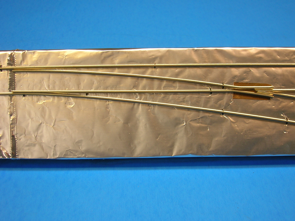
The diverging route has to be elevated .025″ at the point where it crosses the mainline rail. This is the depth of the flange on an RP-25 wheel. With this arrangement, as the wheel approaches the frog, it leaves the railhead and runs on its flange. It then crosses the mainline rail on its flange before being lowered on the other side of the frog until the tread meets the railhead again. The short elevation of .025″ for the diverging route is gentle enough to allow this to happen smoothly.
The frog components, with the rail height difference accounted for, are then soldered to a .005″ brass shim. This means shims gradually increasing to .030″ thick under the diverging route rails approaching the frog are necessary to give the desired .025″ difference between the mainline and diverging railheads. The diverging rail must be precisely .025″ higher where it crosses the main.
Preventing derailments
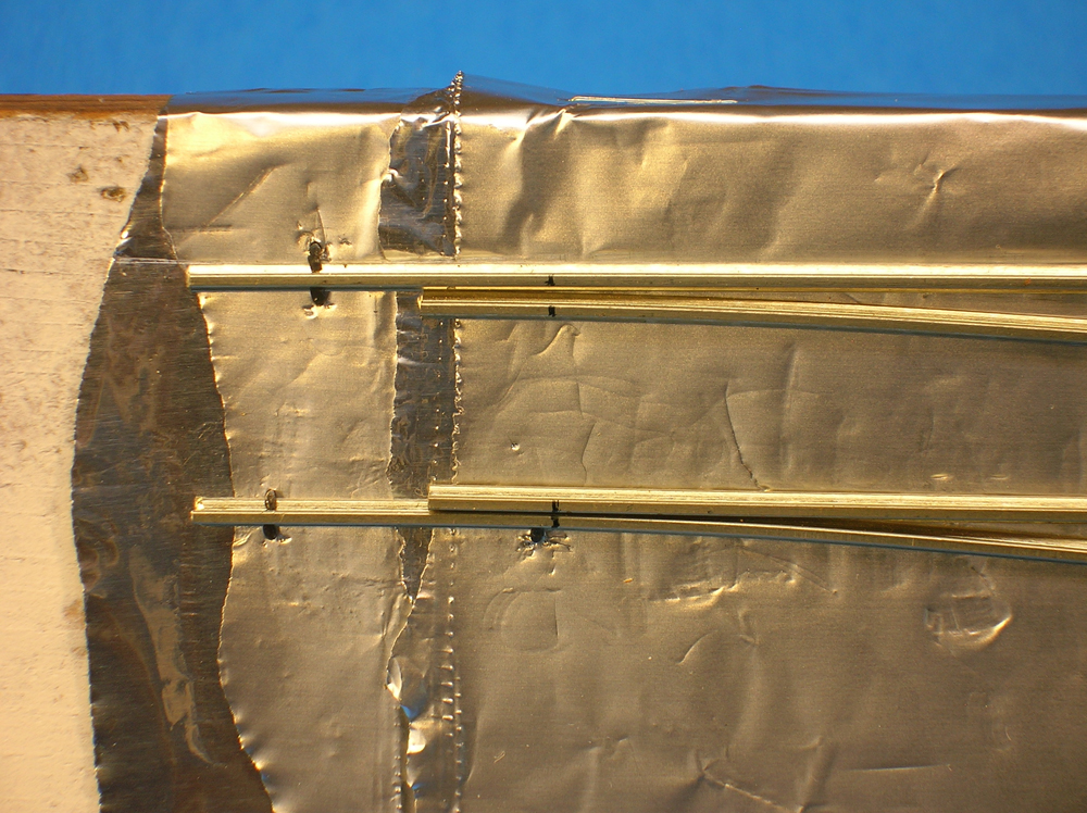
Both elevated diverging route rails approaching the frog have to be far enough away from the mainline rail to prevent fouling by passing wheels. This gap will be wider on a model than on the prototype because model wheels and flangeways are oversized. This means there’s a gap that has to be filled at mainline railhead height so the wheels on the diverging route can cross the main on their flanges without dropping into the void.
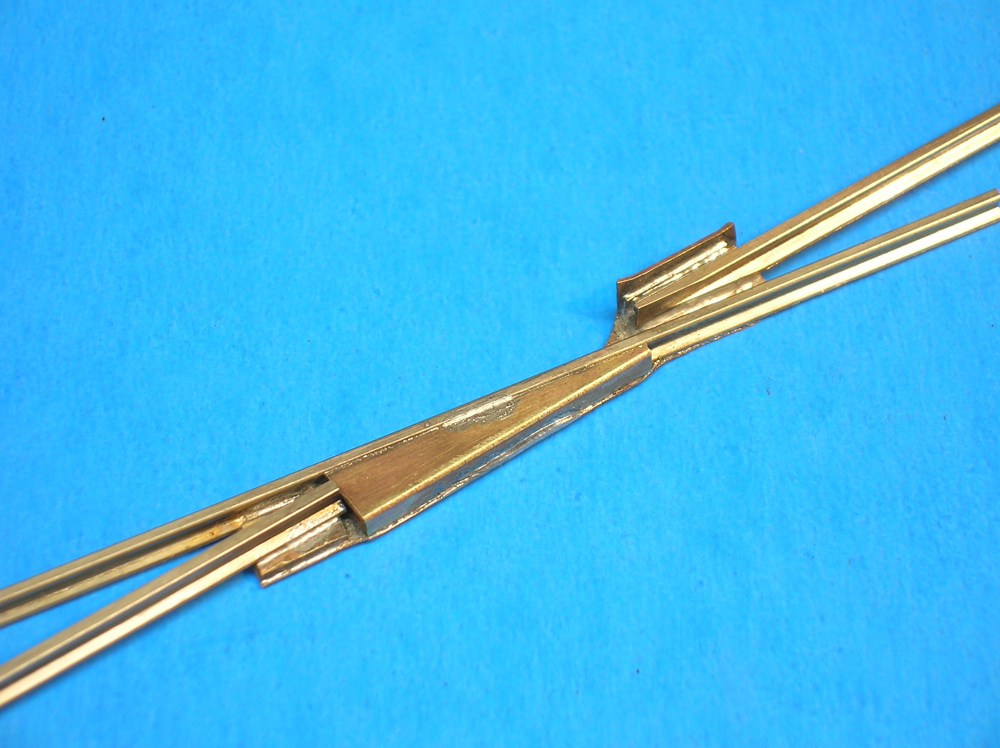
I filled the gap with an appropriate length of brass channel .250″ wide and .083″ deep (for code 83 rail). The channel was cut diagonally, and half of it was soldered against the outside of the mainline rail.
On the other side of the main line, solder a piece of brass angle on the outside of the diverging rail in a position that helps guide the outside of a passing wheel in order to keep the flange from crowding against the railhead.