Turnout motors always seemed a bit pricey to me until I learned about servos from a friend who’s a radio control (RC) enthusiast. He uses servos in his aircraft, and they sell for less than $10 each. The “servo” name is a contraction of the term “servomechanism.” These devices use a lightweight can motor to drive a high-ratio gearbox that operates a model aircraft’s flaps and other control surfaces.
This information started my search for servos that eventually led me to the Tower Hobbies website at www.towerhobbies.com. Tower sells the single Hitec model no. HS-311 servo for $7.99 each. If purchased in groups of three for $23.10, the price drops to $7.70 each (special stock number LM3129).
Even if I add a pair of Omron no. 187709 SPDT microswitches (Jameco) to each installation for frog power and signalling, the unit cost remains just slightly over $10 each.
Servo modification
For my use, all I needed was the servo’s DC motor and its matching gearbox. Each servo also includes a printed-circuit (PC) board that’s part of its RC electronics, a three-wire cord, and a plug, which I remove and discard.
I begin modifying the servo by applying a piece of masking tape across the top front of the servo and part way down both sides to secure the faceplate to the case. If you omit this step, removing the four screws from the case allows the entire thing to come apart and you’ll have a handful of little gears.
Next, I flip the servo over so the output shaft faces down and the three wires and plug are at the top. (A Panavise or similar clamping device with nylon jaws is helpful here as a third hand.) I remove the four long screws that hold the servo case together.
Once the case is open, the servo’s motor is at the top with the three-color cable next to it. I carefully remove the PC board and the RC electronic components by unsoldering the board from the motor terminals. Once the board is free, I cut the wires attached to the PC board, and tuck the rest down into the case alongside the motor.
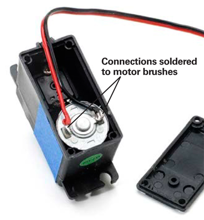
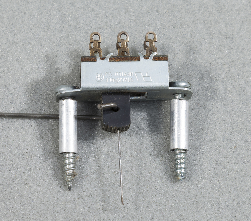
I cut off the connector plug from the wire cable and carefully separate and strip off the yellow wire from the others. I then solder the red wire directly to the right motor terminal, and the black wire to the left terminal as shown in fig. 1. This gives me a DC motor free of electronics with two wires (red and black) coming off the motor terminals. Then I reassemble the case.
Mounting the servo
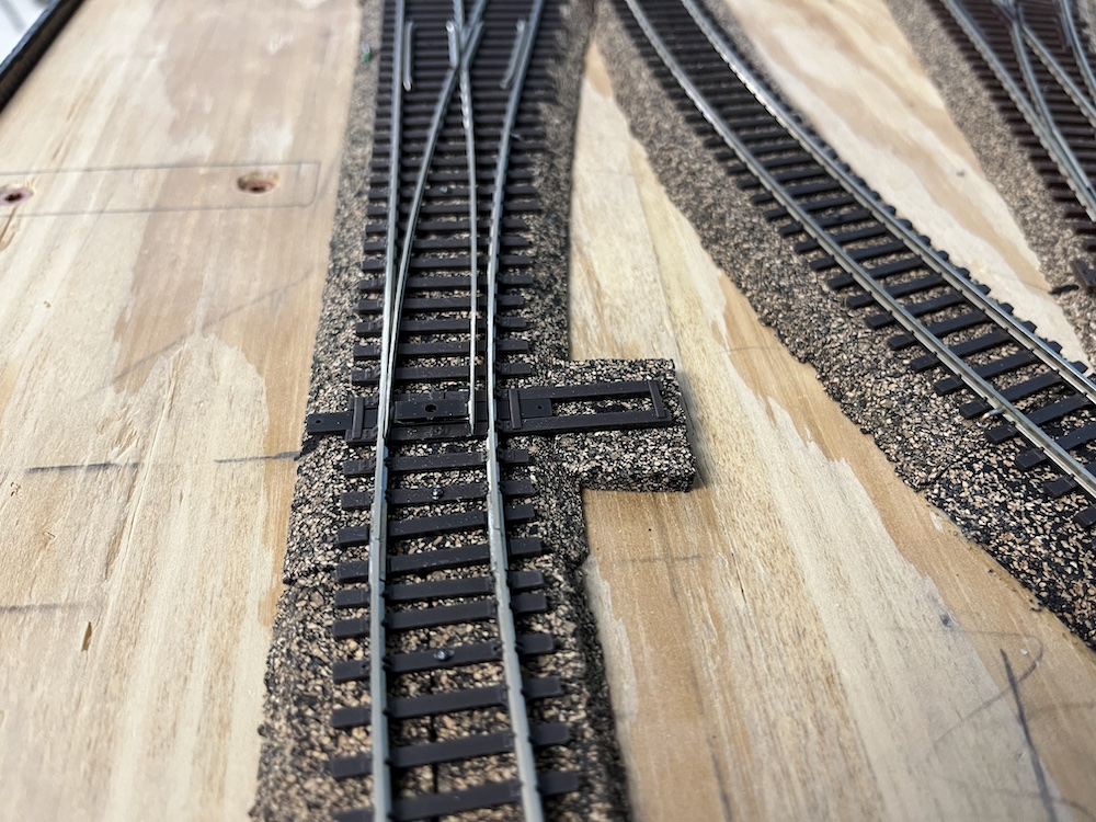
I center the switch points in their mid-throw position, mark the spot on the layout with an awl, and then drill a ¼” hole through the benchwork. A pair of HO switch points normally moves about 1⁄8″, so the ¼” hole works fine.
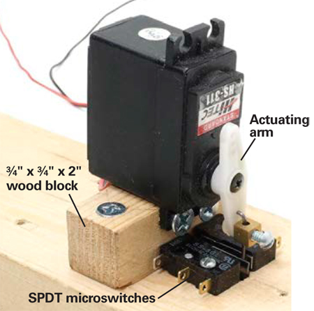
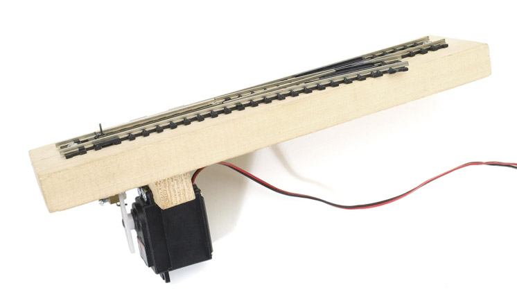
I mount the servo motors under the turnouts on ¾” square blocks of wood, 2″ long, as shown in fig. 2. The servo is centered on the block and secured with a pair of no. 6 x 3⁄8″ panhead screws.
An actuating wire must be added to connect the servo to the turnout’s switch rod. Each servo includes an assortment of plastic arms and wheels that have 1⁄16″ diameter holes for push rods and grooves that match the splines in the servo’s drive shaft. I use a short length of K&S .039″ or .047″ piano wire, bent to fit into the holes in an arm, to convert the servo’s rotary motion into the linear motion that moves the switch points.
Great Planes sells connecting hardware to attach the piano wire to the plastic arms. However, I found the small Allen screws supplied with the connecting rod hardware won’t clamp down on .047″ piano wire. Instead, I use 1⁄2″ 4-40 steel screws that will easily cut threads clear to the bottom of the hole in the brass block so I can tighten them down.
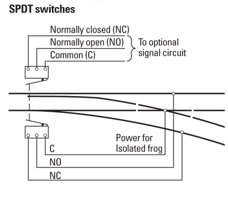
I mount the servo under the switch points so its actuating wire is centered in the ¼” hole and extends up through the switch rod. I also add a microswitch on each side of the actuating wire to power the frog and operate signals. See fig. 2.
Servo operation
Servos will operate on either a single DC power supply or a bipolar supply delivering +12VDC and -12VDC. The bipolar supply allows you to use single-pole double-throw (SPDT) toggles to simplify the turnout control wiring.
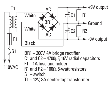
I use a 12V center-tap transformer to produce positive and negative 9V, as shown in fig. 3. Each motor draws 80mA of current, so under an 80 percent load factor, a 3A transformer should handle 25 to 30 motorized turnouts.
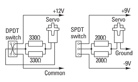
Servos in RC models normally operate on 4.5V to 6V battery packs, so I had to include dropping resistors in the control circuit to reduce the voltage to run the motors. For a 12V power supply, use two 330Ω ½-watt resistors in parallel; for 9V use 200Ω resistors. The wiring diagrams in fig. 4 show both 9V and 12V versions of the control circuits.
Avoiding point drift
The servo gearboxes resist turning by hand, but that’s a bad practice anyway. The gears seem stiff enough, and may hold the switch points in position without a constant application of power.
However, I’ve found that unpowered motors tend to drift open under gentle pressure. The microswitches I use for additional contacts may also cause some drifting because their internal springs have enough pressure to gradually move the points.
To avoid this problem, I use regular toggle switches to control the turnouts so I can maintain constant power to the servos. In this stall mode, each servo motor draws about 66mA of current.
Overall, these servo motors are easy to modify and install. And considering the minimal motion they need to make, the servos’ life expectancy on a model railroad is practically unlimited.
Sources
All Electronics Corp.
(Resistors, toggle switches)
www.allelectronics.com
800-826-5432
Jameco Electronics
(Microswitches, toggle switches)
www.jameco.com
800-831-4242
Tower Hobbies Inc.
(Servos, Great Planes hardware)
www.towerhobbies.com
800-637-4989 (orders only)
800-637-6050 (order assistance