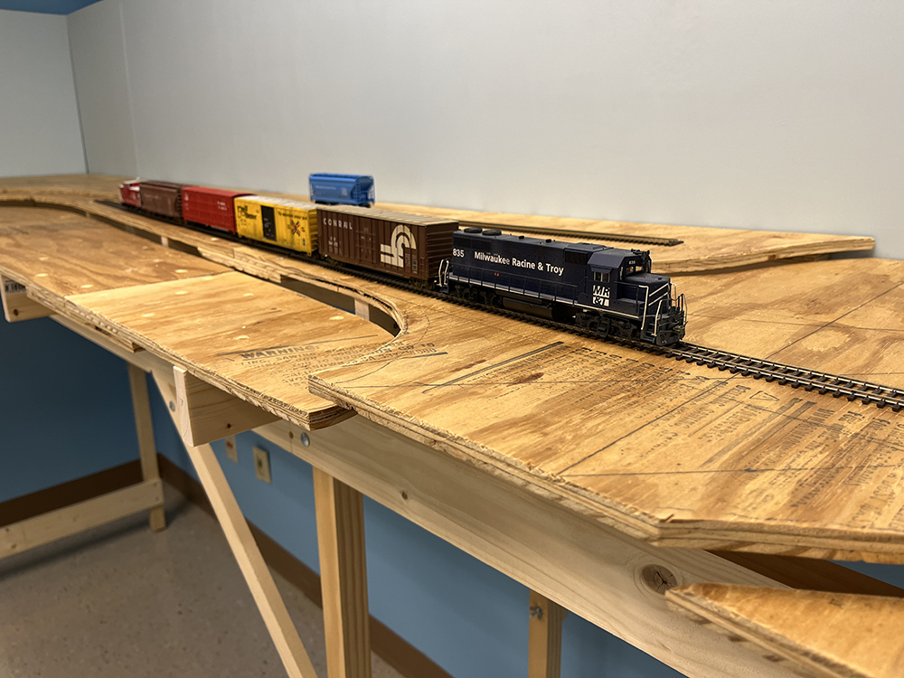
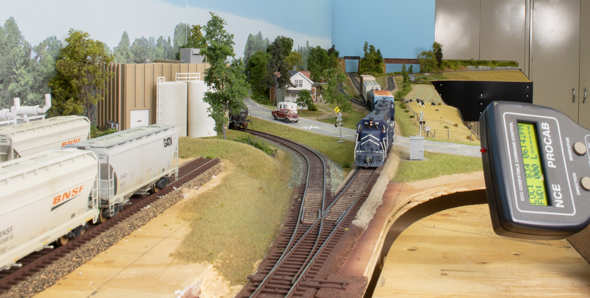
There’s nothing quite like that feeling of running a “first train” on a new model railroad. Although the scenery is still bare benchwork, the look and sound of those first wheels rolling under their own power along nickel-silver rails produces a thrill that never gets old. By the time we reach the conclusion of this three-installment article series covering the East Troy Industrial Park HO scale project railroad, we will be able to do just that – run some trains!
In case you missed the previous installments in this series, our East Troy layout is an extension of the Milwaukee, Racine & Troy RR built by the Model Railroader staff. It depicts a modern railroad operating over a stretch of former interurban track now owned by the East Troy Railroad Museum to reach several customers grouped into an industrial park. The industries are rail-served, and they represent real-life counterparts found in Southeastern Wisconsin and along the SMS Rail Lines Purelands development in New Jersey.
To lay the track and power the rails, we used tried-and-true products, such as flextrack and cork roadbed. However, we also experimented with some new materials as well, including Walthers foam roadbed. For control, we installed an NCE Digital Command Control system on the railroad, as well as Walthers switch machines. Both of these feature plug-and-play components, making them easy for modelers of all skill levels to install. For Trains.com members, you can watch video episodes of our East Troy series explaining every step of the projects shown here in greater detail on Trains.com Video.
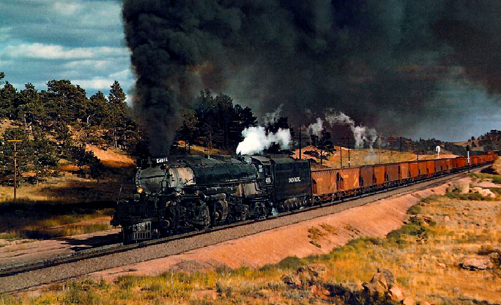
Before we get started, however, many readers have asked if we plan to string overhead wire on the layout. While we hope to install it one day to better represent the trolley museum, because of its delicate nature, we’re saving it as a future project.
Until then, let’s get started laying track on the East Troy!
Roadbed
Roadbed is that stuff the track sits on. On a real railroad, it’s made up of graded ground and several layers of crushed rock that not only serves to lock the track in place, but gives it some flexibility for expansion and contraction and allows for adequate drainage. On a model railroad, roadbed produces a level surface for laying track, as well as gives the right- of-way a more realistic profile. It also provides some sound-dampening qualities that help eliminate the noise of the train’s operation so you can better hear its sound system.
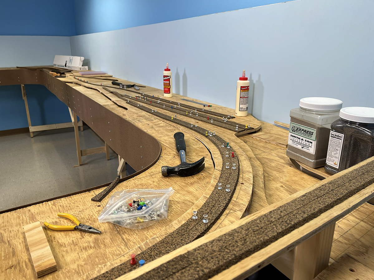
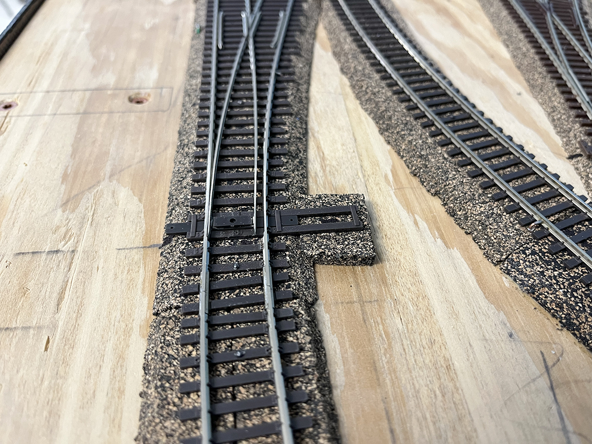
There are several roadbed options for modelers. We used cork strips, which are the most common. Our cork came from Midwest Products, and to save time cutting and fitting roadbed at turnouts, we also used a number of left- and right-hand cork turnout pads.
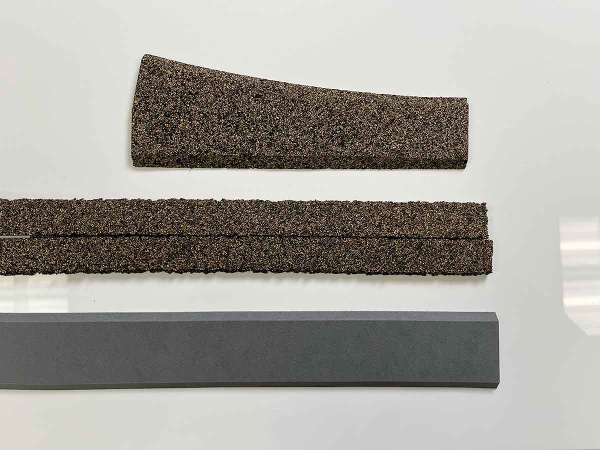
Cork roadbed is easy to use. Simply split the strips along the perforation down the middle, then position the two pieces with their beveled edges facing out along your track’s centerline marked on top of your subroadbed. You can use white glue or wood glue to attach the cork to the layout’s surface. We used push pins, carefully tapped into the plywood with a hammer to hold the strips in position on curves until the glue dried. When laying cork on foam surfaces, use an adhesive caulk, such as DAP Alex Plus. It produces a more elastic bond than wood glue can provide when securing the cork to the polystyrene’s surface.
One last step is to sand the cork’s beveled edge after the glue has dried. The edges will have leftover cork bits attached from the cutting process. It’s best to remove them with a coarse-grit sanding block before laying the track.
Track
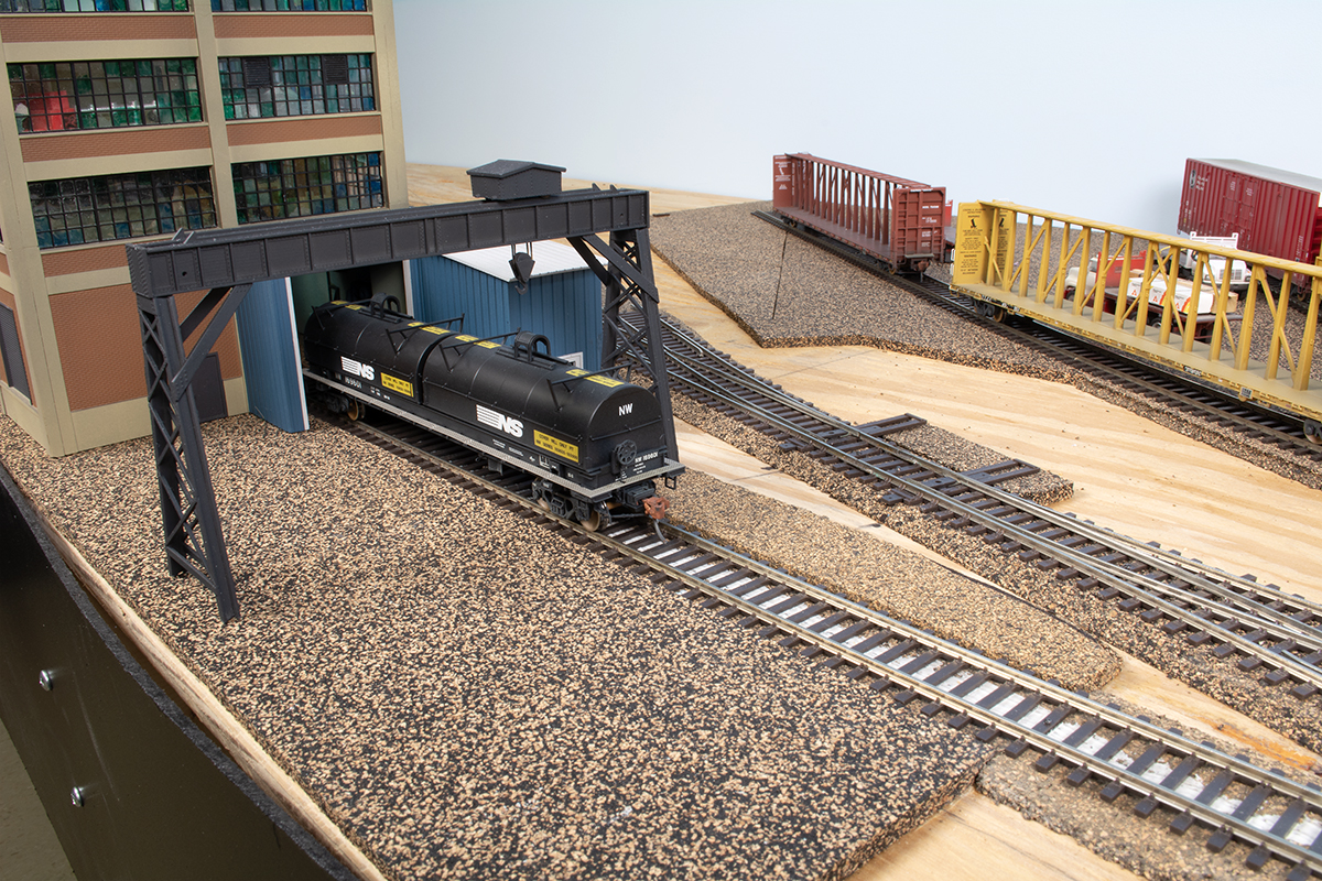
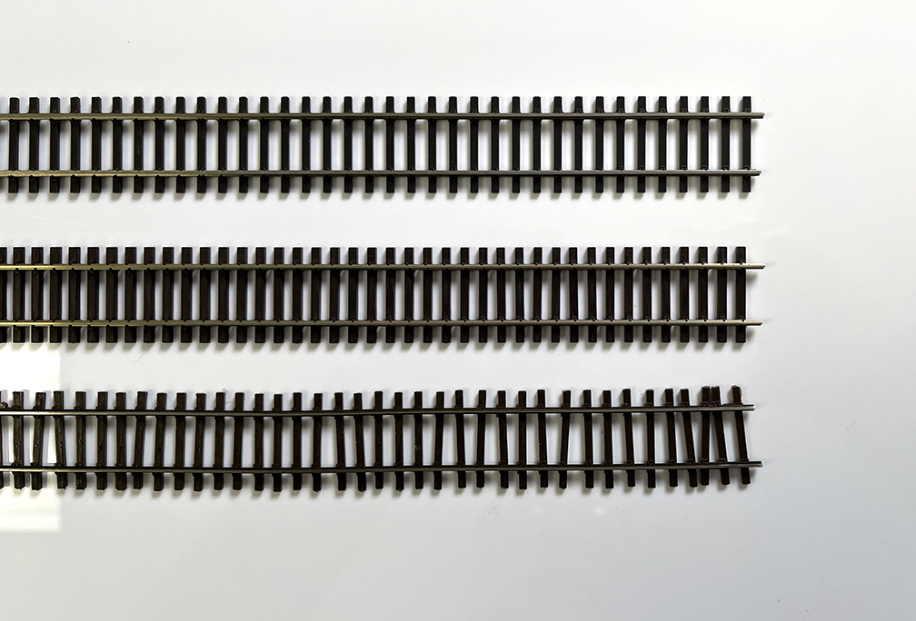
We used a combination of track components from several manufacturers for the East Troy layout. For most of the MR&T and trolley museum portions of the layout we used Walthers code 83 branchline track. This has a wider-spaced tie pattern, often found on lighter trackwork. For the Canadian National main line at Mukwonago we used Peco Streamline code 83 track. Its denser tie spacing mirrors what is found on Class 1 railroads. We also used a few pieces of Micro Engineering code 83 track on the plastics industrial spur, representing less-well maintained track.
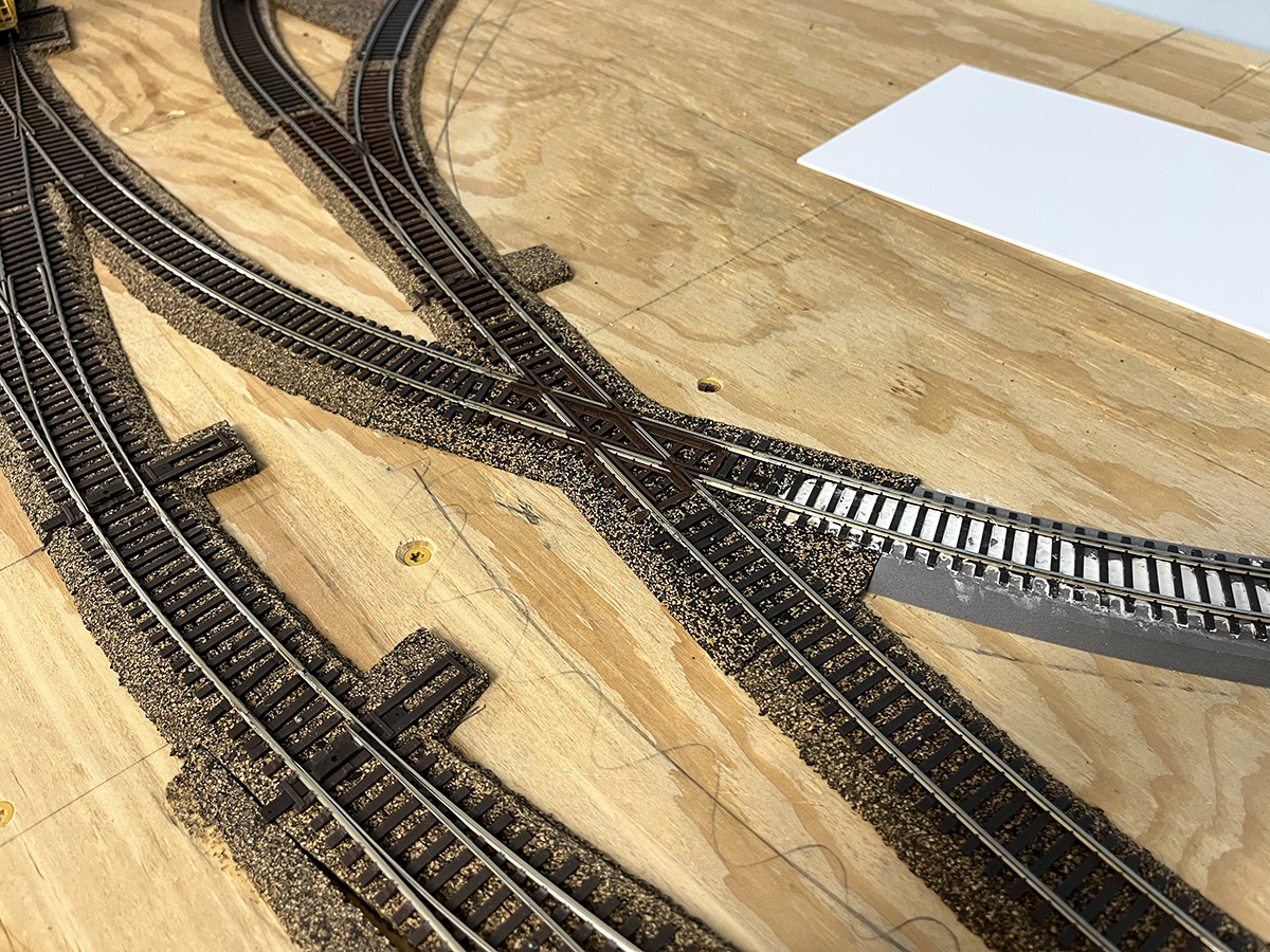
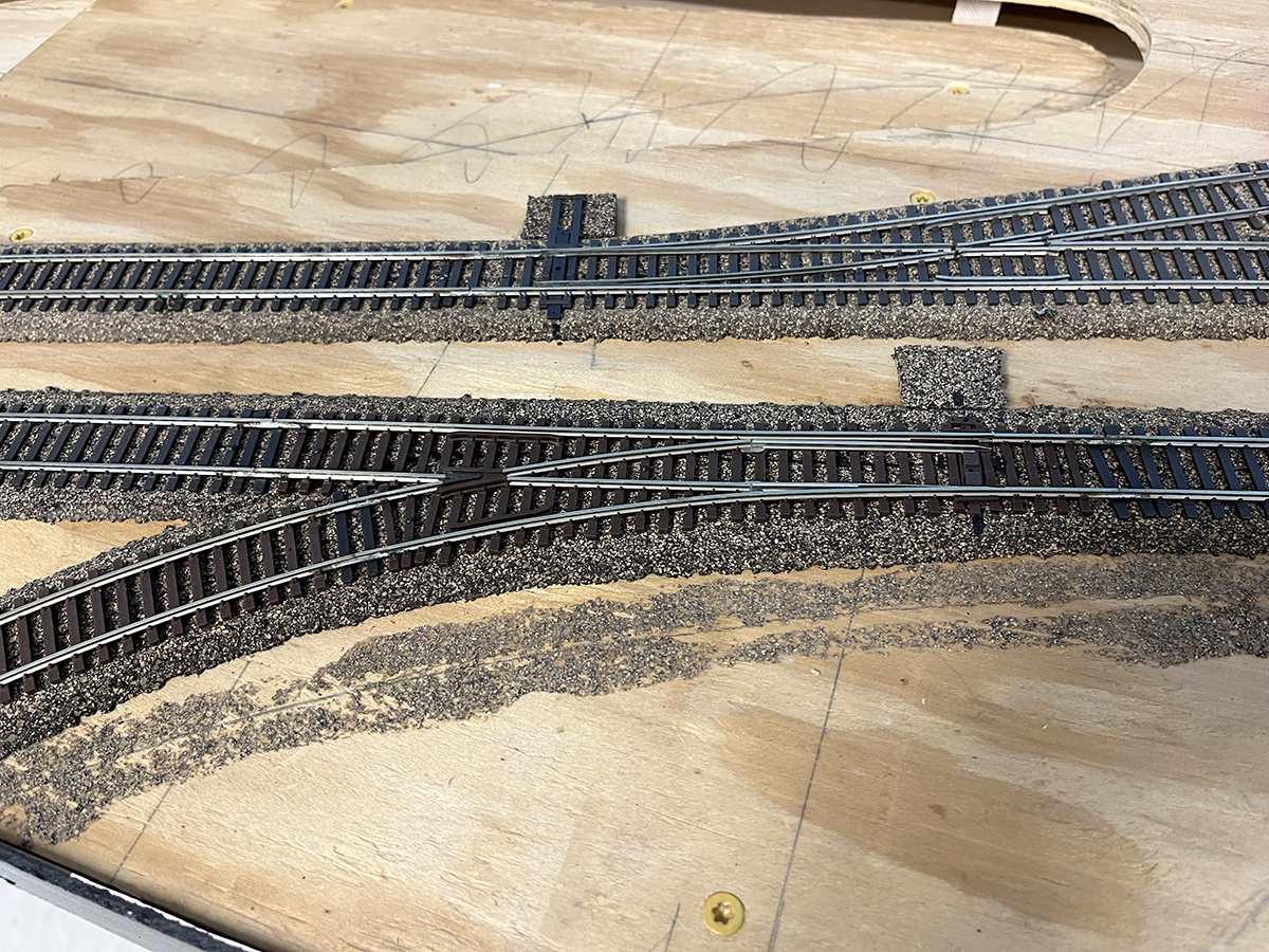
Most of the turnouts on the layout are Walthers code 83 no. 5s, with the exception of a no. 4 at the lead to the transload yard and a curved lefthand turnout entering the siding at East Troy. There are also two Atlas 18″ radius Snap-Switches. These have continuous radius frogs, and are useful where tight trackwork is needed. We used one Atlas code 83 30-degree crossing in East Troy as well.
Much of the flextrack is affixed to the layout with adhesive calk, particularly over the Walthers foam roadbed sections. We used Atlas track nails on the turnouts to keep the moving parts free of caulk. Nails allow you to reposition turnouts if needed, as well.
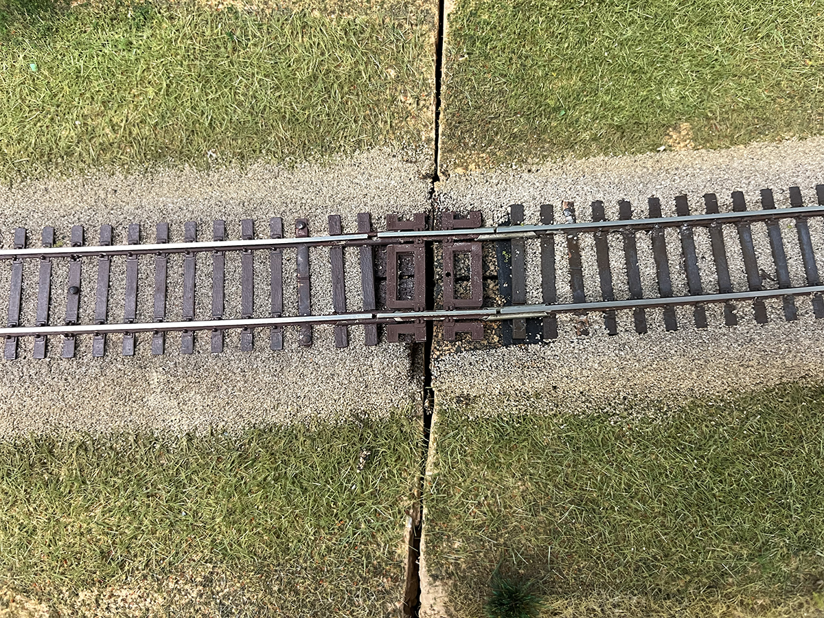
Since our layout splits into three separate sections, we used short Atlas code 83 “set track” fitter pieces at the joints. Unlike flextrack, set track has its rail fixed to the plastic ties, so it will never lose its alignment. Be aware that the ties on these pieces are thicker than any of the other track components used here, and so we had to sand the backs of the fitter pieces to thin their ties to the correct height to match the other track.
Wiring
Although this is a mid-sized model railroad, the East Troy layout will likely be operated by just one crew at a time. Therefore, we wired the layout as a single electrical block.
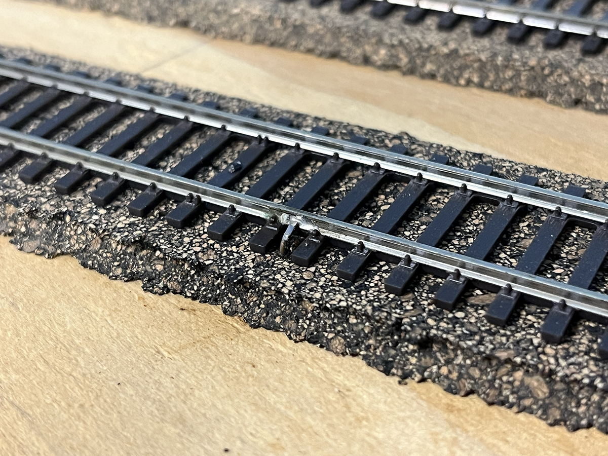
Every third section of track received 22 AWG feeder wires. The feeders were soldered to the web of the rails. If you are concerned about how this will look when the layout is finished, don’t be. After the track is painted and ballasted, you will be hard-pressed to spot the feeders without actively looking for them. Although we didn’t power the turnout frogs right away, we did attach feeders to those as well. The Walthers turnouts have a metal tab attached to the frog, making it easy to loop a wire through it and secure it with solder.
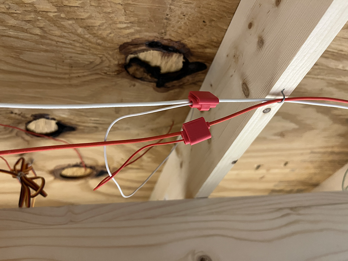
Under the layout, we ran a two-wire power bus, using 16 AWG wire. We attached the feeders to the bus using Scotchlok insulation displacement connectors (IDCs). Installing these is as easy as inserting the wires into the IDC, crimping the connection with slip-jaw pliers, and snapping the plastic compartment lid shut. IDCs are fast and eliminate the dangerous task of soldering any wires while you are under the layout. Associate editor Bryson Sleppy and I had all 33 feet of the layout wired in a single afternoon.
We’ll leave it there for this week, but be sure to check back in over the coming weeks for the next installments of this three-part series!
Click here to read the previous article in the East Troy Industrial Park series on Trains.com.
Share this article