


A helix – a spiral ramp meant to lift a model train from one level of a layout to another – may not be prototypical, but it’s still important to build it well. Only if it starts out right at the bottom can the rest of it function smoothly and reliably.
My helix was designed to move HO scale trains between three layout levels. The lowest is the “basement” staging yard, only about 22 inches up from the floor. The next is the lower deck, which is about 38 inches off the floor. Finally, the upper deck is close to 56 inches high.
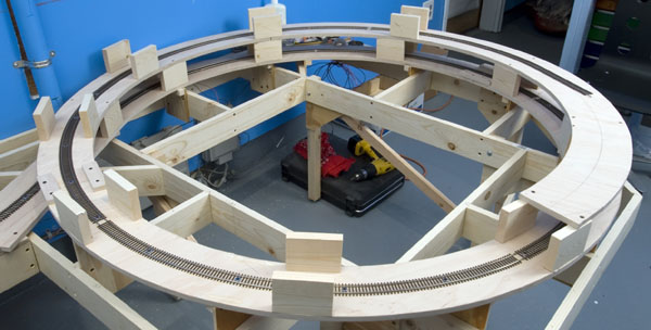
My helix was built on a 27″ radius curve, which is broad enough for even my larger steam engines. A rise of 31/2″ per loop gives it a 2.07 percent grade, which isn’t too steep.
My goal was to build the approach and first level as carefully and strongly as possible, with a consistent curve radius and grade. If the helix were uncurled as a tangent track, the grade should follow a straight line with no significant dips or steep sections. When a small steam engine is struggling uphill with a near-capacity load, a consistent grade makes it easier for the train to reach the summit.
I use a specific method of building a helix and laying track, but there are many different ways to build them yourself, including commercial helix kits. The principles presented here should work with most construction techniques.
Crunching the numbers
Any helix project should start with research. You need to know how much side clearance your largest equipment will need so you can determine minimum support spacing, roadbed width, and vertical separation. The vertical separation and curve radius determine the grade of the helix track, so all these details come together in the end.
I started by laying a piece of flextrack curved to a 24″ radius on a piece of Homasote. I then marked the 5″ estimated roadbed width on either side of the track centerline. I use ¾” wood as supports for each deck, so I know how much of the roadbed width will be taken up by the supports.
I had decided the clearance from deck to roof would be 3″, more than enough for my 1920s-vintage rolling stock. Since I was using ½” plywood for the roadbed, this gave me a total of 3½” of rise per turn.
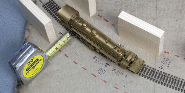
The longest articulated I own, a Weyerhaeuser 2-8-8-2, is a bit arthritic in its joints, so I decided the 24″ radius would be tight. An SP 4-8-2 and 2-10-2 likewise worked, but both would run more easily on a larger radius.
I wanted absolute reliability in the helix – it’s really tough to get in there and re-lay track or make any drastic changes after the fact – so I increased the radius to 27″, even though that would end up taking more square footage. I re-laid the test track, re-marked the deck width, and checked my locomotive clearances again.
Expanding from a 24″ radius to 27″ meant the grade dropped from 2.32 percent to 2.07 percent. That’s not much, but it may make a difference for smaller locomotives.
From the ground up
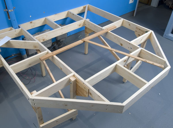
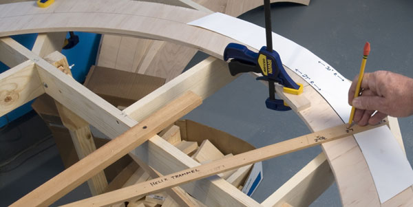
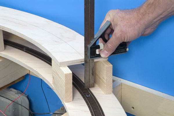
For my roadbed, I chose furniture-grade plywood, which is more expensive but worth every penny, since it’s flat, smooth, and strong. I laid it on the base and used a cardboard curve template and trammel, as seen in fig. 3, to ensure that the curve was indeed a perfect circle.
Next came 12 risers of ¼” plywood with ¾” square cleats, which I attached wherever the roadbed intersected the frame crossmembers. Some may view 12 risers as excessive, but they made the helix strong and solid. Nobody will be climbing on the layout, but the helix will be strong enough to support its own weight and to be moved without falling apart, if needed. The riser cleats were then screwed to the roadbed, but not yet secured to the frame.
Making the grade
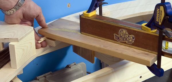
Next came the grade-setting process. My 4-foot-long carpenter’s level didn’t quite reach across the helix, so I clamped a piece of 1 x 6 to one end as an extension. Bridging the level directly across the center of the helix from the grade starting point to the half-turn point, I shimmed the end of the level on the low end – including the extension – to 13/4″ with wood scraps and some thin balsa shims, as seen in fig. 4. This distance is half the 31/2″ rise from one turn to the next. I lifted the roadbed opposite until it was level, and clamped the riser in place.
I then worked back to a point one-quarter of the way up the circle, which meant the shim had to be one-quarter of 31/2″, or 7/8″, and adjusted the riser and roadbed accordingly. From that quarter-turn point, I used the 13/4″ shim to level halfway across the loop to the three-quarters-turn point.
During the leveling process, I frequently hunkered down and eyeballed the roadbed from the side. This gave me an immediate idea if there were any obvious or significant changes in grade from point to point.
Gaining altitude
I temporarily fitted the next roadbed segment and installed the 3″ spacer blocks. I attached them with a bead of wood glue in the center of the block, plus two dabs of hot glue on the ends to hold them in place until the wood glue dried. Clamps held the blocks for a few minutes until the hot glue set.
With the next segment of roadbed clamped into place, I used the level to verify the elevation of the first section of the second level.
This process calls for some fiddling and adjustments, but I didn’t rush it. Once the first circle of roadbed was in place, the rest of the helix went together easily and accurately.
After I’d established the elevations for the first roadbed loop and checked the levels twice or more, I screwed the risers into place. I also used a small torpedo level to make sure the roadbed was even side-to-side before securing the risers.
Adding the track
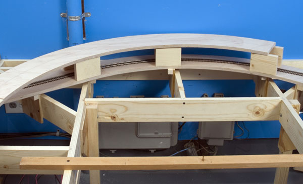
Next, I installed the first section of Atlas code 83 flextrack, which extended just past the point where the second-level roadbed overlapped the first. (See fig. 5.) It’s important to lay the track now, as it’s much more difficult to do when there’s only 3″ of clearance. I secured the track directly to the plywood with screws and washers, in case it needed to be adjusted before moving on to the next loop of the helix (but we’ll get to that shortly – Ed.).
At this point, I ran a train up and down the loop to verify that all the track joints were trouble-free. This was the time to check, while the screws holding the track were accessible.
I coupled a smaller locomotive to a near-capacity cut of cars and watched closely as it slowly wound its way up the track. If the train changed speed, it would mean the grade wasn’t consistent, and some riser-height adjustment would be in order. Patient inspection and cautious work at this stage pays off with consistent operation later.
Once the first level was secured and double-checked, I could begin construction on the rest of the helix in earnest. After that first level, the rest was relatively easy.
Keep these techniques in mind when starting your own helix, and it may end up as one of the most trouble-free parts of your layout.
Screw-down track
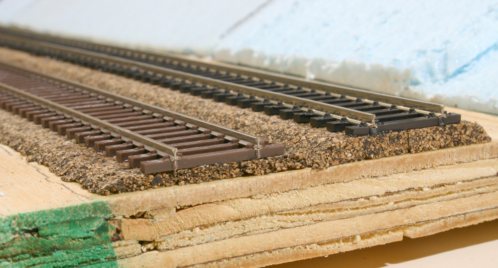
In a helix, it doesn’t matter how the track looks, because it isn’t a visible part of the layout. But since bulletproof operation is important, I wanted to be able to adjust the track during the construction process, so I opted for a slightly unusual system.
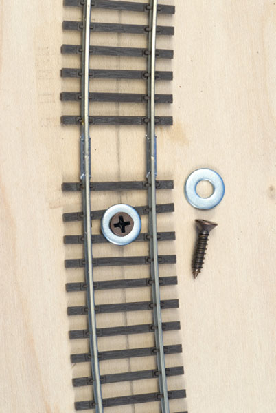
I secured the flextrack to the plywood using no. 6 x 5/8″ flat head wood screws and no. 8 flat washers. The screw heads almost, but not completely, fit through the washers, so the screw head barely protrudes above the thickness of the washer.
The combined height of the washer and screw head, when tightened gently against the plastic ties, isn’t enough to stick out above the railhead of code 83 track. Any locomotive pilot or coupler trip pin dragging severely enough to catch on these fasteners would already be causing trouble elsewhere on the layout.
The washers are small enough to allow some side-to-side fine tuning of the track location by loosening the screws.
Since the track wasn’t laid on cork, I wasn’t worried that the ties would compress into the roadbed and draw the rails too close together if the screws were snugged down a bit too much.
I’ve used these screw-type fasteners with great success.


Has anyone made a helix in an oval shape instead of a circle? I have more room for length then I do for width. If you have I would be interested in any problems associated with it.
Did a quite similar thing a couple of years back. Although for the spacing I calculated I needed a 90 mm gap (approx. 4″) between each subsequent road bed. I then cut the periodic between track support pieces at 90mm and used the drop saw to make sure each piece was at a 2 degree angle top and bottom, then wood glued those in place. My dual track system was based on 24″ and 26″ centered dual roads but was fitted up exactly the same way as here using the screw and washer method. I also left each fastening just the tiniest bit loose. By doing this it made sure there was ample expansion and contraction for the track with increases and decreases in temperature. The two roads in total averaged out to pretty close to a 2 degree grade. I also applied an outer (total length) piece of external bracing at every 90 mm track support area. Everything came up a real treat and runs well. If there was some way of uploading the finished article here for clarity I would but it is very close to what you see here, except for my external braces …. Quite easy once you get set up and started, the rest just flowed …. Cheers, GregS
The grade calculations are correct. The circumference of a circle is PI time diameter, not radius. The helix curve has a 27-inch radius, so the diameter is 54 inches. 3.14 times 54 = 169.56. 3.5 divided by 169.6 = 2.06%.
Am I the Only one doesn't think the math for the grade was done correctly? Pie x 27 = 84.82 which is the distance travel on a 27" dia circle. The track has to 3.5" every circle. Which would 4.1% grade not 2.07%.
Thanks for the info. I hope I can copy your techniques and make a great helix too. but mine may be more difficult as I want to incorporate 2 or 3 tracks.
Excellent photo's Im going to use this method on my new HO scale layout in a 17x13ft room
Good information! Thanks for the ideas concerning the basic math and building methods.
that's an epic helix and i hope to see more great ideas about these later on
I'm looking forward to build the helix for my two level layout
Works great many thanks Jeff.
I like the concept and the way the segments are put together. Looks less complicated than other systems I have seen.
hello, greetings, how many inches have the segments of the baseboard, thanks
THANKS
This was just simply great. Thank you very much!
Excellent. You covered everything but the math and transitions into and out of the helix. Hopefully the guide you mentioned will cover that. I now am less apprehensive about tackling this project.
At last. A "how-to' article that doesn't skip over the hard parts. With a few exceptions, EVERYTHING I needed to know was included. Bravo.
QUESTION: Since 'Homosote' and cork weren't used as sound-deadeners, what did you do to prevent "drumming" or grinding or other noises that are created when the track is adhered directly to the underlying wood?
This is the info I was looking for Im just getting started on construcking a helix thank you fpor the info.
very interesting and thorough. mine will be similar but just a turnback curve for now. later I'll us this same base todo the helix.
Thanks for a great article. I will be using your tips to build a double track helix on a layout I am constructing now. Very timely and informative.
How long are your roadbed segements? How do you splice the segments together to maintain the desired 3" clearance from "deck to roof".
thanks! great job.im going to use your techniques
The K.I.S.S. principal at its best. I will definately be employing these techniques to build mine this winter.
Excellent article. I m very new to MR and using "N" Scale. I veyr much liked the comments and interested in what the "N" Scale guys had to say. Several comments were made and well caputured in TED BROWN from ARKANSAS said:
GREAT article, and is about all one would need – so long as there are no turnouts at intermediate levels between top and bottom of the helix. Would have helped if transitions had been described to ease into and/or off of the gradient. Was there follow up to these thoughts?
Many thanks to all.
Jeff Sarsons
Thoughtful ideas on a complicated project. Thanks.
Very interesting and informative article. I am new at this hobby so I'm probably a couple of years away from my first helix (crawl before you walk, walk before you run theory). However, your article has probably solved one of my present problems, that is cars jumping the track for no good reason. I think I'm unintentionally imbedding the nails to deeply into the foam bed thereby pulling the rails slightly together. Your article solved my problem with de-railing. Thanks. (PS. I've hung up my framing hammer and purchased a tacking mallet, what a difference the proper tool makes.)