


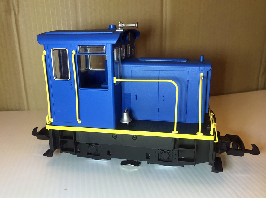
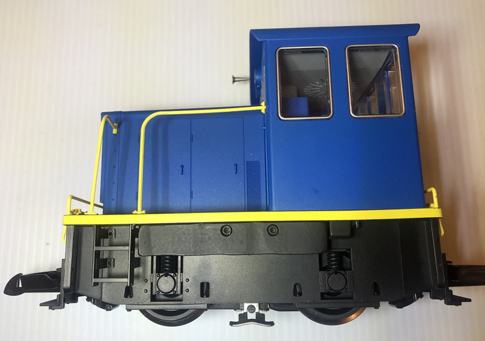
Increase traction of PIKO switcher: I bought a PIKO America GE 25-ton engine for my railway. As I ran the little diesel on my layout, it went around a couple of times nicely over the trestle and under the tunnel. I hooked two cars to the engine, and sent it on its way again. As it began to negotiate the 3.5% gradient, its wheels started to spin. I tried again sans a train, and it did just fine. For the engine to do its job on the incline, I’d need to increase its traction.
I’m not an expert on how much weight would be appropriate for this type of engine, but I weighed two small engines I have from another manufacturer, and both came in around 3½ lb. each. These engines don’t have a problem pulling a couple of cars up the incline.
The PIKO America engine weighs about 2 pounds, 15 ounces, as it comes out of the box, so I thought I could add about a half-pound of weight.
Adding weight to PIKO’s switcher
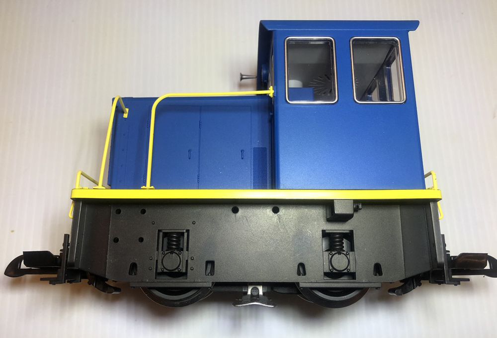
I decided to add weight under the running boards. As a bonus, the chassis has two holes on each side, so I wouldn’t need to drill any new holes.
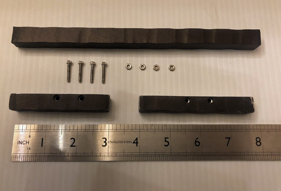
Materials:
(2) ½” square iron balusters pieces (leftovers from a stair job)
(4) M2.5 X 16 hex stainless screws with the appropriate hex nuts
1/8” drill bit
3/16” drill bit
Sandpaper
Matte black paint
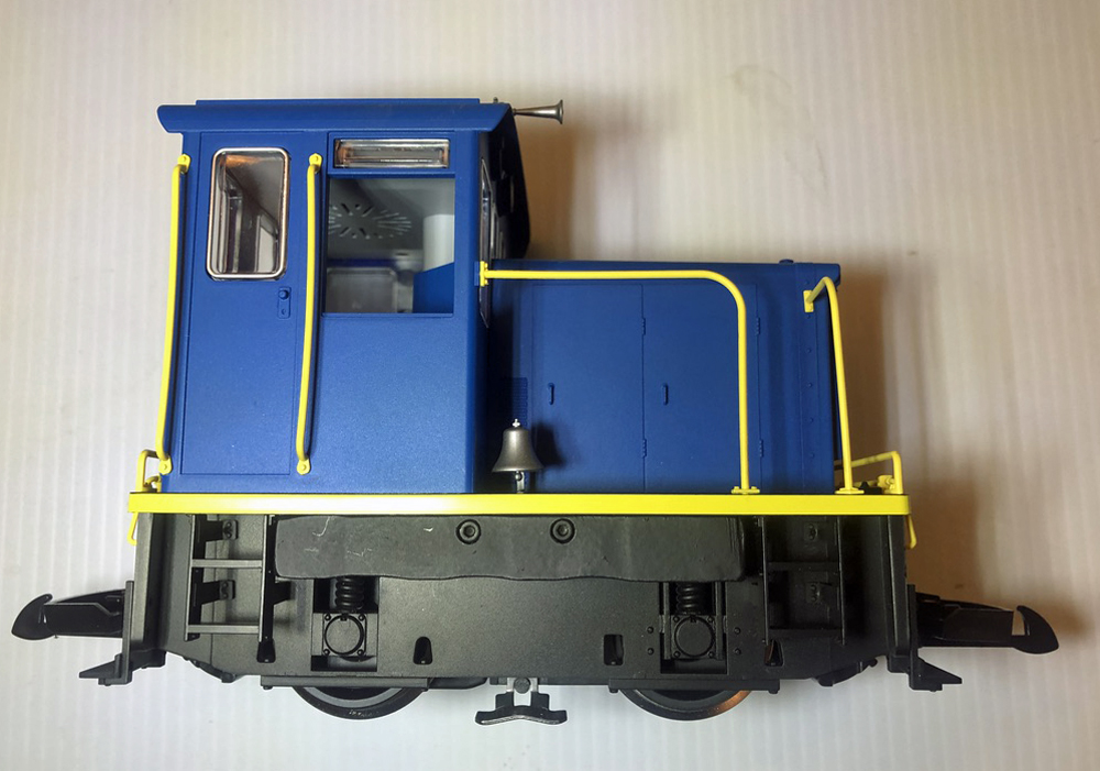
Lengthwise, the clearance under the running boards is different on each side of the engine. The space on left side is three-inches long, and three and five-eighths inches long on the right side. In my junk box, I found leftover pieces of ½-inch square iron rods that I thought would fit well under the running boards.
The combined weight of the iron pieces, screws, and nuts is approximately 1/2-pound, giving the engine a final weight of about three-and-a-half pounds.
Carefully remove the steps from each side. Drill two eighth-inch holes per metal piece, matching the location of the existing holes in the chassis. If you prefer, countersink the holes with a three-sixteenths-inch bit, so the screw heads are flush with the edge of the metal.
Loosely add the weights under the running boards, then test the engine. My engine pulled the two cars up the gradient without any problems.
Sand and wash the metal pieces painting them matte black. After the paint dries, mount each weight with the two screws and nuts. (Note: For one of the nuts to fit in each side, you may need to remove a bit of plastic inside the chassis.)
Since I was looking for better performance, I did not do much in terms of esthetics. If you prefer, disguise the weights with details such as hoses, hinges and handles. Replace the steps, and your engine is complete.


Looks like a great thing to do