
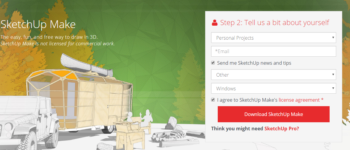

You must fill out the form in order to get started, shown in photo 2. Don’t let the “Professional Work” drop down box intimidate you. If you use the drop down you will find “Personal Projects” and that will completely change the form.
Here we are with the “Personal” form (photo 3). I used “Other” for why I am using this program and I chose “Windows”. Mac users will change this drop down to MAC to get an Apple version. I checked the “Send me SketchUp news and tips” because I find their newsletter informative. Beware, you could be getting advertising that you perhaps do not want. Select “Download SketchUp Make” and the program will start downloading.
You will get the screen in photo 4 while the program is downloading. They describe the steps that you must take to properly install the program. The program that is downloaded is SketchUpMake-en-x64.exe. Follow the steps shown and install the program, then you will be ready to start.
Note: Notice in the lower right hand corner, they have a question for you: “Beginner?” They have numerous examples and instructions for you to practice using the program.
Locate the icon on your desktop or in your programs folder. Execute the program by double clicking on the icon (photo 5).
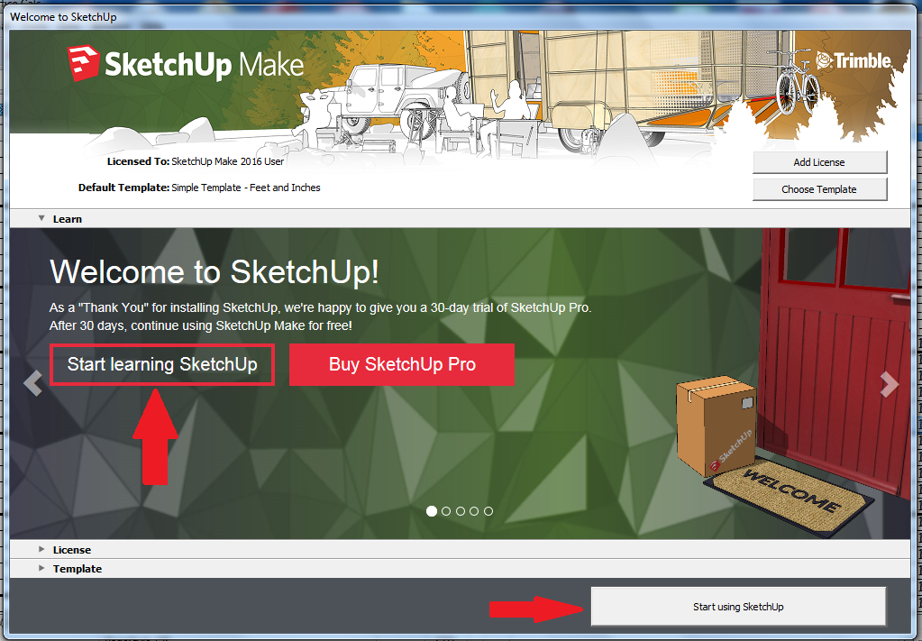
You will get a welcoming screen such as photo 6. One arrow that I have added shows a good place to learn more about SketchUp. The arrow in the lower right portion of the picture to the right is where to go to start SketchUp.
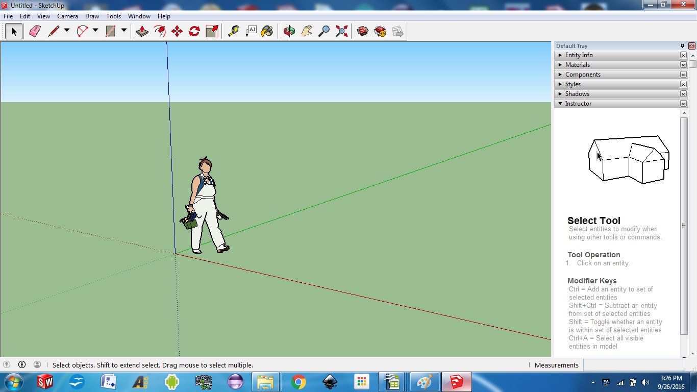
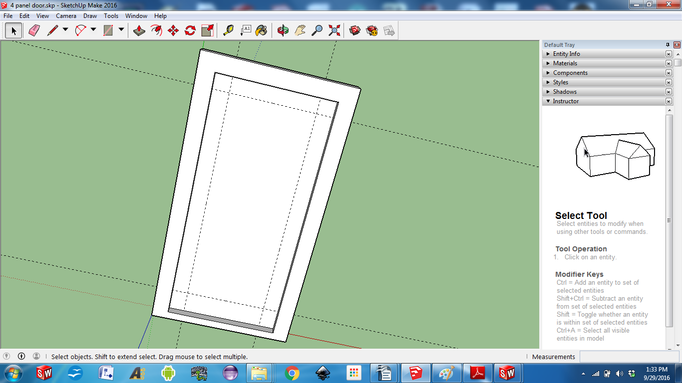
Clicking the “Starting SketchUp” button, you will get the drawing screen shown in photo 7, tool bars and “Default Tray” pull down menus.
The first thing I do is to click on the worker graphic and press delete. I do not need to see the young lady and her toolbox while I am drawing.
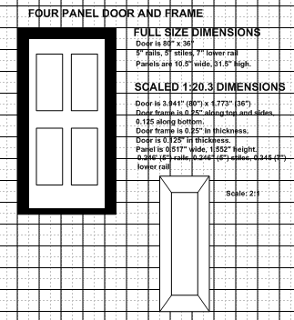
As I’ve mentioned before, I am building a factory building. The building needs a door so I went to the front door of my home and made some measurements. As usual, I make notes and scale the numbers, so when I do the model I have these numbers ready (photo 8).
Putting the model into SketchUp
I am going to use the following toolbars – At the top: Principal, Styles, Views, Construction. On the right side: Drawing, Edit. On the bottom: Measurements. Another thing to look at is the red axis is considered to be the X axis, green axis is considered to the the Y axis and the blue axis is considered to be the Z axis. When entering numbers they can either be in decimal or fractions.

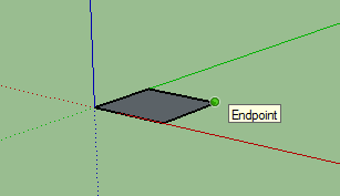


Now at the origin, left click and hold the button of the mouse and move the cursor along the X-Y axis (photo 10). Release the button. Any size will do right now.
Before you do anything else, type 2.273 and 4.316 and press enter. You are now entering your desired dimensions of the rectangle. 2.273 inches in the X-axis and 4.316 in the Y-axis. These will appear in the lower right hand corner of the sketch (photo 11).
You will notice that the model is very small. You can zoom to have the model shown in the entire window is to use the “Zoom Extents” button as shown by the red arrow (photo 12).

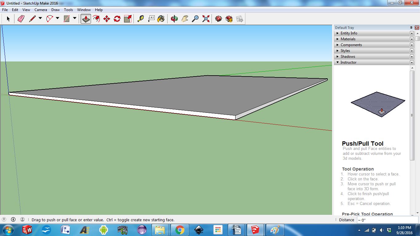


We want the door frame thickness to be 0.25”, so type in 0.25 and the box will be formed (photo 14).
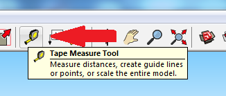
Now we need the tape measure tool to set the drawing lines (photo 15).
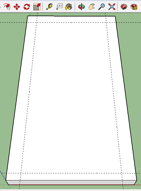
Hover over the bottom line and left click the mouse button. A dotted line will appear over the bottom line. Now move the cursor so the dotted line appears on the lower portion of the door. Type .125 and press enter (photo 16).
Now hover over the top line and left click the mouse button. A dotted line will appear over the top. Now move the cursor so the dotted line appears on the door. Type 0.25 and press enter. Repeat the 0.25 lines on each side (photo 17).
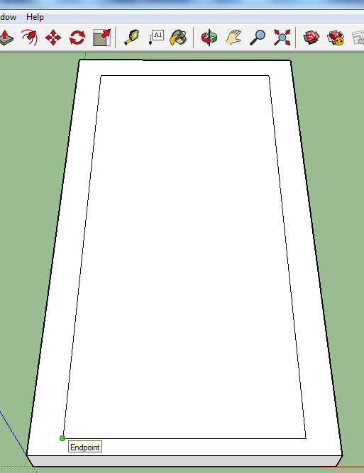
Select the rectangle tool. Put your cursor on one corner of the rectangle formed by the guide lines and left click and hold the mouse button. Move the cursor to the opposite corner and release the mouse button (photo 18).
Now select the push-pull tool. Hover over the inside rectangle and click and hold the left mouse button. Move the cursor so the rectangle goes “inside” the cube. Type 0.125 and press enter (photo 19).

At this point we need to create the panels inside the door. To start this process, select the rectangle tool and put the cursor on the lower left corner of the guide lines. Click the left mouse button and move the cursor to the inside. Type 1.552, .517 to set the size of the rectangle. Repeat for each of the additional corners (photo 21).
Now delete the guidelines by going to Edit->Delete Guides.
Select the push-pull tool and hover over one of the rectangles and left click. Move the cursor so the rectangle goes “down” or inside the door. Release and type 0.625 and press enter (photo 22).
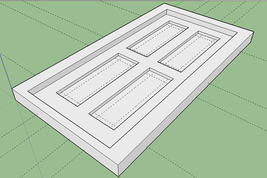
Note: the guidelines will extend through to some of the rectangle so every depressed side of the rectangle will need to have guidelines added.
Now we are going to extrude the panel itself. Select the rectangle tool. Put the cursor on a corner of one of the rectangles made by the guide lines and left click the mouse button. Move cursor to opposite corner of the rectangle and left click again. Repeat for the other panels (photo 24).
Select Edit->Delete Guidelines.
Now select the line tool. Put the cursor on one of the corners of the small rectangles that we just made and left click the mouse button. Move the cursor to the near inside corner and left click. Repeat at each corner of each of the four panels (photo 25).

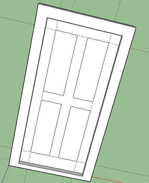
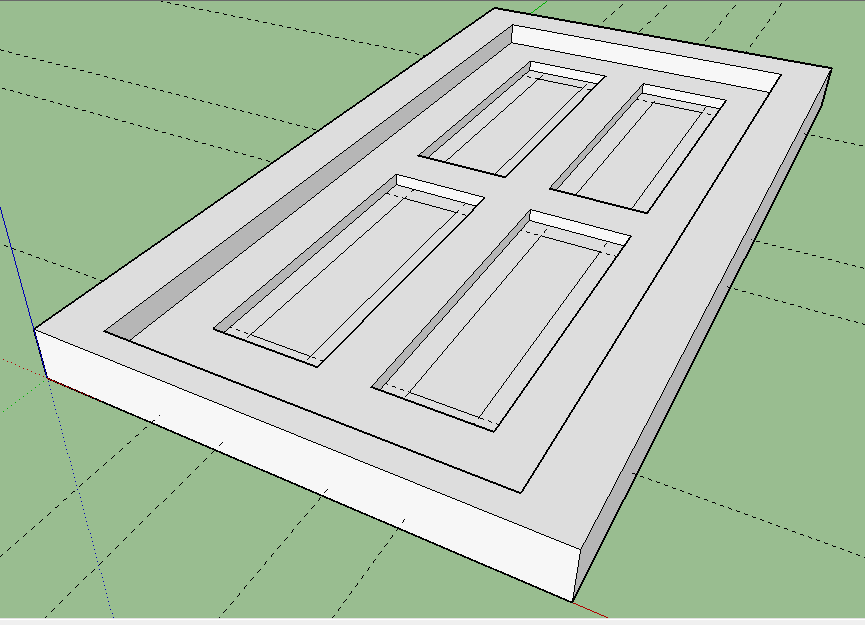
To do this operation, it might be helpful to change the view to one that is more on the side rather than above the door. Hover over the inner panel of one of the panels and left click the mouse button. Move the cursor to “pull” the inner panel up along the blue axis and type 0.0625. This might take a little practice and you might have to change some of the views to see what is happening. Repeat this for each of the remaining panels (photo 27).
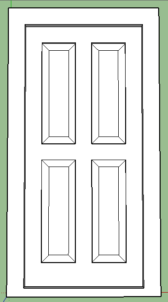
The door is now complete. Don’t forget to save your work often.

Now you have a .skp (SketchUp) file. Either you can deliver the SketchUp file to your 3D printer supplier or you will have to jump through a couple of hoops to generate an .STL file that the printer software can read and print it out.
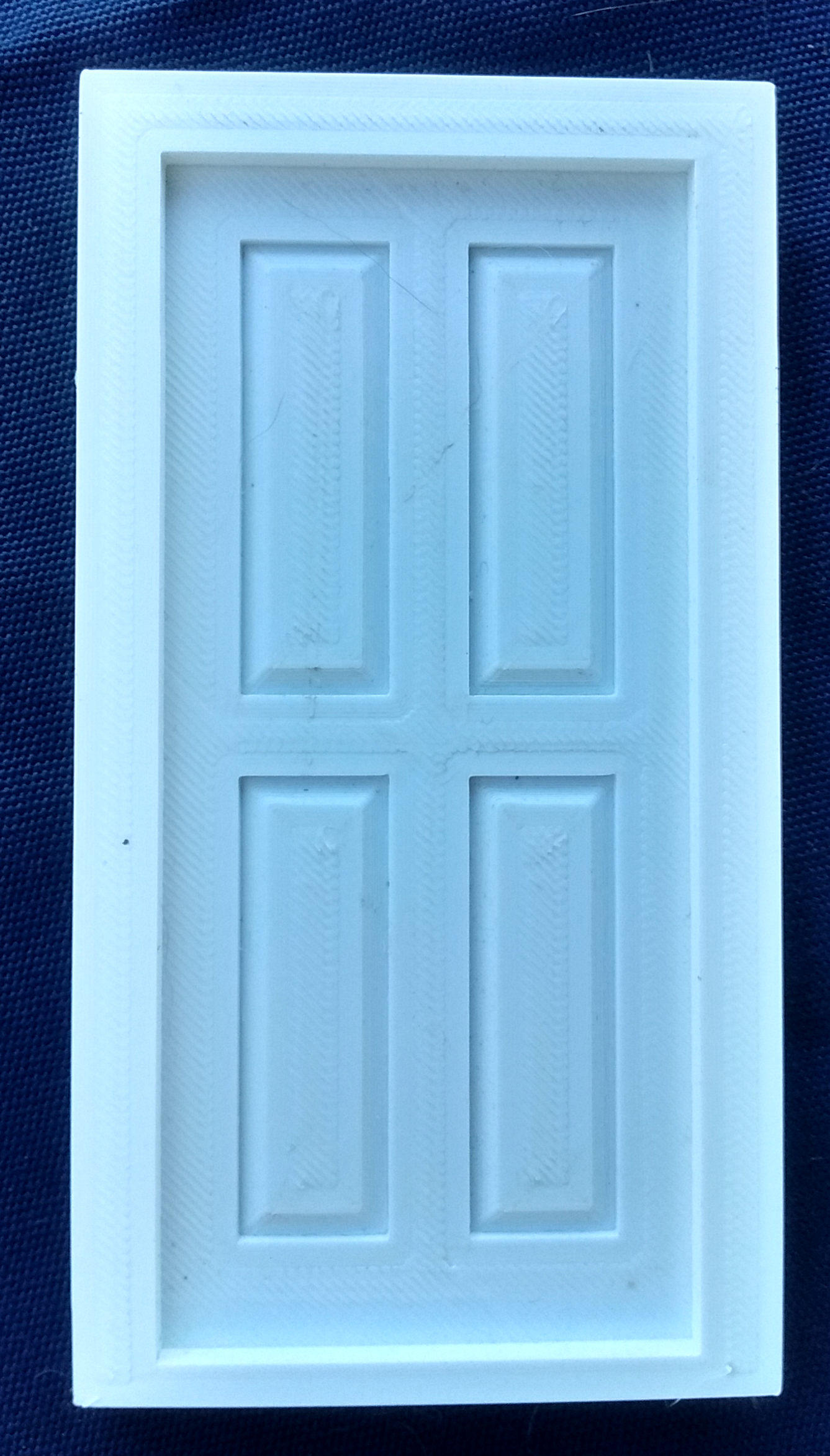
Photo 28 shows what was printed out. The next question is, how accurate is the printout? The horizontal distance across the door and frame is supposed to be 2.273”; I measured 2.277” and vertically across the door and frame is supposed to be 4.316”; I measured 4.302”. Pretty good, I think.
This door is in 1:20.3 scale. I am planning another building that is a little further off in the distance and given the perspective of the viewer a 1:24 scale would be good.
Here is how I did it: It is all done in the printer interface software. In this case, it is the MakerBot Desktop that came with my printer.
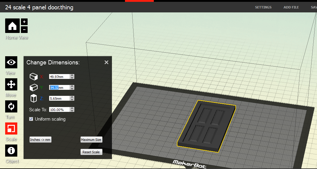
If we look at the dimensions of the object the height of the door and the frame is 109.32mm (4.304”) and the width of the door and the frame is 57.92mm (2.280”) (photo 29).
To reduce the door size to 24 scale, I will use the downscale arrows next to the numbers. For example I want 109.32mm scaled down to 94.191mm (photo 30).
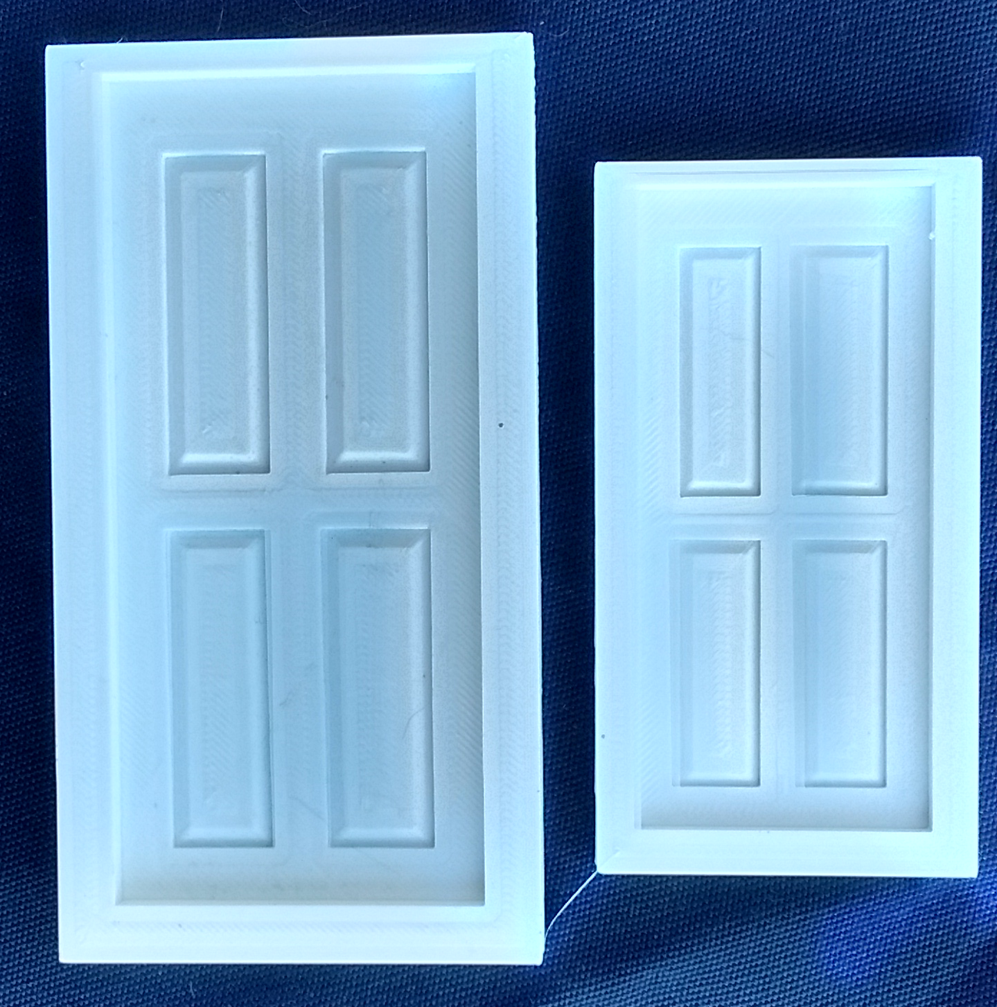
I then printed this out. Photo 31 shows the results.
Attached is the SketchUp file so you can manipulate it as needed for your project and experiment with the door. Also attached is the .stl files for the 1:20.3 scaled door and frame so you can print out what I have created here. You can send it to your local 3D printing facility, or go to www.3Dhubs.com and find a printer near you, or drop me an email and I can print it out for you (sberneberg@yahoo.com).
Next time, I am going to work with parts that you cannot or should not do with the FDM (Fused Deposition Modeling) techniques. (For those of you who want to look ahead, check out Resin Printing or SLA Printer.)