


As a child, I had done the typical progression from Marx wind-up trains to Lionel O-27 to HO. As a teenager, I put them away. Then in 1993, I saw a French JEP Toy Train set similar to Lionel and Marx. When I saw the JEP running, it reminded me how much fun the Lionel had been. So I started buying old Lionel and Marx trains.
My first attempt at building a layout involved a load of O-27 track. Then I built a modular O-27 layout so I could run trains in the garage, at train shows, or even my back yard. My friend Jim Behling invited me to join weekly operating sessions on his HO layout. He introduced me to railroading with schedules, waybills, and the challenge of switching freight cars. This provided the missing part of model trains for me. I enjoyed watching trains move and all the parts of building a layout, but switching to a schedule would give my railroad purpose.
I started planning a layout for railroad operation but also for toy train display. I wanted a large rail yard with a turntable, towns with industries to switch, mountains to overcome, and hidden tracks for holding made-up train sets. I has empty land behind the garage, so I decided on an addition for the layout and a metal shop.
I had visited several layouts with duck-unders and removable sections, but I could imagine that crawling under the layout would get hard on my knees. I visited Bill James’ layout, which shared space with his wife Marilyn’s sunroom. The entire layout hung overhead from threaded rods and had openings for the operators to stick their head up to see. Bill could do all the under the table wiring standing up! My garage had a ceiling that was 10 feet at the eaves and 13 feet at the ridge, so I could put the operator’s floor at 3 feet and still have 7 feet of headroom at the eaves.
Track planning and design
I researched layout design with books including John Armstrong’s Track Planning For Realistic Operation and Albert Sorensen’s Model Railroad Scenery & Detailing. To allow for the widest curves an around the room layout seemed best. For display of toy trains, a double-track main line would be nice, and if it could loop around the room three times, it would make for a fairly long run. In Armstrong’s book I discovered the idea of reversing loops on a grade. In the uphill direction, a turnout would take the train to a loop below the mainline that returned to the downhill track. Just the opposite in the downhill direction, the train would loop over and back. I had also read of many English layouts with what they called “shuttle yards,” where several tracks large enough to hold a whole train could be aligned to the mainline without turnouts.
I named the yard after my parents’ hometown of Nauvoo, Ill. The two other towns are named after Jim Behling and Vernon Scarbrough, who helped greatly. The mountain area, Ruth Mountain, is named after my Aunt Ruth, who always made sure I received trains at Christmas. The local businesses are named after all my other helpers.
I grew up in Burlington, Iowa, namesake of the Burlington Railroad. Charles Perkins, the president of CB&Q, so loved the area that he insisted the railroad always keep Burlington in the name. I have a fondness for the CB&Q, but I wanted something different for my layout. I became interested in railroad nicknames and found another local railroad, the Minneapolis & St Louis (M&StL), which had a catchy nickname: The Misery & Short Life.
When I cleared the land for the garage addition, I had space for a 24 x 24-foot room. I kept a sketchbook of my ideas and combined them in a layout drawn on a 2-D computer-aided drafting (CAD) system. While construction of the addition was underway, I built a 1” = 1’-0” scale model of the room and the layout from foamcore. This proved the room arrangement for the storage shelves and metal shop. In three dimensions I could also see design flaws that had looked OK on the 2-D drawing board. I punched four holes in two walls that ran the main lines outside the room on two sides.
With the building finished, I installed the ceiling lighting behind valances made from 1 x 6 boards and added track lighting. The lights and layout power are controlled by X-10 modules that allow control from several panels. After the air conditioning ducts were installed, I painted the ceiling and walls sky blue and added clouds and glow-in-the-dark stars before there was anything in the way.
I would set up the modules and run trains between days of construction. I found a deal on some industrial shelving, so I built the shelves to provide storage space and also support for the operator’s floor. Instead of cloth skirts around the edge of the layout, I made plywood panels topped with oak trim that could also support the operator’s side of the layout. The far side would be supported by the walls. Without the conventional legs and cross braces, this would leave a maintenance tunnel under most of the layout I could walk through standing up. The back side of the plywood skirt would also serve as a wiring board.
I built in 23 feet of shelves under one side of the layout for all the books and magazines that accumulate. Three sides of the room have four-foot-wide tables attached to the wall for trains and the fourth has eight feet of space for the major mountain range. This violates the “arm’s length” rule, so I added several access holes. To reach these access holes you have to stand on a stepladder, but it’s better than crawling under tables.
I didn’t want to have to paint around the tracks later, so I painted the track boards gray and used a sponge to splotch brown paint to make it look less like plywood. To make cutting the roadbed support boards easier, I cut a template from tempered hardboard the size of the curved roadbed with slots for the two track centerlines. I could put this template on scrap plywood and cut out sections as I needed them. The track radii were 48” and 52” (O-96 and O-104), so the radii of the edges of the boards were 46” inside and 54” outside. I used ½” plywood with 1 x 4 pine strips to make a “T” shape for stiffness between supports.
For reliability, Jim and I soldered two wire feeders to each section of track. To keep the noise down I cut old inner tubes into 1” strips. I stabled one strip of rubber to each side of the track center line, then screwed down GarGraves track. After applying granulated rubber as ballast, I used diluted white glue to hold it in place. I used GarGraves turnouts, mostly the O-100 model and a few O-42 in the towns. I’ve added guard rails to some to improve reliability.
I wanted slow-motion switch motors, and to save money, I built my own from gear motors made for microwave ovens. They mount under the roadbed with only an inch of piano wire showing. Each motor has a control button that indicates the position and motion of each turnout. I used modular telephone connectors so motors or controls could be easily replaced if they failed.
After six years, we completed the main lines and had a Golden Spike party and a day of train operation in 2004. Jim provided champagne and glasses from an Amtrak trip.
Scenery
It was time to build scenery, working from the walls to the center of the room. It would take a load of ground foam to bring the mountains to life, and I wanted to also use ground foam to make trees. I bought a meat grinder to grind my own foam, then added coloring and dried it.
I pulled an old foam rubber mattress from the attic and carved it into mountain ridges. I added wood shavings and other trash to the mostly tan latex paint mix, and it looked good. I glued the ridge segments to plywood supports so I could finish them indoors and lift them into place. Thus I built a 24-foot-long mountain range.
To fill in the other scenic gaps, I found foam rubber carpet padding and started molding it over plywood forms. I pushed and pulled the foam until I liked the shape and used the staple gun to lock it in place. After protecting the tracks, I would apply the latex mix followed by ground foam. The mix was flexible, so it could be moved as necessary. Some parts were removable so they could be finished in the shop and hung on the wall later.
I built plywood tunnel liners to support the tunnel portals. I also put “ceilings” in all the tunnels to keep dirt off the track and prevent scenery from falling on the trains.
Control
I had planned on using TMCC for control of the trains. It worked for a while. The locomotive control decoders proved to be problematic, and when it stopped working altogether, I gave up on TMCC. Jim had converted to Digital Command Control (DCC), and it was working well. Older open-frame motors draw too much amperage, but modern can motors draw much less. If I only converted modern locomotives, there were DCC decoders available with more features for the money. It did require a couple of tries at rewiring the layout but all is well now. I have switches for each power block that allow running on DCC or conventional AC control.
Twice a month we have an operating session that includes waybills to direct the movement of freight cars to the industries. I’ve been adding Kadee couplers on the cars and locomotives to allow easy switching. The slamming of conventional toy couplers would often derail the trains, and wiring electromagnetic uncoupling tracks would be a nuisance. Kadee couplers latch gently and are easily uncoupled by magnets glued between the rails. Operating signals have been added to protect train crews as they switch each town. Each operating session adds to the “to do” list of things to fix and add.
At a glance
Name: Misery & Short Life RR
Scale: O
Style: around the room
Mainline: 800 feet
Minimum radius: 48″ mainline, 21″ sidings and yard
Maximum grade: 3.7%
Track: GarGraves
Roadbed: rubber strips with rubber ballast
Control: Digitrax DCC and conventional AC
Backdrops: Backdrop Warehouse
Acknowledgments
Thank you to my helpers: Bob Seigler, Fred Collins, George Dixon, Jim Behling, Jim & Nathan Delph, Rick Wiedmayer, Rodney Tucker, Roman Marks, Vernon Scarbrough, Walter Jenson, and my proofreader, Jamie George.
Photographs: Jim Behling, Jamie George, Jean-Raphael Guiton, Carl Blum
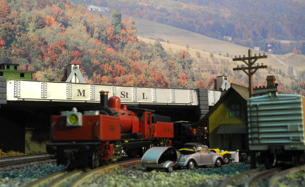
The Garratt passes the station in Jamestown. The M&StL bridges are extended Marx bridges.
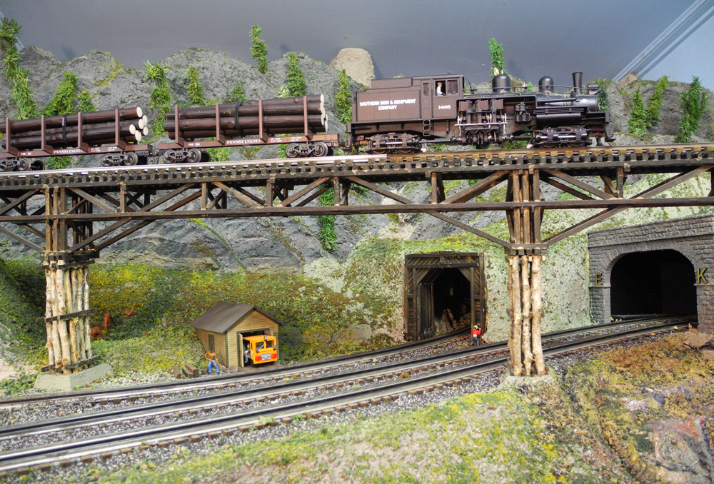
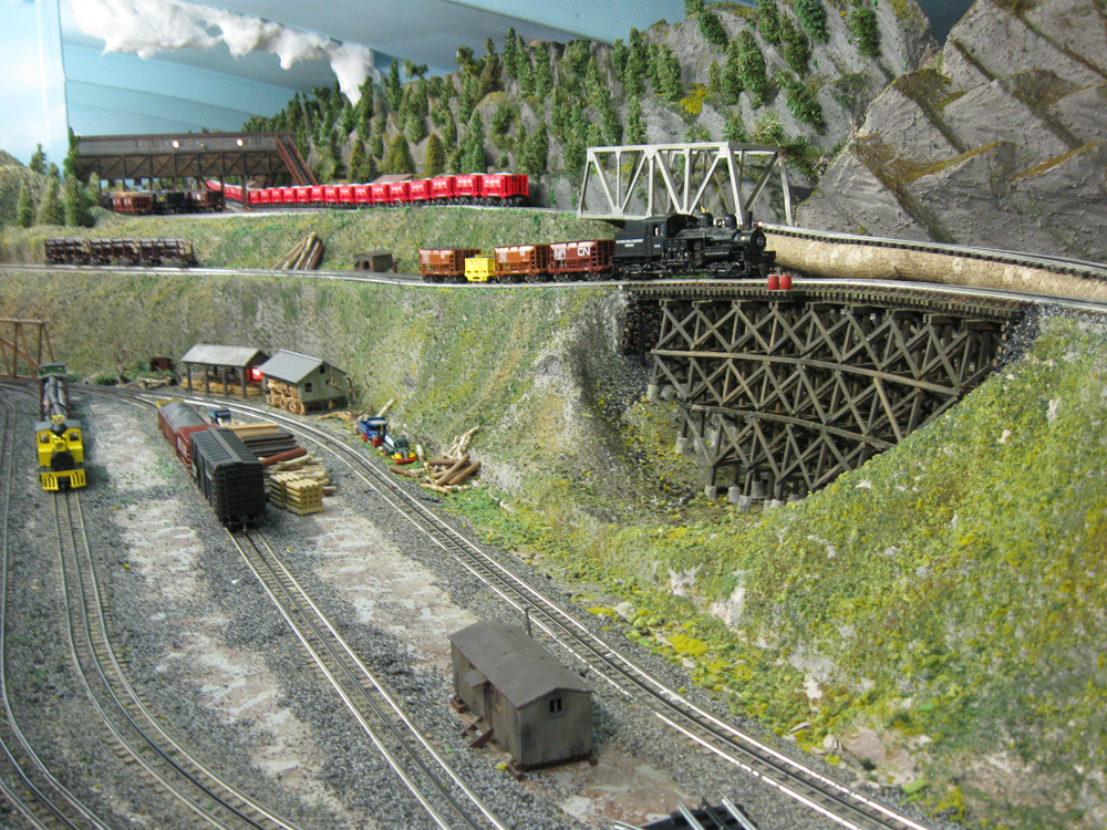
The Shay is at the limit of the bridge that allows trains to switch back to Herb’s Magic Mine. The mine also uses this bridge to dump tailings in the toxic dump below.
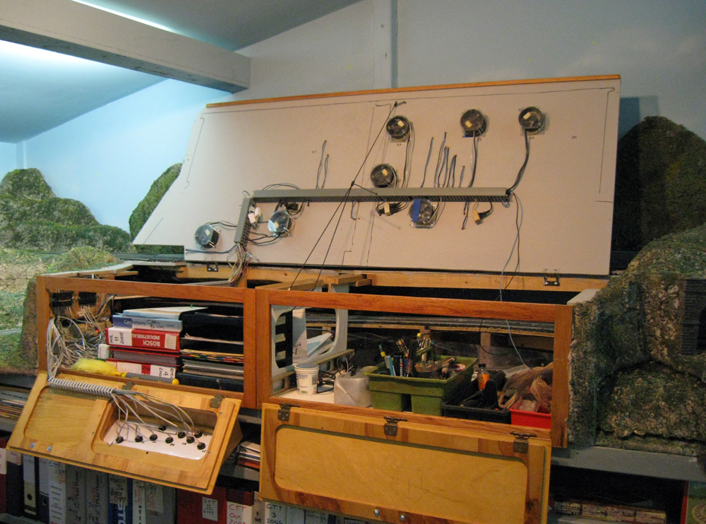
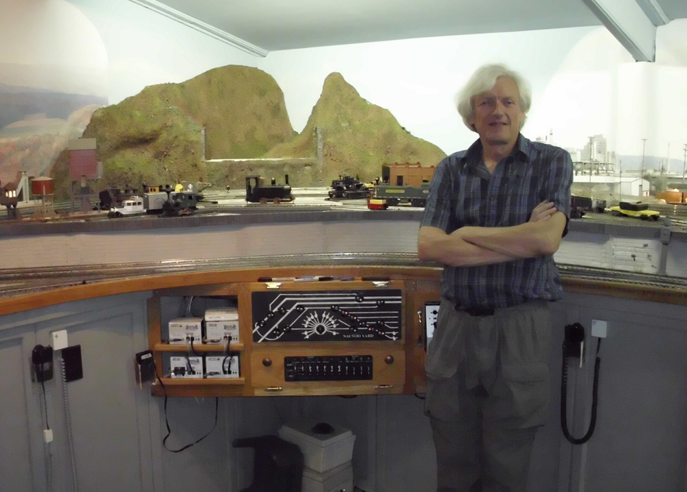
This is Vern Summit with the access doors open and the train table lifted. The round machines are turnout motors and the gray bars are industrial wire looms. The left access door also has a control panel.
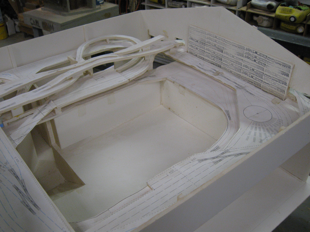
Carl printed out his track plan and glued it to foamcore to build this study model of the room in 1” = 1’-0” scale. This led him to route the mainline tracks through the wall on the west and north sides to uncover the yard tracks and make maintenance easier.
M&StL engine No. 44 pulls past the warehouse in Nauvoo Yard. The building was kitbashed from a Lionel Power House by Jim Behling. The locomotive was kitbashed from two K-Line MP-15 locomotives.
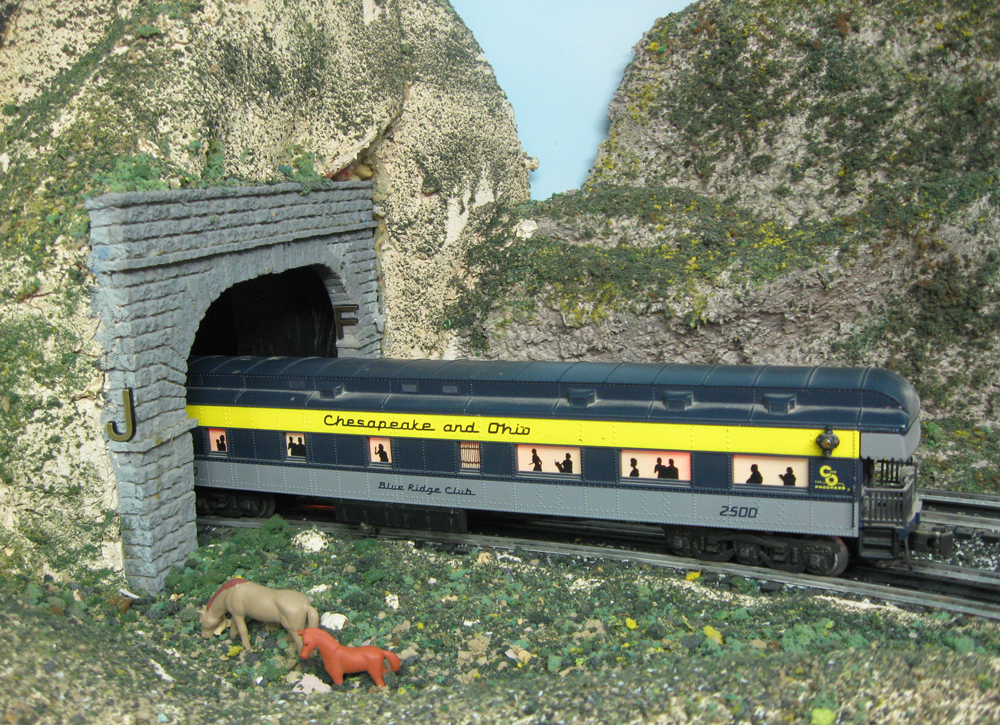
A Chesapeake & Ohio passenger train enters JF Tunnel. All the portals are lettered in alphabetical order in direction of travel.
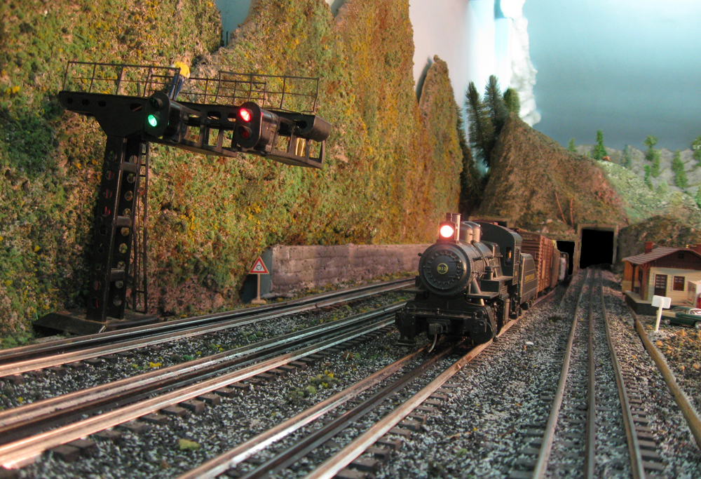
A Pennsylvania RR freight train passes a signal bridge Carl brought back from France. It’s now outfitted with Lionel lamps with LED bulbs. Signals protect the next towns.
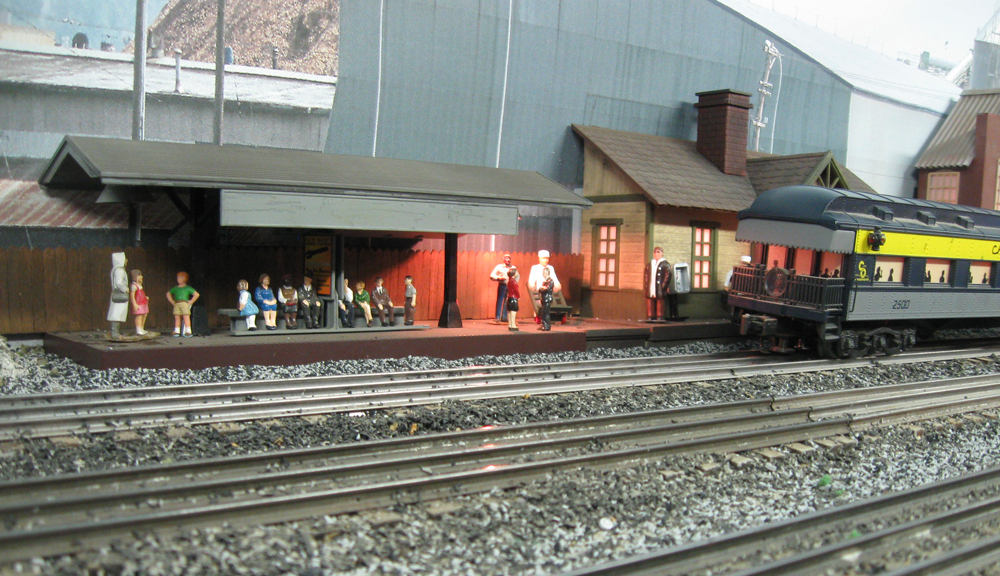
Passengers wait for the next train. The MTH Operating Passenger Platform make them disappear at the flip of a switch.
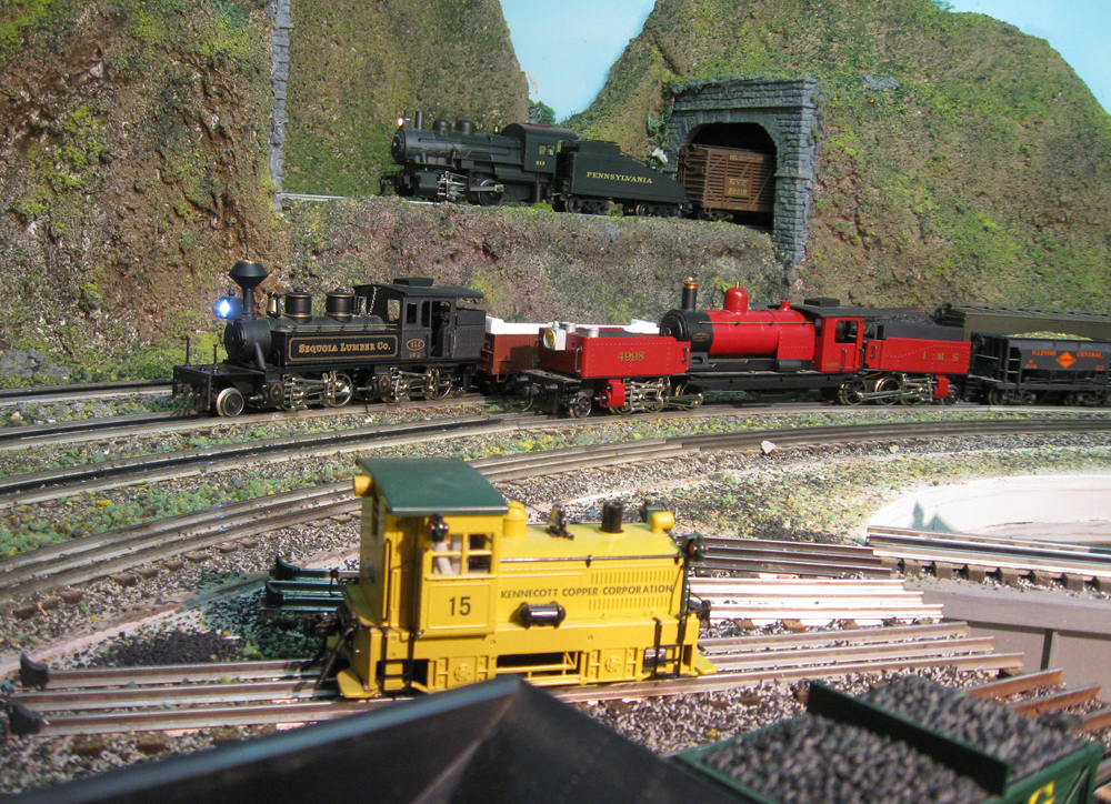
A Kennicott Copper Corp. Plymouth switcher waits on the turntable while the Mallet and Garratt pass. Meanwhile the Pennsy 0-4-0 pulls freight down from Vern’s Summit. Both tunnel portals lead out of the room.
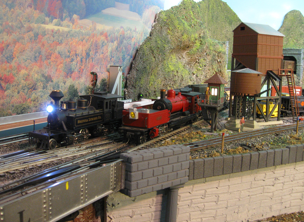
The Mallet and Garratt pass the guard shack at the turntable access. The yellow spot on the bridge marks the points for the operator’s reference. Photo murals are by Backdrop Warehouse.

I’m not into the O-Lionel stuff, but I must admit, you’ve done a stand up job (no pun intended) and I enjoyed the read – especially the progress through the design elements. Very nice.
Great article Carl.
Very interesting. There is no track plan shown, or in the Track Plan Database. Is there a track plan available?
No, I’m sorry, but we don’t have a track plan for this story.