Stuttering through switches can be fixed with this one-night project
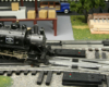
Some of today’s short-wheelbase locomotives have issues with the prototypical switches and narrow-angle crossings that make an O gauge railroad look realistic. Here’s a quick fix that will allow any locomotive - even this economical Bethlehem Steel saddle tanker from Lionel – to perform reliably over the troublesome trackwork.
THIS IS A PHOTO FEATURE. CLICK LEFT OR RIGHT ON THE PHOTO TO SEE ALL STEPS, OR CLICK ON THE PHOTO BAR BELOW IT.

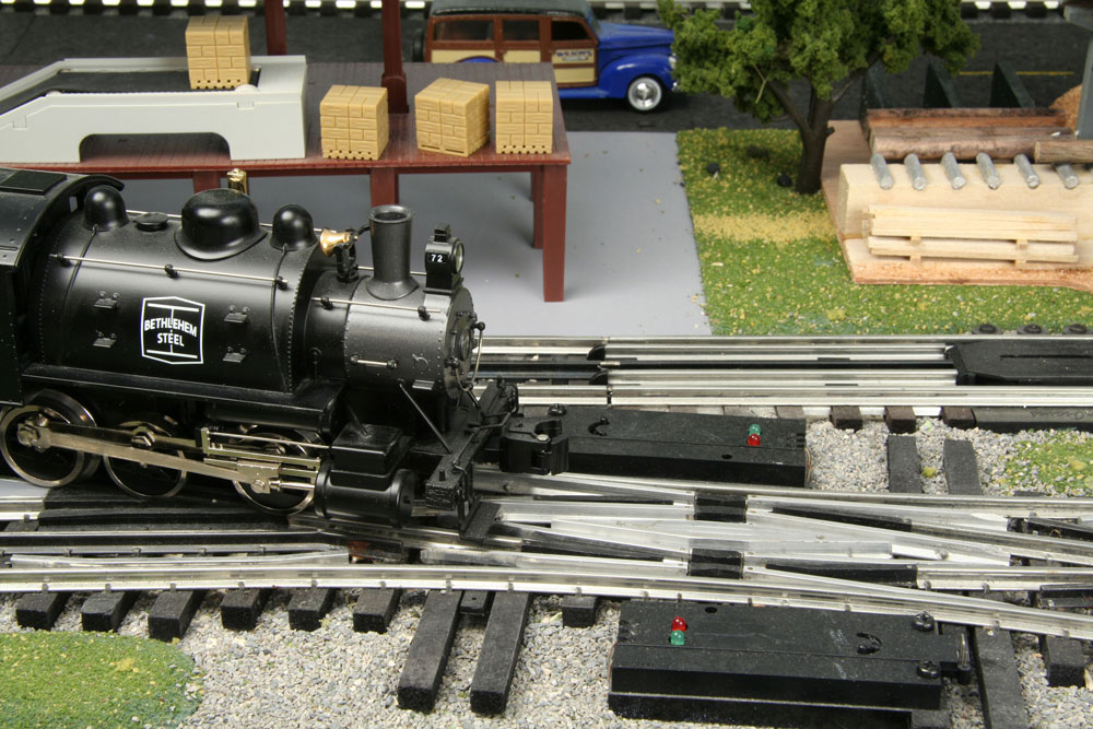
The bane of O gauge operators everywhere is having a small locomotive with closely spaced power pickup rollers – operating through long switches that stop ’em dead in their tracks. Here’ a simple, step-by-step process to keep the juice flowing! Photo by Peter Riddle
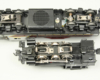
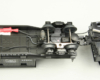
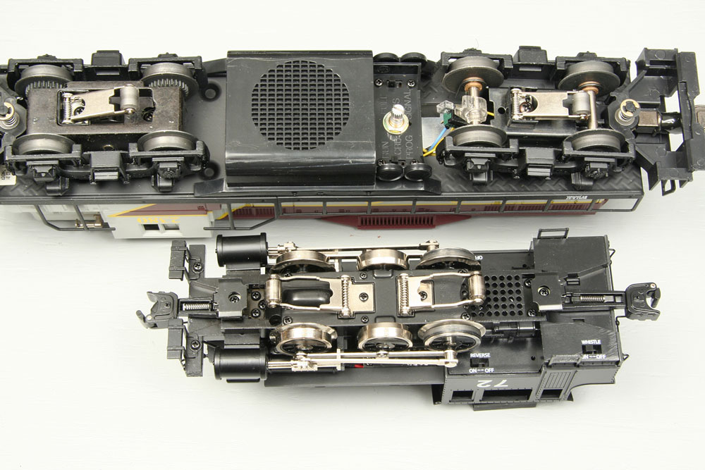
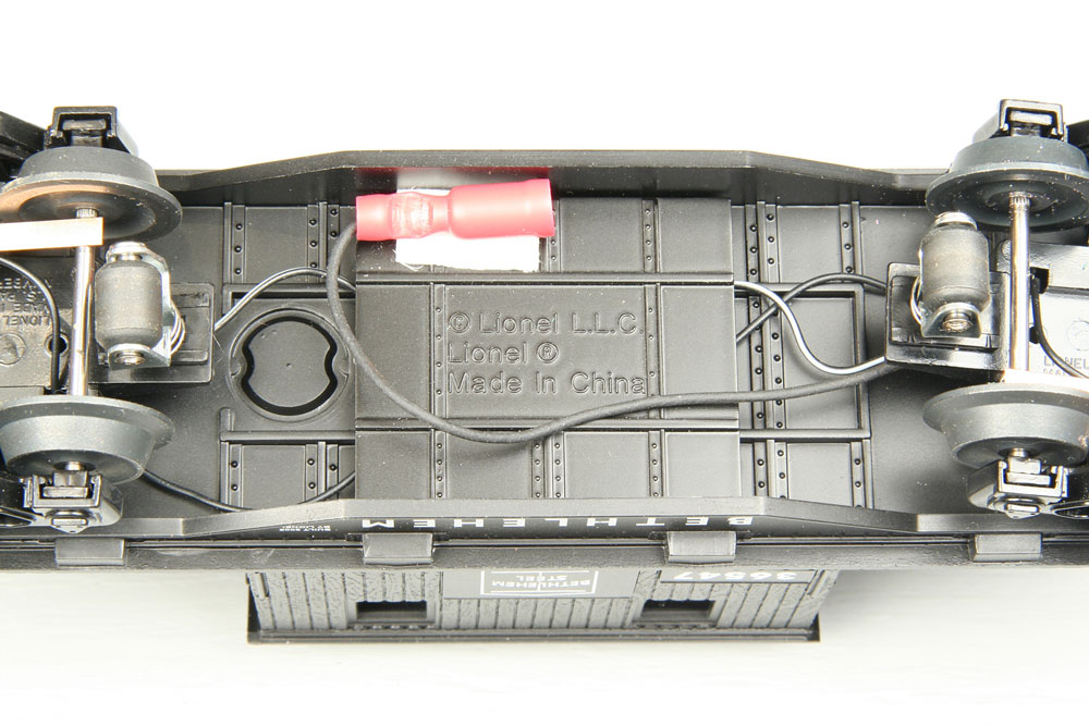
The underside of the locomotive reveals the problem. With its 8-inch roller spacing, the Lionel GP9 at top has no issues with trackwork. On the switcher, however, the two pickup rollers are just 3 3⁄8 inches apart and can’t span the middle of a double-slip switch or other long pieces of complex track. I decided to solve the problem simply and economically by connecting my locomotive’s motor to the pickup rollers on a lighted trail car, a matching Lionel Bethlehem Steel transfer caboose. Photo by Peter Riddle
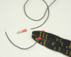
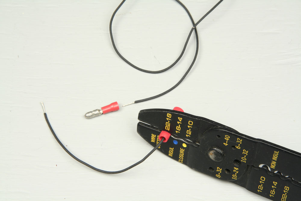
Make a two-piece wire harness from no. 22 or 24 flexible stranded wire. Make sure the wire is very flexible to negotiate curves. Cut two pieces, one just a few inches long and the other long enough to reach from the locomotive’s pickup rollers to the rollers on the caboose when they are coupled together. Crimp a male solderless connector to one end of the long wire, and a female connector to the short one. Photo by Peter Riddle
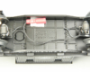
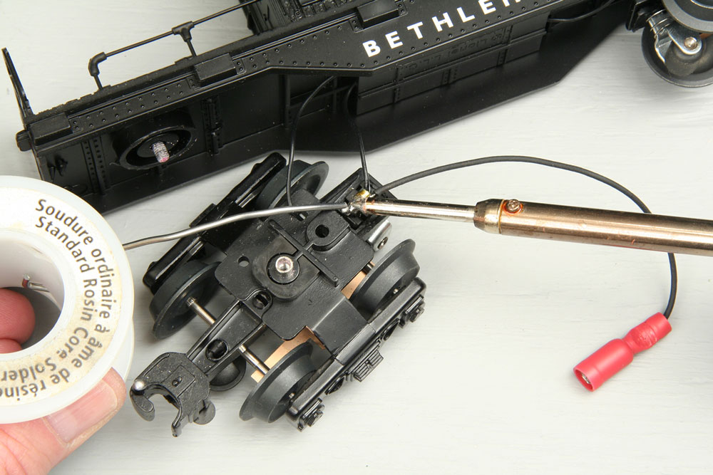
Unscrew one of the trucks from the caboose and solder the other end of the short wire to the metal bracket of the pickup roller. Be careful not to let the hot soldering iron touch the plastic parts of the truck frame, as they will melt. Photo by Peter Riddle
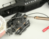
Reattach the truck and fasten the solderless connector to the underside of the caboose with double-sided tape, with the open end facing the locomotive. Place it behind the fishbelly sides so it will not show when the caboose is on the track. Photo by Peter Riddl
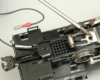
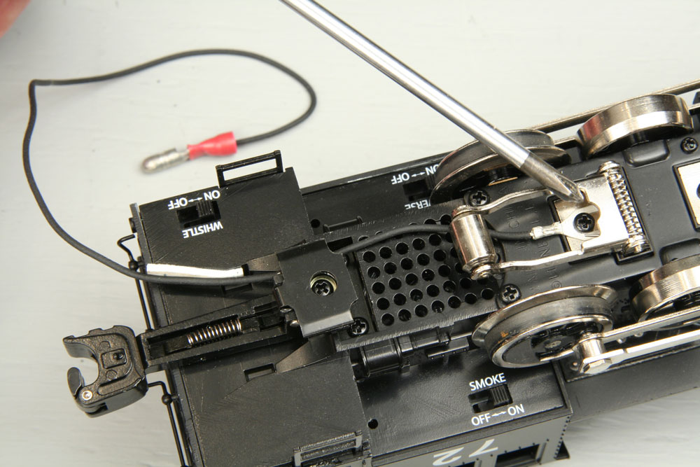
Crimp a small solderless spade lug on the end of the long wire and attach it to the screw that holds one of the pickup rollers to the underside of the locomotive, making sure the wire passes under the roller. Fasten it near the back of the locomotive with a small piece of double-sided tape. The tape should help keep the wire clear of the swinging rear coupler, allowing smooth coupler arm movement and preventing friction on the wire. Photo by Peter Riddle
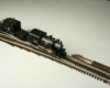
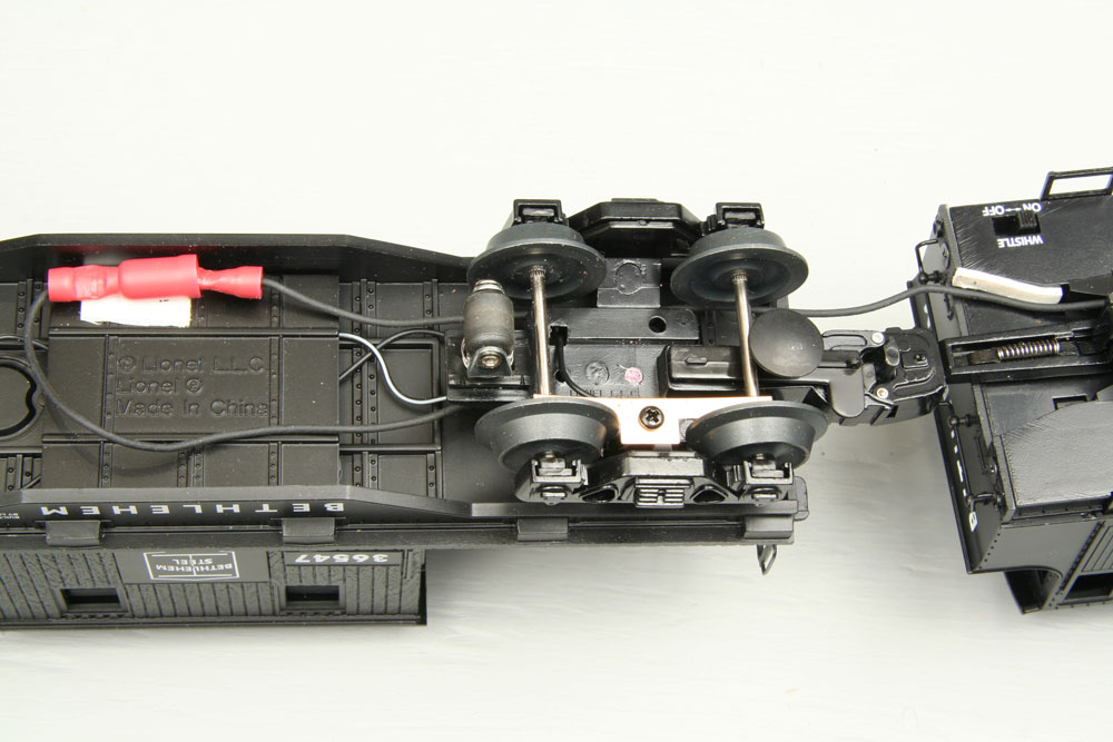
Couple the locomotive and caboose together and run the long wire between the front truck and the frame of the caboose. Push the solderless connectors together. Power will now transfer from the middle rail of the track to the motor through any of four pickup rollers, two on the locomotive and two on the caboose, over a span of 13 inches. This is a far greater separation than will be required by any piece of track. Photo by Peter Riddle
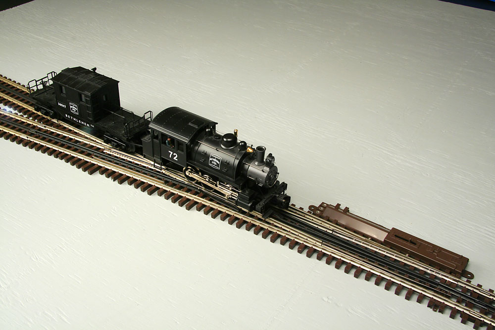
As long as this switcher is coupled to its transfer caboose, it will now negotiate long switches and crossings. You can use this trick with any small locomotive or motorized unit by mating it to a lighted caboose, bunk car, or piece of rolling stock such as a searchlight car. The switcher pushes much more often than it pulls, and the caboose just follows along. Photo by Peter Riddle
Supply list
22- or 24-gauge wire
Male and female solderless connectors
Crimp-on spade connector
Screwdriver
Soldering iron and solder
Two-sided tape
Wire cutter/crimper


Excellent idea. Thanks for sharing.
Great! This is the better way to have continuous connection.
This guy’s a genius….