Videos & Photos Videos How To Benchwork Canadian Canyons Series: Part 4 – Alignment pins and additions

Canadian Canyons Series: Part 4 – Alignment pins and additions

By Angela Cotey | March 20, 2017

| Last updated on November 20, 2020


Email Newsletter

Get the newest photos, videos, stories, and more from Trains.com brands. Sign-up for email today!

Having trouble viewing this video?   Please visit our Video FAQ page
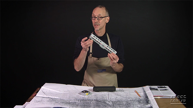
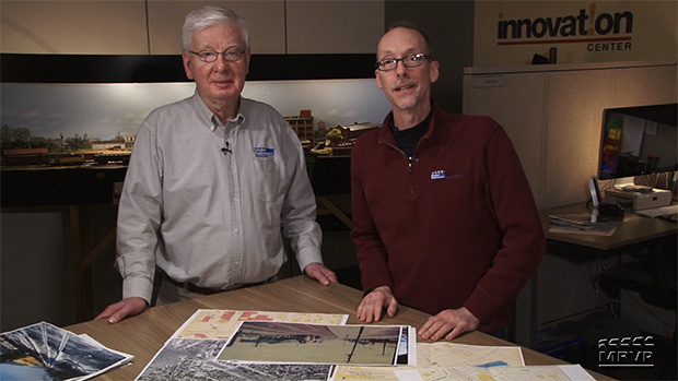
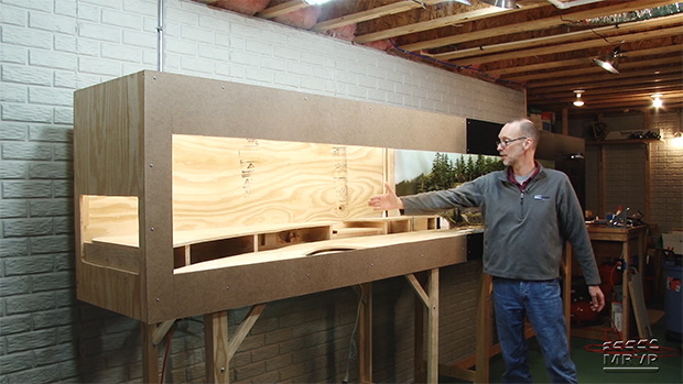
Connecting plates and frame sections are in place. Now watch as David shows how to install the steel alignment pins that make it possible to attach the removable section perfectly every time! As a bonus, David also shares a way to reinforce floppy fascia.

19 thoughts on “Canadian Canyons Series: Part 4 – Alignment pins and additions

  1. David love the series when putting screws in the pattern makers pins try using a Vix bit it fits in the counter sink centering the bit in the hole and the drill bit comes down through the center

  2. JUST WHAT I NEEDED!!! I’m a “newbie” to the hobby, building my first layout (The Alaska Railroad); I hope I haven’t bit off more than I can chew! Anyway, I am still in the process of building my bench work (HO scale). I have three big sections I will need to join together and match as perfectly as possible. I also placed my first set of legs right against the outside of the frame, not allowing for any “kick space”. OOPS! (An easy fix at this stage). A couple of ideas (from a total novice). My layout uses “L” girder legs. Instead of fixed castors, I have installed castors that mount with a threaded screw. I installed pieces of aluminum angle to the bottom of the legs and drilled a center hole. Now I can adjust the legs up and down to maintain level. Waddya think? Also, I happen to have a “T” square for sheetrock that works great for marking cuts on plywood sheets. I’m really looking forward to your video of building a helix (not sure yet, but maybe) since I’ll have some pretty tall mountains and at least one very tall trestle, like the one I actually rode over in AK on the narrow gauge at yellow pass.

  3. Don’t you need that angle on the bottom of the left side of the extension? Like you have on the top. Or the bottom of the fascia will flap.

  4. David;

    Enjoying this build very much, especially how you are dealing with the complex issues of differing heights of the benchwork on the various sections. I do have a question though. You cut a slot in the plate mounted on the main sub-roadbed section so you could access the helix. But you didn’t cut a corresponding slot in the other plate. Does that mean you will have to disconnect the two sections if you want to gain access to the helix through the slot that you cut? I would have thought you would need a slot in both plates that lined up so you could reach all the way through.

    Can’t wait to see how the helix is constructed. That will be interesting.

  5. Great content David! Okay, who was the wiseguy who set off the smoke detector in the middle of the video shoot?

  6. After watching this the first time and thought I had a question, I watch it a second time and found where you explained the procedure fully. Good work session… But be careful of the words you use… ‘Next time we’ll “dive” into putting the plywood’, thus triggering the alarm for your sub to ‘dive, dive, dive’… very funny!

  7. Hi David,

    funny that you had that problem with the end panel being at the wrong height (well not funny really), because when I watched the video before this one, I thought to myself as you were gluing and nailing it on “hmm, I might want to screw that on instead, just in case it is the wrong height, you can always unscrew it and adjust it, and later on glue it, once you’re 100% sure that it is in the right spot”. So how are you going to fix the top now that they are different heights for the two panels?

  8. Mark as I recall he makes marks on both sides so it looks like a mark. A random mark on the wood can sometimes be mistaken as your pencil mark. Don’t ask me how I know that.

  9. OK, What was that noise? Smoke alarm ? Fire drill ? Great video, and nice job using the small wafers of dowel for spacers .

  10. Well David, was the torpedo a hit or miss? I model HO scale and am finding your n scale Canadian Canyons Series very interesting. I’m in the planning stage of my “retirement” layout. The videos on the bench work thus far have been helpful. Thank you. I enjoy watching you explain what you are building. Looking forward to seeing the finished product. Blessings.

  11. When you sent Drew to Canada to train watch, did you do it in anticipation of making this layout or did his trip inspire you to do this layout?

  12. OK, good idea. Pattern makers pins are the answer (Where to buy them), but you already had pins, wood dowels, why not trust them? I would think if you did a good job that they would work fine. No? Too much opening and closing and getting sloppy?

  13. If you need to drill down to a particular depth, measure the depth on the drill and mark it with masking tape. It’s easy to see and less riskier than guesswork. Great series David and great work. Looking forward to all of it.

  14. I thought I had asked this question previously; however, it never got posted. That is: Why do you make marks on both sides of the tape measure?

  15. Pattern makers use the pip on the dowel half to mark the position on one side of the pattern.

  16. It’s amazing to me that these locating pins are only available from Great Britain. There are other forms of bullet pin but nothing that is attached with screws

  17. David, hope you’re not over engineering this layout. Would have thought 3/8″ wood dowels on 12″ centers would have done the trick. No matter which method, they do have to be aligned. Think you would have to reinforce the plate as you did, only adding reinforcements where necessary. I know, I know, the dowels could be broken from rough handling.

You must login to submit a comment