


Once we had the L-girders built, it was time to turn our attention to adding the legs and support bracing for the layout. We constructed the legs as simple subassemblies with their own cross bracing. It all bolts to the L-girder frames using ¼” carriage bolts, wing nuts, and washers.
We used more dimensional lumber for these parts, including 2 x 2s for the legs, 1 x 4 boards for the bottom leg connectors, and 1 x 2s for all of the angle bracing. In addition, we included adjustable furniture glides at the base of the 2 x 2s, so we could level the layout on uneven surfaces.
Choosing a layout height
Before beginning construction of the leg components, we first determined the height we wanted our layout to be. There is no one-size-fits-all decision for layout height. Probably the biggest contributing factor is the height of the individual or individuals that will use it. Tall people will prefer tall model railroads, and likewise shorter individuals will prefer shorter layouts. The important consideration is comfort: How easy is it for you to work on the railroad and run trains comfortably? Does it stress your back to work on the railroad for long periods of time? Can you work under the railroad easily? These are all good things to consider.
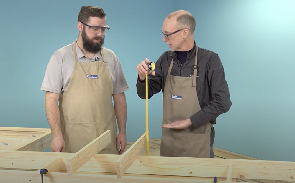
Bryson and I conducted a simple test to determine the height for the East Troy Industrial Park by setting one of the frames on our adjustable height workbenches. We then raised and lowered the bench to various heights, testing things such as reach and viewing angle, until we settled on something that worked well for us.
Most of the staff, the layout’s primary users, are 6-foot or taller. We found that with legs that set the top of the L-girder frame 40” from the floor, once we added the joists, risers, and subroadbed to the top of it, our finished height would be around 45” from the ground. That seemed to work well for us, so we chose 40” as the length of the legs.
Leg position
Next, we determined the position of the legs under the layout. The L-girders would allow us to put the legs at each end of the frame without concern that it might sag. If we were building a permanent layout, that arrangement would permit us to use the fewest number of legs possible, as successive sections could connect to the previous one, requiring just a single pair of legs on the opposite end for each successive frame. As such, we could support our 14 x 19-foot layout with just 4 pairs of legs, which would leave considerable open space under the railroad.
However, our layout needed to be portable, and its three sections needed to be self-supporting as well for making videos. Therefore, each section would require two pairs of legs.
Leg position on a layout can also matter, particularly where people’s feet are concerned. If a leg is mounted along the front edge of the benchwork, it runs the risk of being kicked when one stands close to the railroad. This can jar scenery and derail trains, not to mention that it doesn’t feel good on the toes.
For the East Troy project, we placed the legs 6” or more from all visible edges of the railroad, allowing for plenty of toe space while still supplying stable support. To keep the legs from clustering under the railroad, we also placed them 3 feet from the ends where sections connect to each other as well.
Building pairs
We built the legs in pairs, connecting two 40” 2 x 2s with a 1 x 4 crossmember near the base.
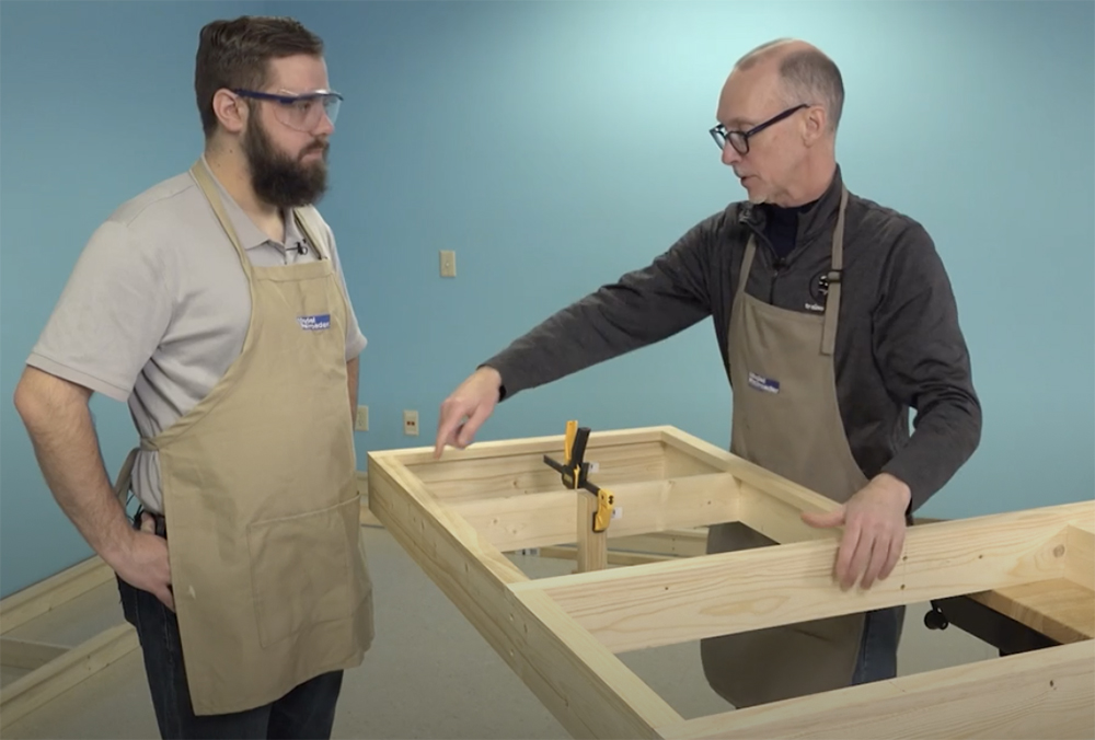
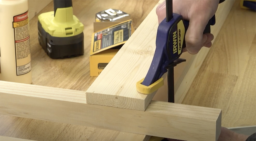
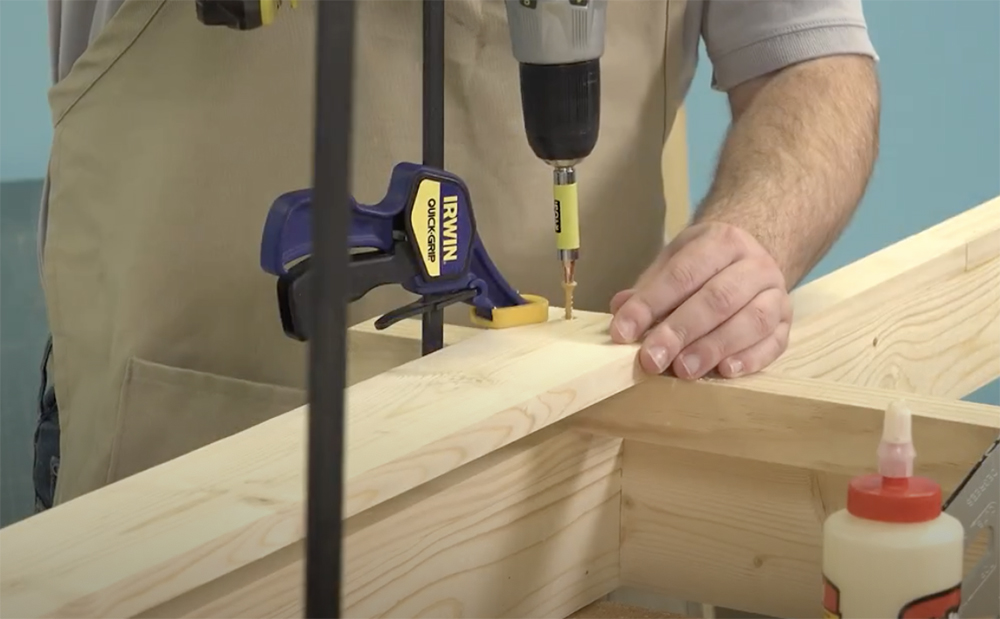
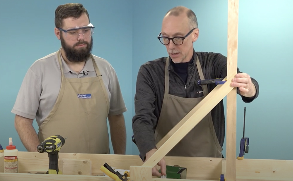
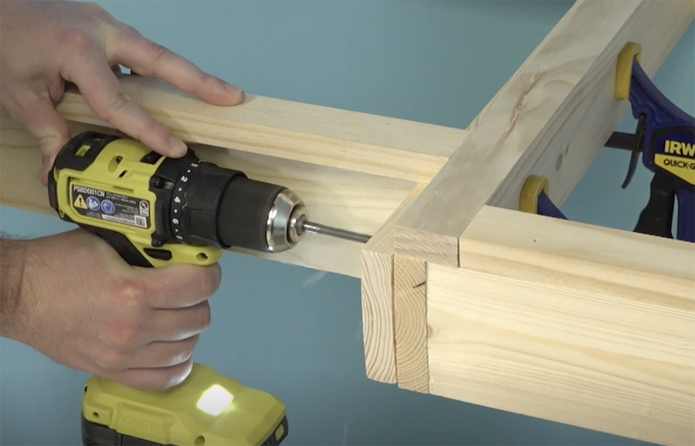
As shown in the next two photos, the L-girder frames proved to be a perfect working surface for leg construction, as the 1 x 2 flange on the girder made it easy to clamp the leg components together and hold them in position for assembly.
After cutting the parts for a pair of legs, we glued and clamped the 1 x 4 crossmember 4” from the bottom and flush at the outer edge of both legs. We then used a square to make sure the parts were aligned, and we doublechecked the measurement at the top of the legs for proper spacing. We then drilled the pieces and installed 1-5/8” deck screws.
Adjustable feet
With the leg pairs complete, we next installed adjustable feet in them. We’ve used casters on previous layouts to easily move them around our workshop space, but in this case, once complete, this layout will live in a large storage room that connects to the shop, so casters aren’t necessary here.
While we could just let the bare wood legs stand on the floor by themselves, the concrete floor in our building has a lot of uneven spots – and if you’re working in a basement or a garage, you’ll likely have the same problem. To solve this, I purchased some adjustable 1” furniture feet and installed them in the base of the legs.
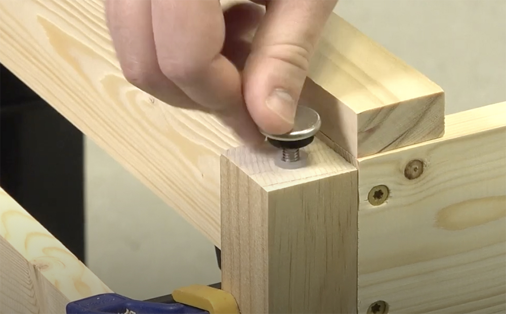
The feet come with two pieces; a foot with threaded rod attached to it and a nylon threaded socket.
Installing a foot is easy. The package lists the size of drill required to make the hole for the socket. Drill the appropriate hole about 1” deep straight into the bottom of the leg. Next, tap the nylon socket into the hole with a hammer and thread the foot in place. The glide gives you about 3/8” of adjustment, which is typically enough for most floors. However, in one particular area in our workshop, I did need to slip a small shim under the glide to make up the difference.
Attaching legs
With the adjustable glides on the feet, it’s time to attach the legs to the frames. Work with one pair of legs at a time. Position the legs on their marks, clamp them to the frame, then drill the ¼” holes for the carriage bolts. We put two bolts in each leg, and we positioned them 1-1/2”” apart, allowing us sufficient room for the wing nuts to pass each other while tightening them.
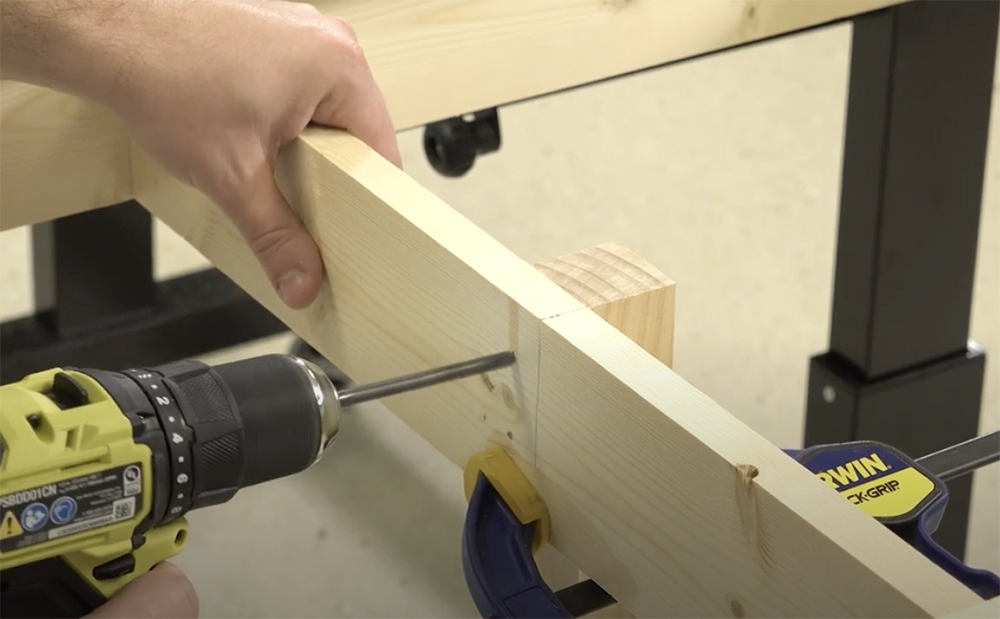
Once the holes are drilled, insert one ¼” x 3” carriage bolt into the top hole for both legs, then add the washer and wing nut. Don’t over-tighten the wing nut; you want the leg to hold firm but also be able to adjust it yet if needed.
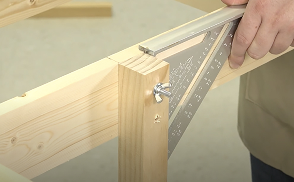
Next, working on one leg at a time, adjust it using a square; it needs to be at a 90-degree angle to the frame. Once you are satisfied with its position, insert the second carriage bolt and tighten the wing nuts for both bolts completely. Repeat this step for the other legs.
Leg braces
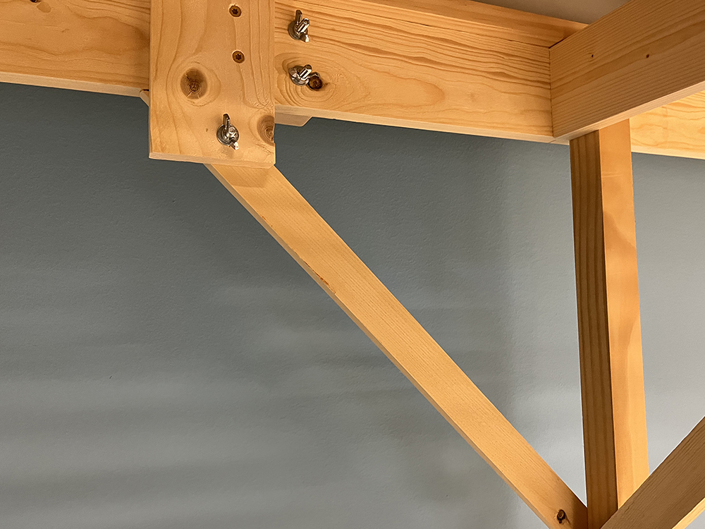
Angle braces are an easy way to remove any and all wobble from your benchwork. We used a couple of types of braces on our East Troy layout, making them from 1 x 2s. The first ones we installed were short braces that lock the legs to the frames at a 90-degree angle.
While you can make angle braces any length you choose, I made ours 24” with a 45-degree angle cut into each end. At 24”, I can get four braces from a single 8-foot board, so that’s why I chose that dimension. If you have a miter saw, cutting the angles is easy, just make sure your angles face in towards each other on the finished brace.
Before installing the braces, I needed to add a connecting plate so that they could bolt to the frame and be removed easily. I cut 5” blocks of 1 x 4 from leftover scraps for this. You’ll need one for each leg brace you plan to install.
With the braces and connector blocks cut, Bryson and I set the first layout frame upside down on the workbench with its legs pointed up. We then positioned and clamped the two braces for this leg pair in place. With the 45-degree angles cut into the legs, it’s pretty easy to align them by eye, however, if you want to measure it for accuracy, the tip of the brace measures 16-3/4” down the leg from the bottom of the frame.
Next, attach the 1 x 4 connector blocks to the girder. The far edge of the block measures 15” from the inside edge of the leg. If you have the time, you can simply glue the block and clamp it in place until the glue dries. However, since we do most every project for video, we also secured the block to the frame with 1-1/4” deck screws, allowing us to keep assembling the layout sections even while the glue was drying.
After installing the connector blocks, check to make sure the leg is still square and vertical, then drill the braces for ¼” carriage bolts. We used 2” bolts where the brace connects to the 1 x 4 block, but we needed 3” bolts for the leg connection. You will need just one bolt in each location. Complete the connection with ¼” washers and wingnuts.
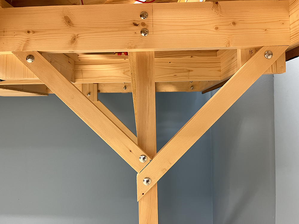
Being L-shaped, each layout frame section has a narrow pair of legs and a wide pair of legs. We were able to position the narrow legs next to a crossmember on the frame about 3 feet from the end. This allowed us to place both legs into corners for a solid fit, and each leg needed just one angle brace. The wide legs, however, had to be positioned in the middle of the frame to prevent the leg from being easily kicked from the three exposed sides.
With no suitable corner to make the same kind of connection as the narrow legs, we had to do something a bit different here. On one of the two legs in the wide pair, we added a second angle to brace the leg from the opposite direction. As shown in the photo, this brace needed to be modified to fit, having a square end that attaches to the leg so it would fit next to the second brace. It also received its own 1 x 4 connecting block. In all other respects, it is attached to the leg and the layout the same way as the other braces. The wide pair of legs proved to be stable with just the single additional brace.
Anti-sway braces
After completing the legs and braces, we then worked on other aspects of the layout, including adding the backdrop, which we will talk about in the next installment of this series, as well as the joists, risers, and plywood subroadbed. However, as we worked on the layout, we discovered that it could sway laterally if you leaned on it. This was a development I was unfamiliar with from previous project railroads.
Normally, as constructed, the layout’s frame and leg assemblies should have been very solid. Looking back at the Winston-Salem Southbound layout, which used the same L-girder frame construction, I discovered that the only thing I’d done differently on that design was to add a second, 1 x 4 crossmember at the top of the leg pairs. As it turned out, that crossmember prevented the sway I was experiencing here.
As an easy fix, Bryson and I cut up some leftover 1 x 2s we had from building the benchwork and made a few anti-sway angle braces. These were glued and screwed between the top and bottom of the leg pairs. After adding them to a single layout section, the lateral sway was eliminated immediately, but as a precaution, all leg pairs got one.
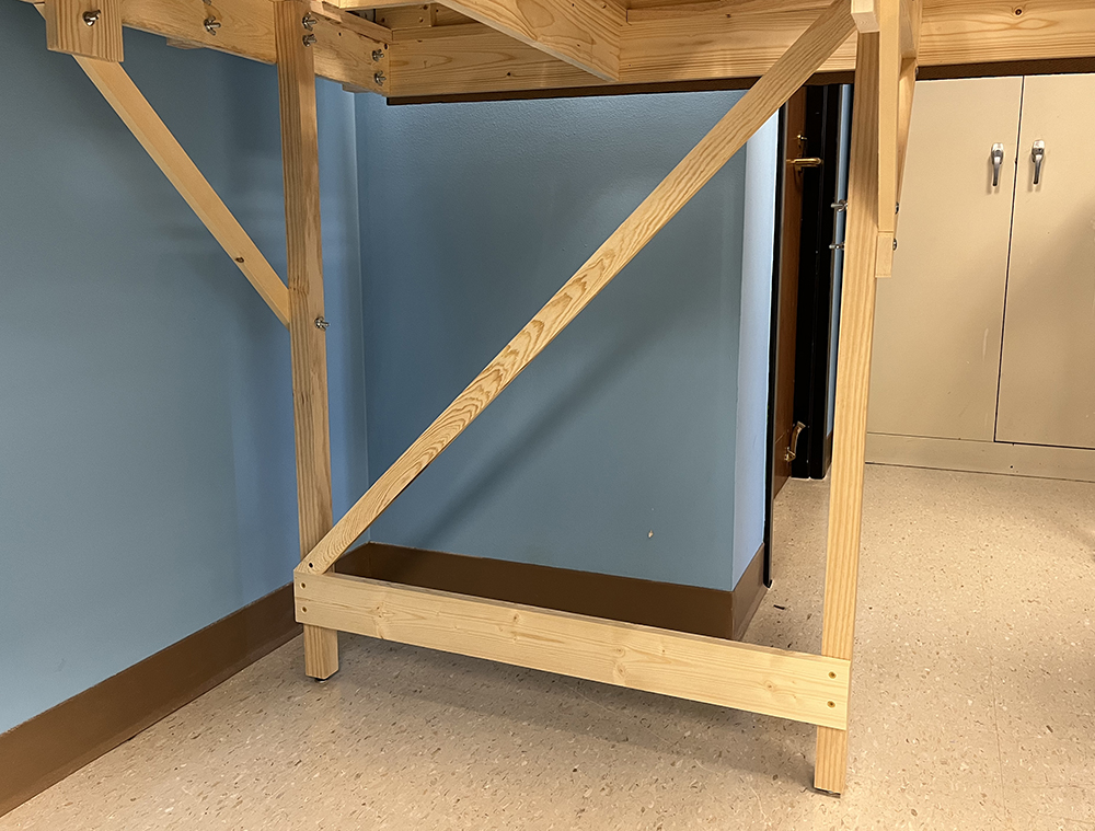
Personally, I don’t like how they look, which is why I used the 1 x 4 across the top on the previous layouts; It produces a cleaner leg design. However, we plan to cover the legs and everything else under this layout anyway with black curtains we saved from the Milwaukee, Racine & Troy, so eventually, the bracing won’t be visible.
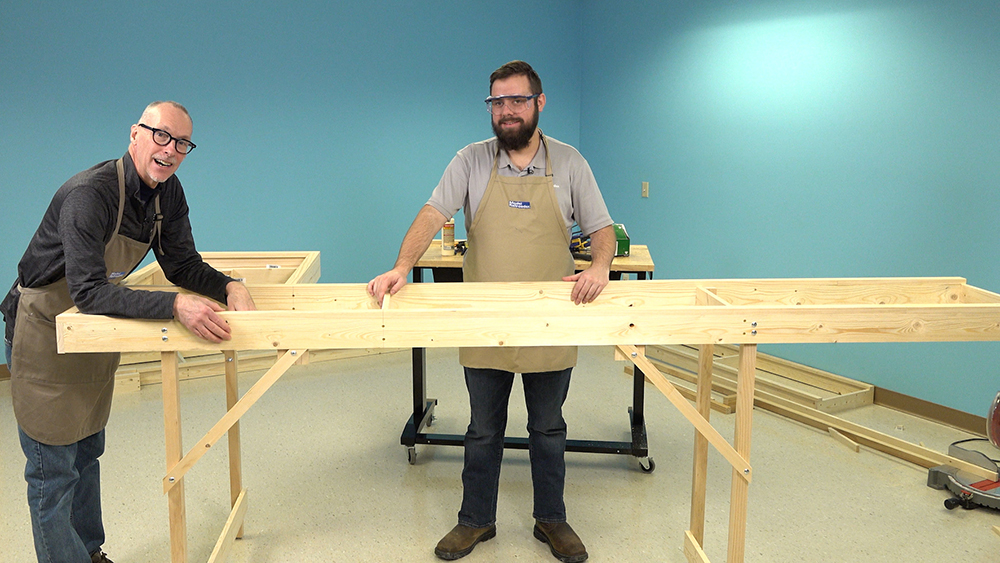
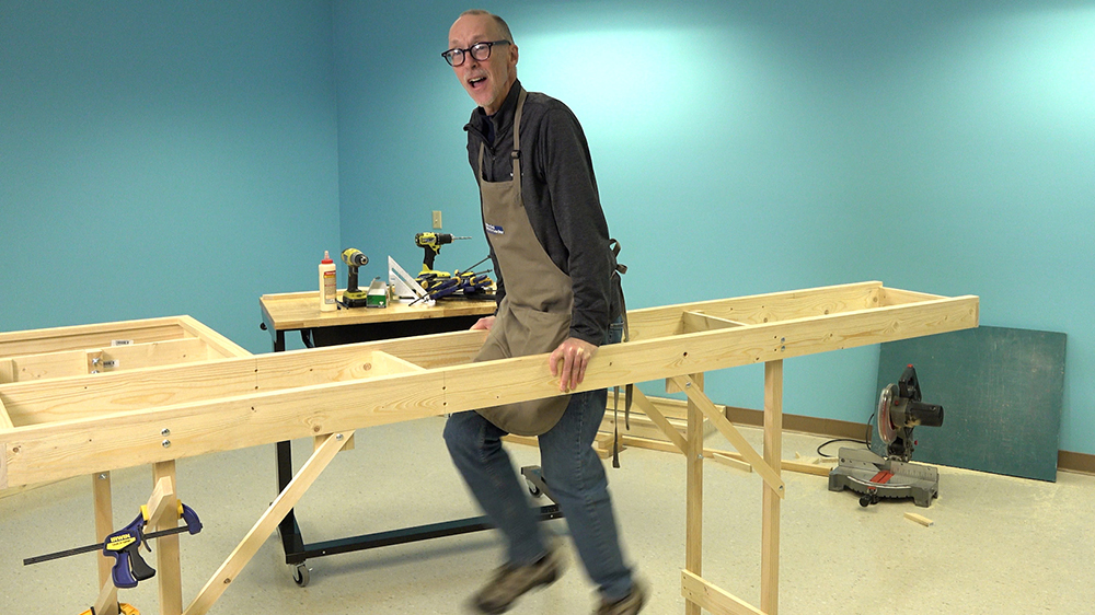
How strong is the finished L-girder and leg construction? We’ll it will hold considerable weight – at least 170 pounds worth anyway. As shown in the photo, one frame section on its four legs held me just fine without flexing at all.
Attaching the sections
Once we had the sections on their legs, Bryson and I arranged them in the proper order in the room and then bolted them together. We drilled two holes between each section and secured them with ¼” x 2” carriage bolts. Again, we used wingnuts to allow us to easily separate the layout pieces for filming and for moving.
While it’s exciting to see the railroad at this stage, it really doesn’t look like much yet other than open frames on legs. But that’s ok, since even building the benchwork is all part of the fun. Speaking of work, we’ve got a lot more ahead of us, and we’ll tackle installing backdrops in the next part of this series.
Click here to read the previous article in the East Troy Industrial Park series on Trains.com.
Click here to read the next article in the East Troy Industrial Park series on Trains.com.
Click here to watch the construction of the East Troy Industrial Park on Trains.com Video.
Click here to watch the Model Railroader workshop webcam on Trains.com Video.


great