One of the beautiful things about 3D printing technology is that you can easily make custom parts. This let’s you standout from other layouts plus it is a lot of fun, but it can be frustrating at the same time. First, let’s make a simple part that everyone needs; wheels.
I am going to start with the wheel design published in Garden Railways December 2018 issue by Mike Lafond. Download a free copy of that article.
Onshape (www.onshape.com) is a free graphical design tool that is very similar to SolidWorks. I have discussed how to sign in and some of the features that Onshape has in previous columns. Therefore, I will not be starting from the very beginning, but start with the design. Refer to these columns for more information:
Part 13: Build a modern-style water tower
Part 14: Build the middle sections of a water tower
Part 15: Build the top section of a water tower
Part 16: Finish the water tower
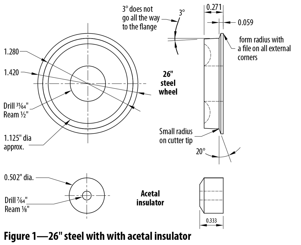
Figure 1 shows the wheel and the accessories for a 26” wheel. We will be creating the wheel by drawing a side view silhouette then rotating around an axis to create the wheel.
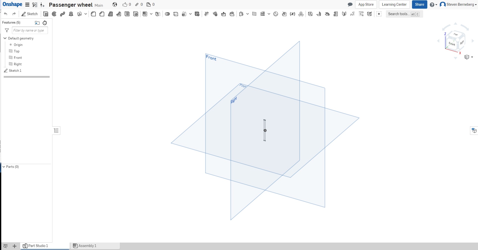
When you create a document the front, right and top planes will be shown.
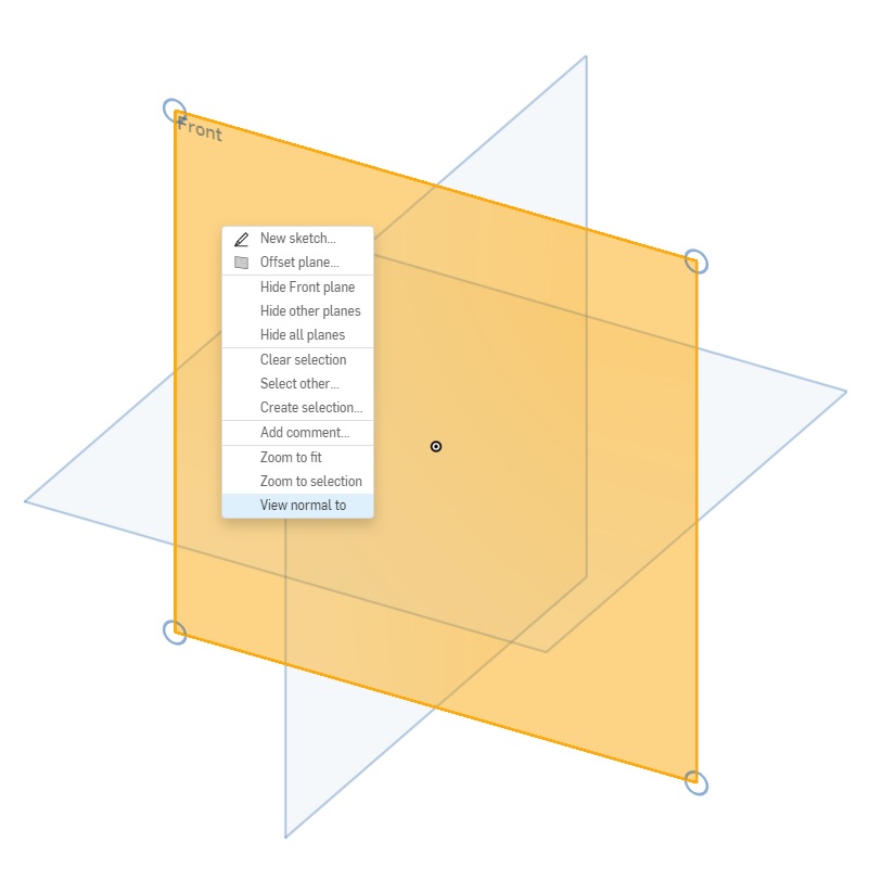
For this document I am going to highlight the front plane and right click. A drop down menu will be shown and select “View normal to”. This will be the plane that we will create our sketch on.
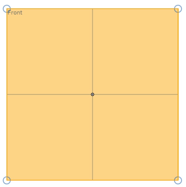
This is what you should see now.
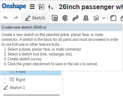
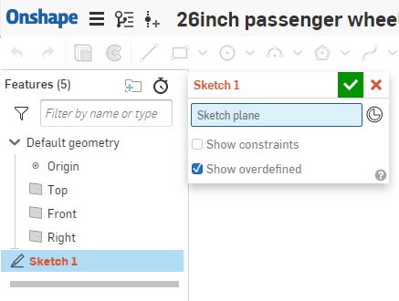
Now we have to create a sketch on the Front plane. To do that, locate the “Sketch” icon in the upper left hand of the screen in the toolbar. One thing you will notice is that if you “hover” your mouse pointer over the icon it will give you some help. Click on the “Sketch” icon.
Now a dialog box pops up with some information that is still needed. If I had selected the front plane before creating the sketch, the blue box with the sketch plane in it would show the front plane. Since I did not select the front plane before creating the sketch, click on the front plane. The front plane should now show in the dialog box. Do not use “Show constraints” at this time. While helpful for some sketches, it can also create a lot of problems.
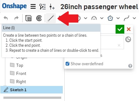
Since we are going to revolve the sketch to get the full wheel, a revolve axis is needed. To make things easy, we will add a line along the “Top Plane Axis”. But first, we need to know how to draw a line. As the help box says, click the start point, click the end point.
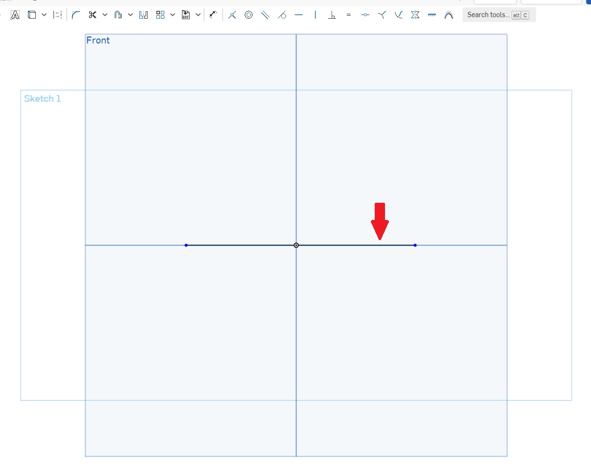
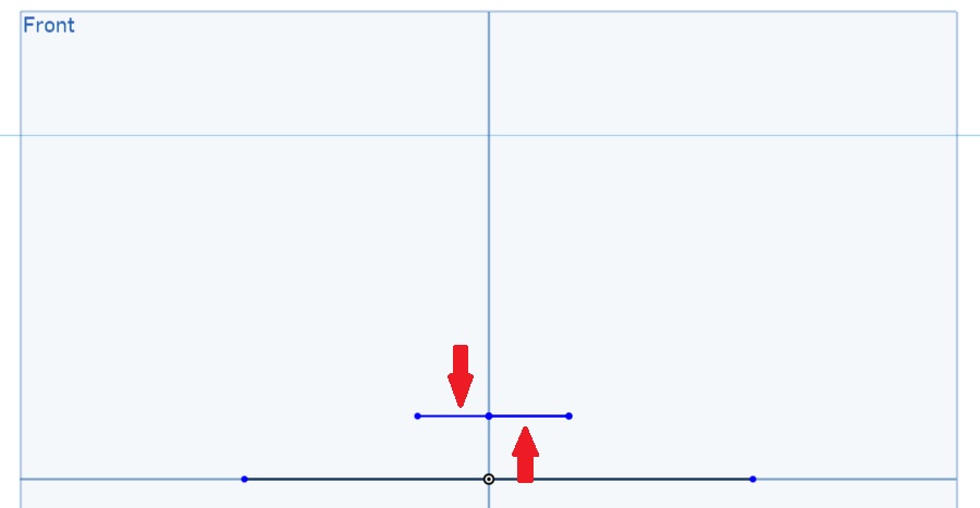
Here I have drawn our rotation axis line along the top plane.
Now we can start to draw the silhouette. We will need to refer to figure 1 often. The first thing we need to do is draw a line that outlines the hole where the acetal insulator goes. Remember though, we are only going to do half of the hold size because we will revolve through the other half. We can make these lines around the correct length because we will make them exact in the next step.
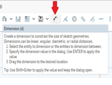
Now we can make them the correct size by using the dimension icon. Click on the dimension icon and prepare to make the lines the correct length and the correct distance from the revolve axis.
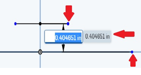
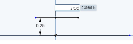
If you look at the picture to the right, you will see red arrows pointing to two blue dots on the lines. One is at the end of the revolve axis and one is at the end of the line on the insulator line. Click on those two blue dots. You will notice that the measurement tool shows the linear distance from the two dots. Slide your mouse to the left and you should get the distance between the two lines.
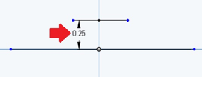
You will notice that the number is blue. That means the software is ready to accept your input. In this case we can either enter 0.25 or 0.5/2. It will do the calculations for you which is really handy sometimes. You will also notice that since both lines are considered coincident by the middle dot, both lines will move the correct distance.
Now we have to make the lines the correct lengths. You can click on the line or click on the two end points. This should look like the diagram. Notice that I did 0.271/2. I didn’t want to do it in my head so I let the software do the work.
If you click on the two very end points of the line, you can enter 0.271, but the line will not be centered. It will still work, but as an engineer, that makes my head hurt.
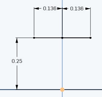
So we should have the following:
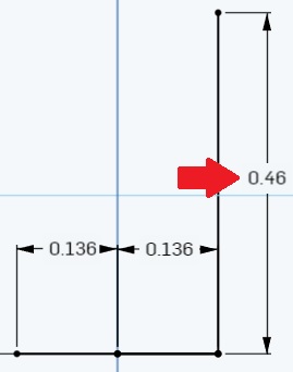
Now I am going to add the backside of the wheel. I go to the line icon and draw a line up from the right side blue dot to an arbitrary point that is vertical. Now I go to the dimension icon and click on the line that I just drew. We know that we only want half the length since we will be revolving the part so that is 1.42/2. Next we have to account for the acetal hole: 1.42/2-.25. That is the formula that I entered and the software does the math for me.
The path that I am taking in the drawing, adding the lines in the manner that I am, is because there are some unknowns in the drawing. That is OK because by using the known dimensions, I can kind of figure out the unknowns.
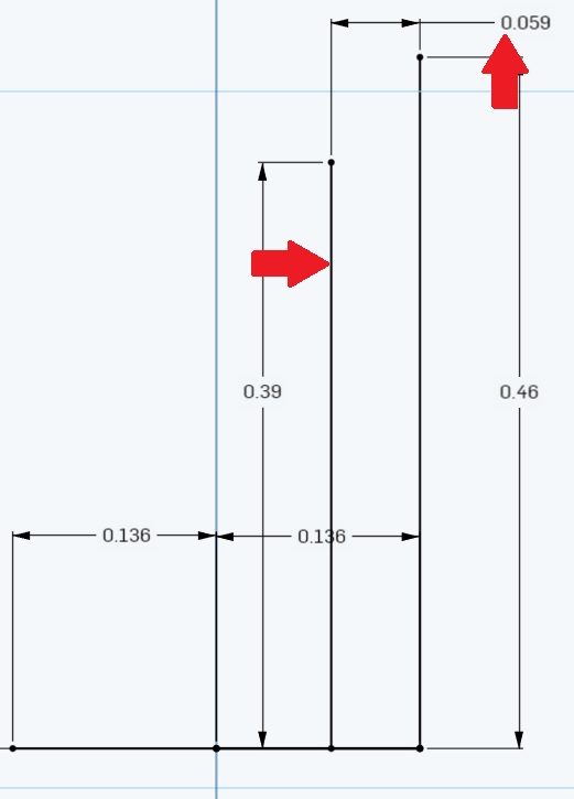
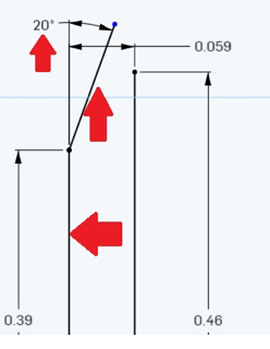
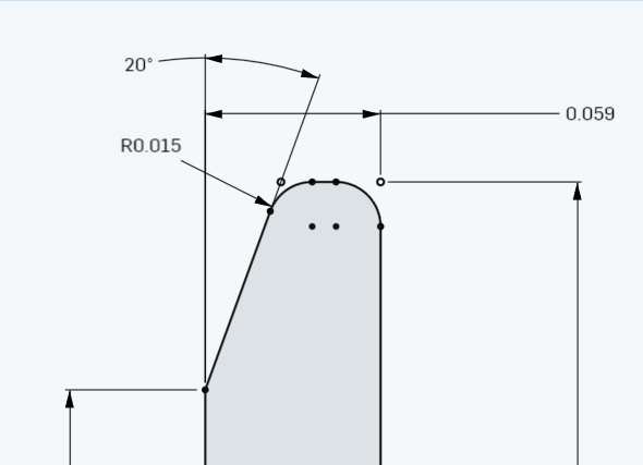
Next I am going to add the edge where the wheel meets the flange. This dimension is 1.28/2-.25. Then it must be set back from the rear of the flange by 0.059.
From the flange we must generate a 20 degree line as shown in Figure 1. First I am going to the line icon and putting a line from the lower flange line up and to the right. Don’t worry about the length or the exact angle. Once you have put in that line, the angle is 20 degrees. Do this by going to the dimension icon and click on the flange line. You will see a dimension come up. Don’t worry, click on the line that you just generated and you will see the angle measurement come up.
(Note: You might have to push the mouse up above the flange line to get the correct angle measurement.) Enter 20. This is what you should see.
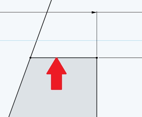
Now make a straight, horizontal line from the rear wheel line to the 20 degree angle line. The wheel will now turn a grayish color. That is because this is now a closed surface. But we have more to do.
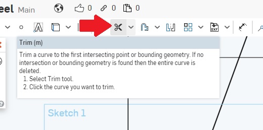
You can see a dangling line off the 20 degree line. That must go. To remove it we will use the trim icon.
Just click on the trim icon and select the hanging line. Now it is gone.
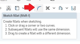
n Mike’s article, he says to “form radius with a file on all external corners.” To do that we are going to use the fillet tool.
Click on the fillet tool icon and click on the 20 degree angle line and the top horizontal line that we made earlier. Double click on the dimension and enter a small number like 0.015. Do the same for the other edge and you should see:
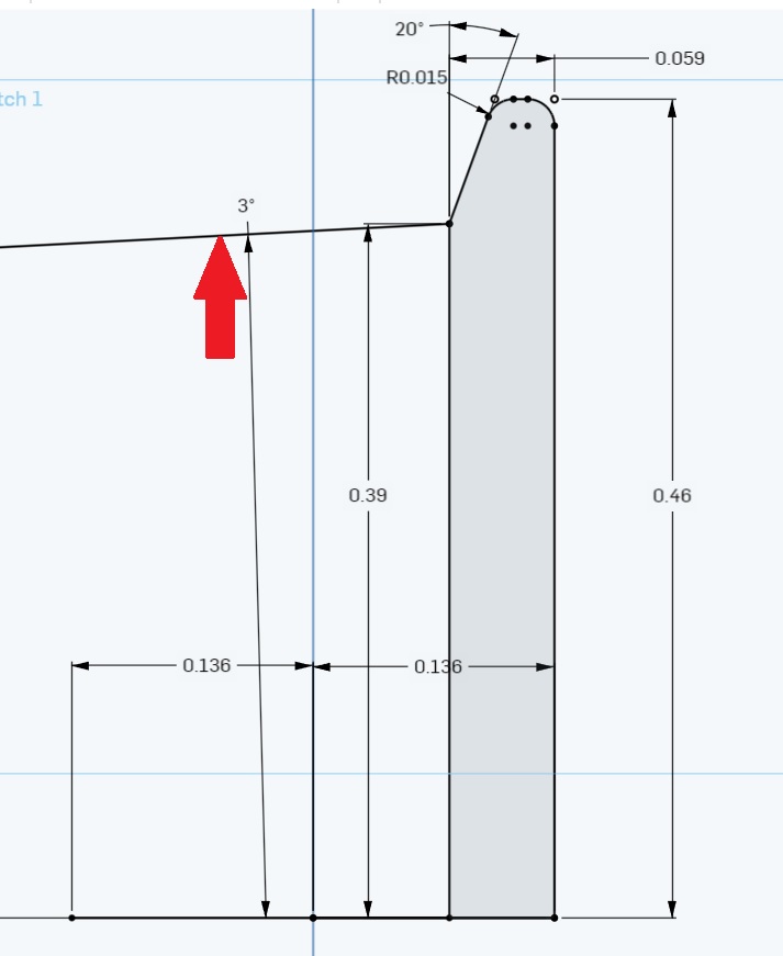
Now draw a line from the intersection of the 20 degree line out left and slightly depressed for the 3 degree line. Dimension at 3 degrees.
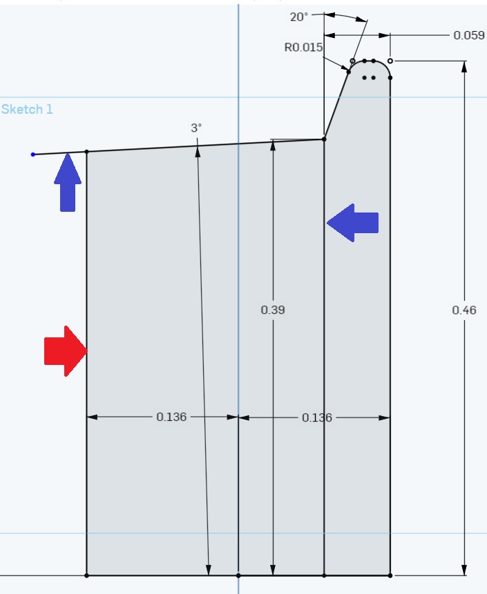
Almost done! Front face is next. Create a line from the acetal insulator line up to the 3 degree line as shown. You will see that now everything is grayed out and that is a good sign. If it is not grayed out you have missed a connection somewhere.
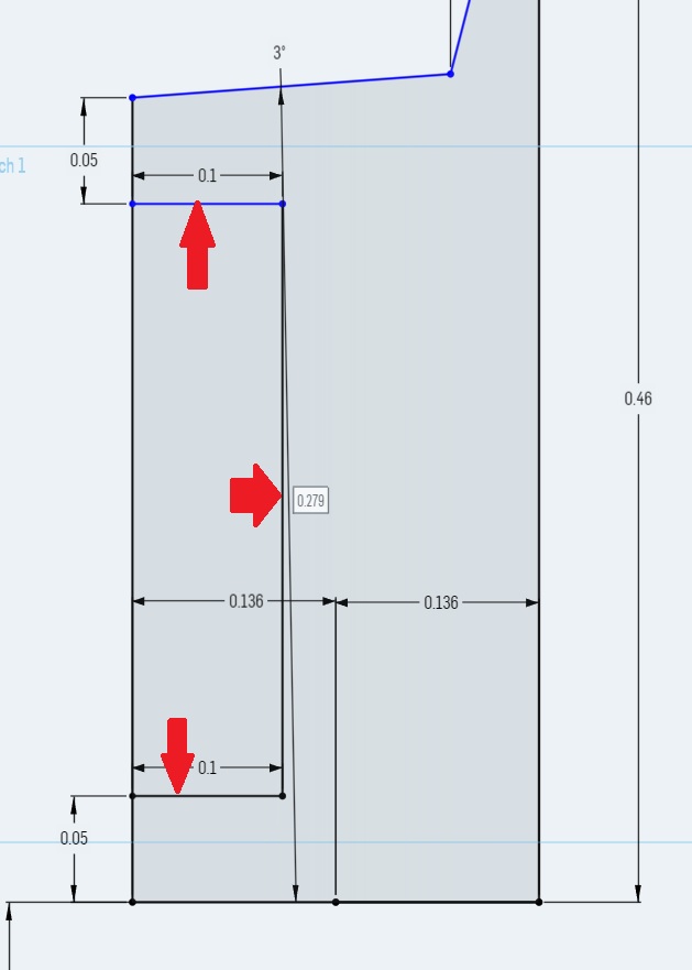
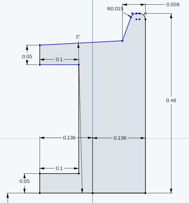
The Blue lines are lines that need to be trimmed. We do not want those. We need to create depressions as shown in Figure 1 to lighten the wheel. Since there are no dimensions, we are just going to “wing it”. I created three lines. The first two are 0.1 inches long into the wheel and down/up 0.05 from the edges as shown.
I have added those three lines indicted by the red arrows. Now select the trim icon and cut the line on the left between the lines pointed to by the up and down red arrows. Now you can see the cutout area in the next picture.
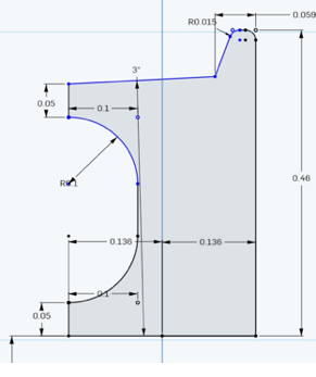
We will have to soften the edges. Again we will use the fillet icon.
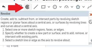
Now comes the most exciting of times: we are going to revolve the sketch to finish the wheel. Here is the revolve icon and the associated help screen.
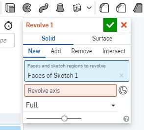
Now to revolve the part. Clicking the revolve icon we get:
In the blue dialog box you will see that the “Faces of Sketch 1” has already been selected. The faces should be outlined in beige. Next in the red dialog box we have to click on the box and select the “Revolve axis” that was the very first line we created.
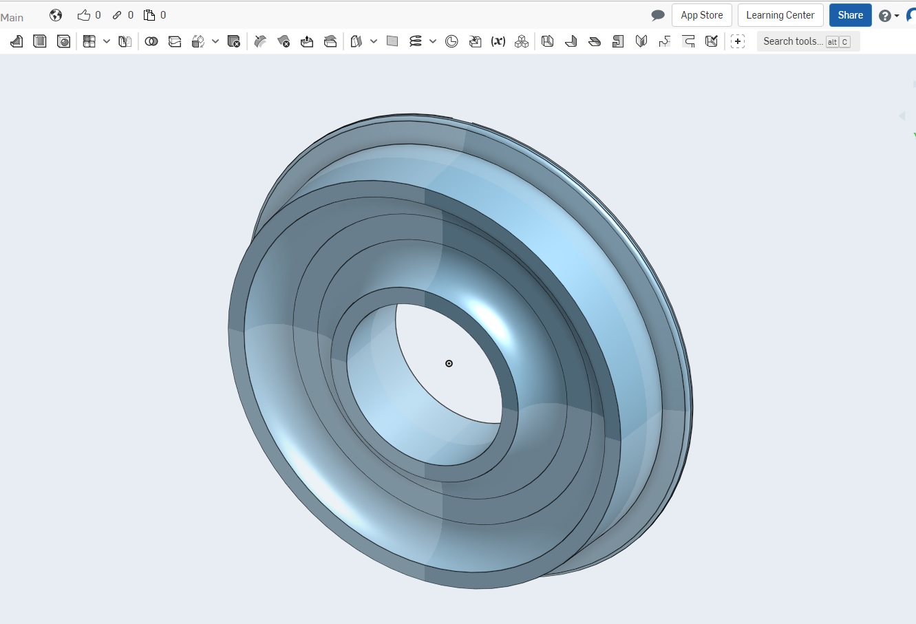
Once we do that the magic happens. We have a wheel.
Now you just have to make the acetal insulator. Now we could have made the insulator an integral part of the design, but I have plans for this part. If any of you attended my talks at the National Conventions, you might already know what I am going to do.
Summary
This was a quick introduction to Onshape. I hope that you have found it useful and it inspires you to develop your own custom parts. I intend to continue using Onshape and teaching some more of the utilities found in this software. But next time I will fill you in on what I intend to do with the 3D printed wheel. I will be using PLA which might give another hint.