How To Projects High-tech modeling for garden railroaders

High-tech modeling for garden railroaders

By Steve Berneberg | April 20, 2018

| Last updated on November 3, 2020

Part 14: Build the middle sections of a modern-style water tower

Email Newsletter

Get the newest photos, videos, stories, and more from Trains.com brands. Sign-up for email today!

01_Berneberg
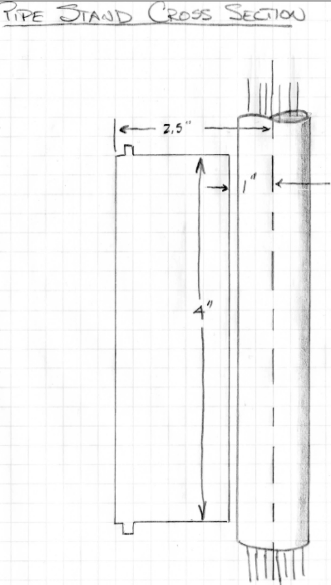
Photo 1
In my last article, I worked on the base of the water tower. Even with all the precautions that I took to keep warping to a minimum, it still warped and cracked. I’ll continue with this project by building the middle sections of the water tower.

OnShape review
OnShape is a 3D CAD tool that is free to hobbyists. The people who helped develop the famous SolidWorks CAD tool decided to go off on their own and develop a new CAD tool that is like SolidWorks. (https://www.onshape.com) You will have to register to use the product. The only possible downside is that if you use the free service, your files are shared amongst the community. If you want to keep your files hidden, you will have to upgrade to the professional package, which runs $125/month, billed annually.

Water tower middle section
Here is the sketch I made of the pipe-stand middle section (photo 1).

NOTE: We will be dealing with two different units of measurement; while OnShape can use metric or imperial, the 3D printer uses only metric. (There is an exception but I will not get into it at this time.) My work-around is to use imperial measurements on my drawings, then multiply them by 25.4, which is the conversion from inches to millimeters. You will see this during the drawing stage when developing the measurements on the drawing.

02_WorkspaceUnits
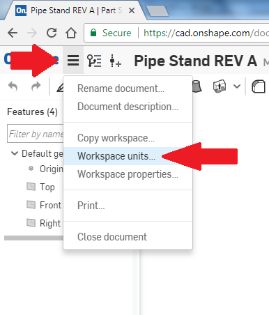
Photo 2
03_WorkspaceUnitsSelection
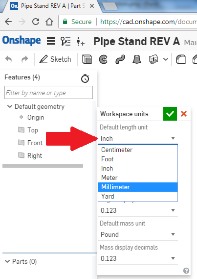
Photo 3
I have learned some new things about OnShape.  First, set the dimensional units to millimeters. You can still input everything in inches, just remember to multiply inches by 25.4. Following the pictures below, first left-click on the “triple horizontal bars,” shown by the top red arrow, and you will get the pull-down shown as in Photo 2. Left-click on “Workspace units…” to get to what is shown in Photo 3. Here you can set all sorts of units, but we are only concerned with dimension. Use the pull-down and select “millimeter,” then left-click the green-boxed check mark. Now everything you need to input is in the millimeters, which is what most of the 3D printers use.
04_Onshapestartingscreen
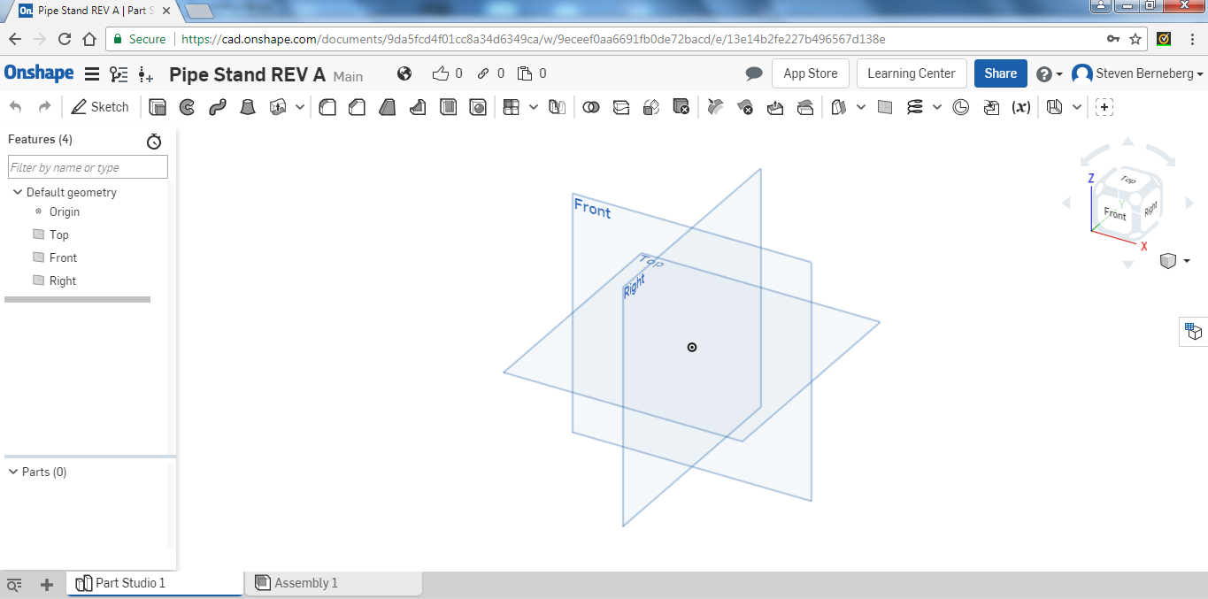
Photo 4
05_Sketchicon
Photo 5
Start the part

As before, the first thing to do is to align a plane. This way we will work on only one plane for now. Click on the “Top” lettering on the isometric cube. THERE IS NOT A RED ARROW ON THIS DRAWING. After clicking on the “Top” you should see only the Top plane shown in Photo 4.

For those of you who might have forgotten, the first thing we want to do is to create a sketch. Do that by left-clicking on the “Sketch” icon, top-left, as shown in Photo 5.

06_Selectsketchplane
Photo 6
07_Topplaneselected
Photo 7
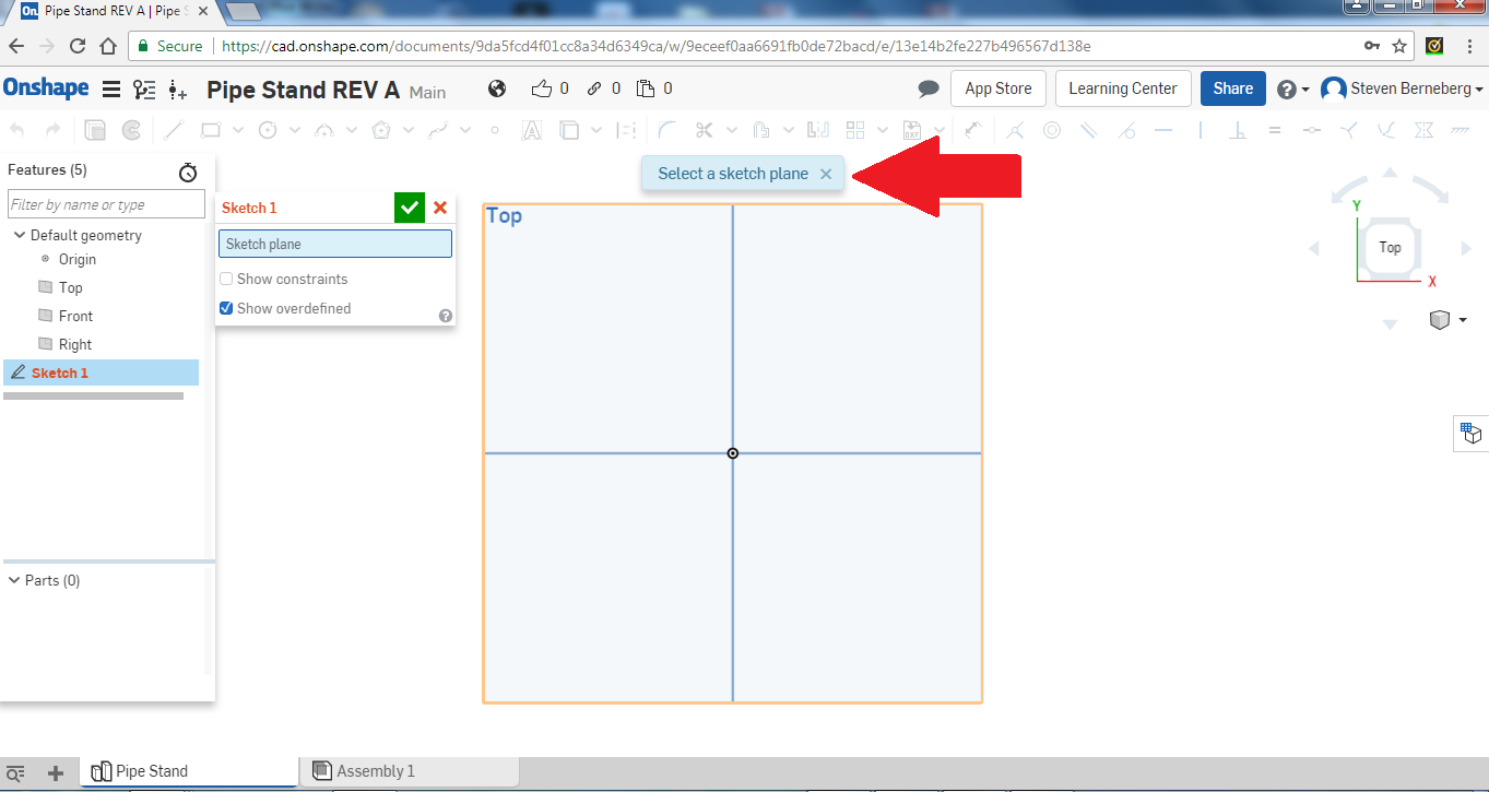
We are then instructed to select a sketch plane. Do this by left-clicking on the area called “Top.”  It will be highlighted as shown in the Photo 6.

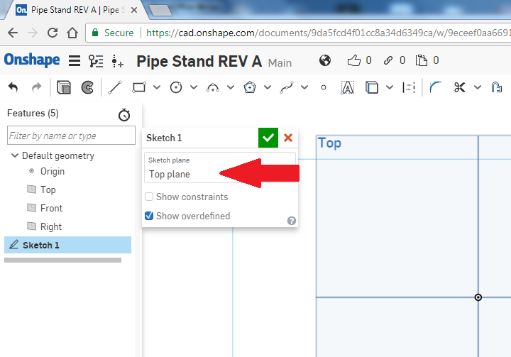
Once we select “Top,” the top-plane selection is confirmed in the Sketch 1 box as on Photo 7.

08_Centerpointcircle
Photo 8
09_Circledrawn
Photo 9
10_Extrudeicon
Photo 10
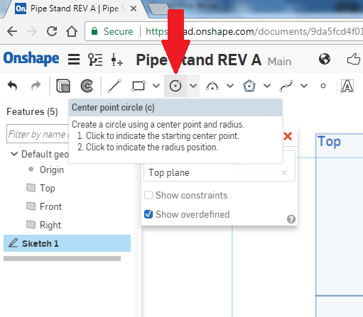
We need to make a circle in the sketch plane to make the outside of the pipe stand. Left-click on the circle icon (Photo 8). (Note: you will notice in the picture below that, if you hold your mouse on the icon for a couple of seconds, a help dialog will appear.)

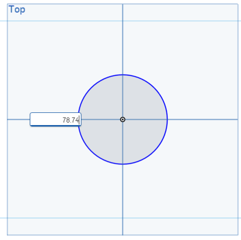
Here I have drawn the circle by first left-clicking on the center of the sketch plane then moving my mouse out to make the circle (Photo 9). Once the circle has been completed I type in 78.74 to represent that I want a circle whose diameter is 78.74mm. I got this from the dimensional drawing made for the base.

Now we will use the “Extrude” command to make a long rod (Photo 10). This has the effect of “pulling” the circle to make a three-dimensional rod. The red arrow shows the icon and the help dialog comes up if you hold the mouse on the icon for a couple of seconds.

11_Extrudedialogbox
Photo 11
12_Extrudedialogboxdataentry
Photo 12
13_Extrudedrod
Photo 13
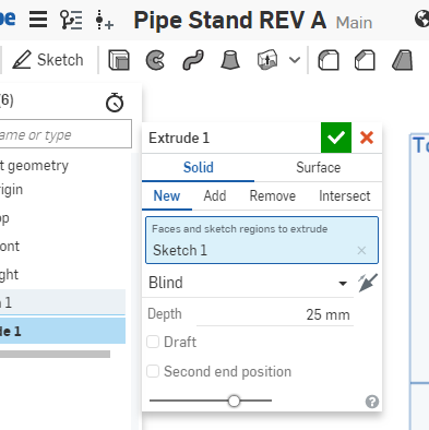
Right-click on the extrude icon and the extrude dialog box appears as shown in Photo 11. By reading through the dialog box, you can tell what is going to happen. This is a new extrusion; the faces and sketch regions to extrude is Sketch 1; it is a blind extrusion; and the depth right now is set to 25mm.

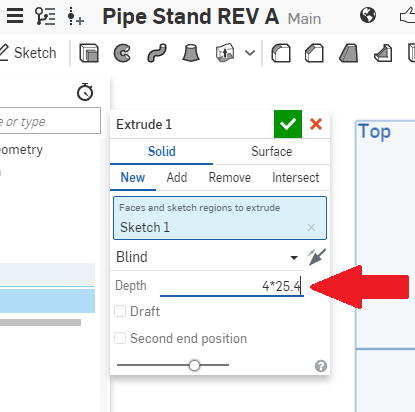
We need to change the depth of the extrusion.  Since I want it to be 4” in length I enter 4 X 25.4. The program will do the math for me (Photo 12).

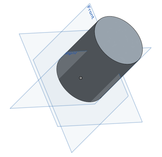
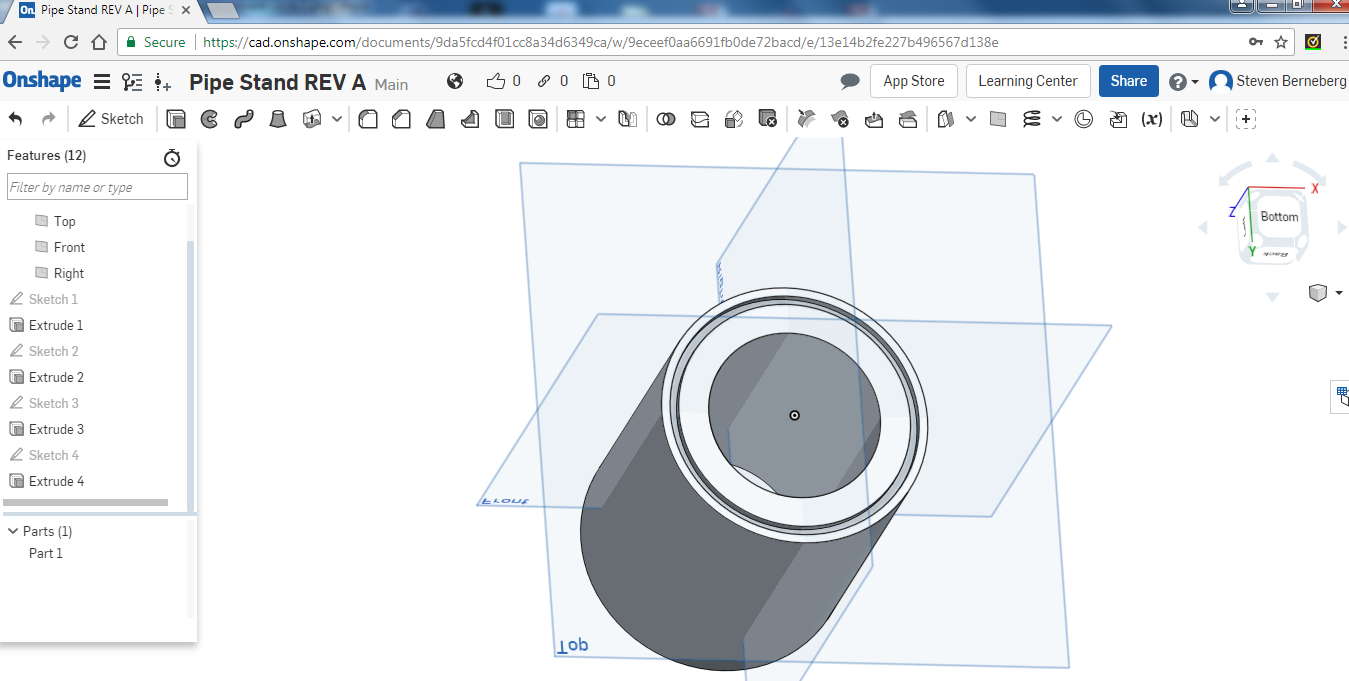
Here is what it now looks like (Photo 13).

14_Innercirclesketch
Photo 14
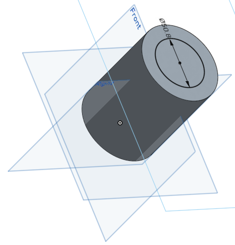
At this point I need a hole in the center of the rod through which to pass the water pipe when all is done. I am going to make it the same size as the one in the Base – 50.8mm. Left-click on the Sketch icon again, then left-click on the very top of the rod; it should now be highlighted and, in the sketch dialog box, it should say “Face of extrude 1.”  This is where we are going to draw another circle. Left-click on the circle icon again, find the center of the selected area, and draw another circle.  Then enter 50.8. It should look like Photo 14.
15_Extrudecentercircle
Photo 15
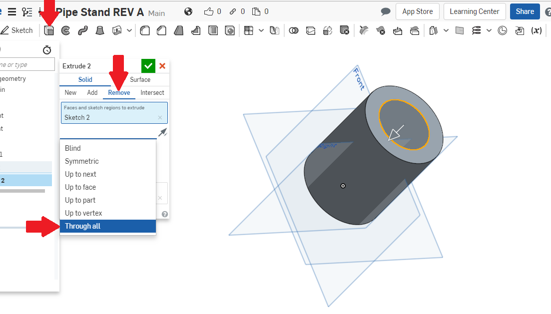
Now we will use the extrude icon again, but this time we have a couple of extra choices to make. The very top red arrow on the picture below again shows the extrude icon.  When the extrude dialog box comes up, choose “Remove,” as shown by the second red arrow near the middle of the picture. Next, we have a pull-down menu that we use to remove material: choose “Through all.”  When done, left-click on the check mark in the green box and it should take away the material as requested. If you scroll around, you will see the hole in the rod, now a cylinder (Photo 15).
16_Extrudealignmentcircle
Photo 16
We have two more things to do: create the alignment circle as we did in the base and create a circular area for the base-alignment circle to fit in.

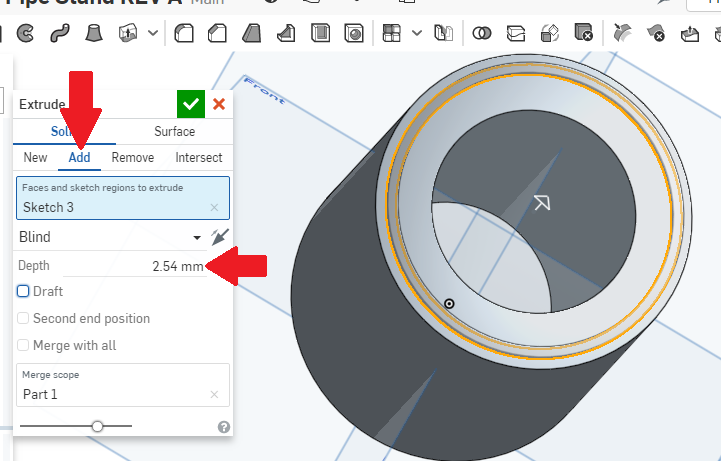
The raised, circular pattern for the alignment circle is next. We will again make a sketch and create two circles, one 68.58mm and the other 73.66mm. Again extrude those to create the alignment circle as shown in Photo 16. Remember that we are going to add material and the depth is going to be 2.54mm.

17_Rotation
Photo 17
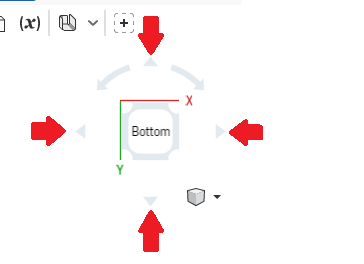
Next, an alignment circle needs to be cut out of the bottom of the pipe stand to match the top of the base. Use the same dimensions as the top alignment circle.  First, rotate the object by using the rotation icons in the upper right-hand corner of the drawing. The red arrows show the rotation direction in Photo 17.  Try it — you cannot do anything that you can’t get out of.
18_Negativeextrudealignmentcircle
Photo 18
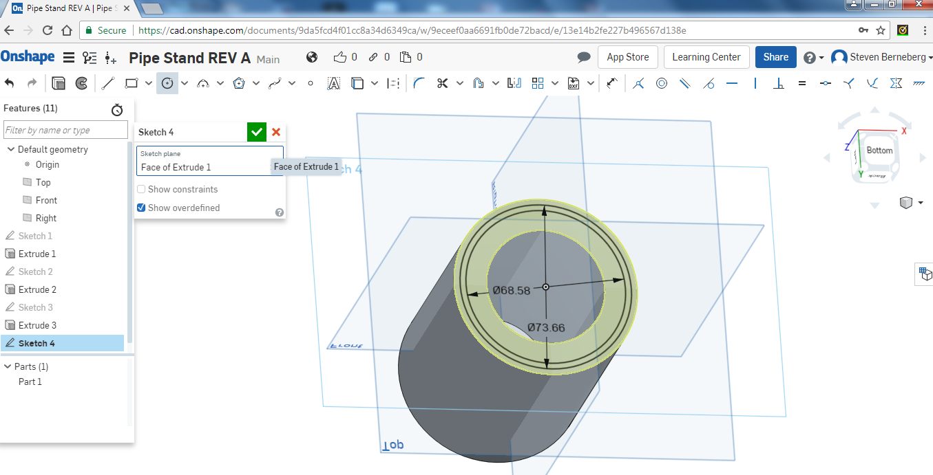
I drew the circles as before to make the alignment-circle cut. This should match the alignment circles that we made earlier for the extrusion (Photo 18).
19_PartComplete
Photo 19
I then removed the area between the two circles by first selecting the circles, then choosing the “Extrude” icon, but under that choose “Remove.” That will remove the area instead of adding to it. Set the depth to 2.54mm and click the green arrow. The part is now complete (Photo 19).
20_Berneberg
Photo 20
Exporting an STL file
To create the stl file, I am going to just repeat the process from last time.

Now that we have the part, we want to export an *.stl file so the printer can print it. At the bottom of the window you will see a tab called “Part Studio 1.” Right-click on the tab and you should get the following:

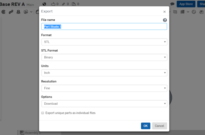
Left-click on “Export” in the pull-down list and the following should appear as shown in Photo 20.

I typed in “Pipe Stand” as the file name. Make sure all other pull-down boxes are as shown. When you left-click on “OK” the .stl file should download to your download folder. You can retrieve it from there.

21_MCPipeStand
Photo 21
Load into 3D printer
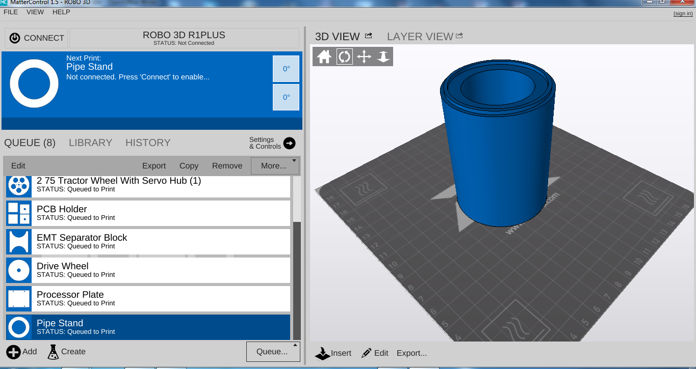
Following the instructions for your 3D printer, load the file that has been created. In my case that is “Pipe Stand.stl.” As you can see from the screen shot of my printer-control software (Photo 21), it takes up just about the whole build plate. It is a large part; probably the largest part that I have printed with the machine.
22_Pipestand
Photo 22
Print conditions
I will be keeping the lab again at a constant 80°F, with the humidity between 10 and 40%. This is very important because you are going to spend a lot of time and some money printing just the base.  It would be good to get it on the first try. I will be using white ABS, 1.75mm from MatterHackers.

Print
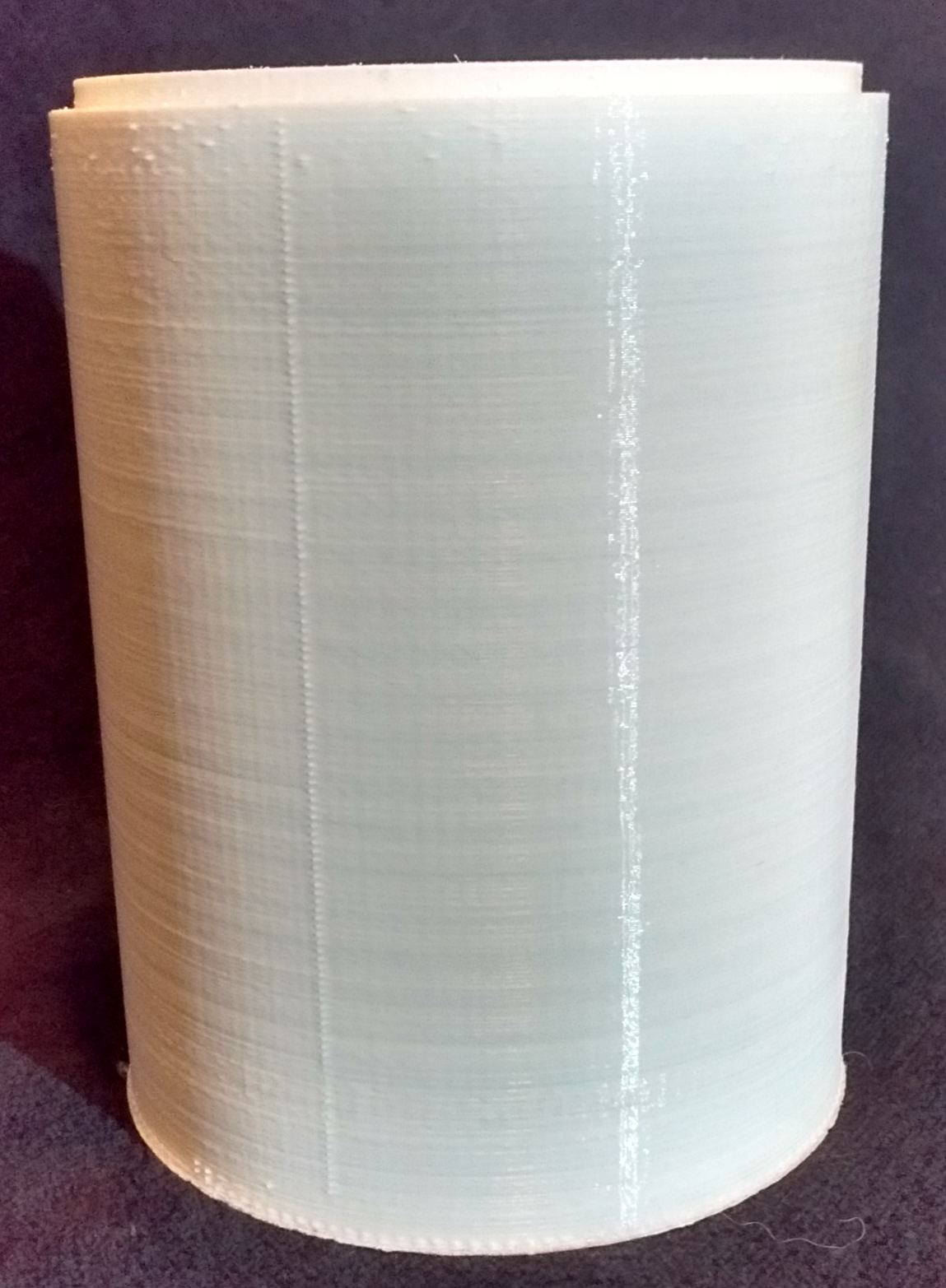
The print of the pipe stand is not as large as the base.  It took about six hours to print and I experienced no warping or cracking.  The finished product is seen in Photo 22.

An acetone vapor bath is next to make sure everything is bound together.

I will make four of these parts to achieve the proper proportion.

Next time we will make the top of the water tower which will take some extra work on our part to include the sprinkler in the top of the water tower.

You must login to submit a comment