How To Projects High-tech modeling for garden railroaders

High-tech modeling for garden railroaders

By Steve Berneberg | August 25, 2017

| Last updated on November 3, 2020

Part 10: Finish the railroad signal project, including making the electronics box and solar panel frames

Email Newsletter

Get the newest photos, videos, stories, and more from Trains.com brands. Sign-up for email today!

On prototype signals there is usually a utility box to hold the signal interfaces and power.  The latest thing is to include solar panels to minimize the infrastructure that must be installed to support the signals.  I am going to include the solar panels because I am getting tired of ripping up my wiring when I go out to weed.

Note: Links to downloadable files are at the end of the article.

Solidworks program
I again will be using Solidworks as the CAD program but you can use any CAD program to build yours to your specifications.

01_PaintedSignalSupportPole
Photo 1
Finishing the signal and support pole

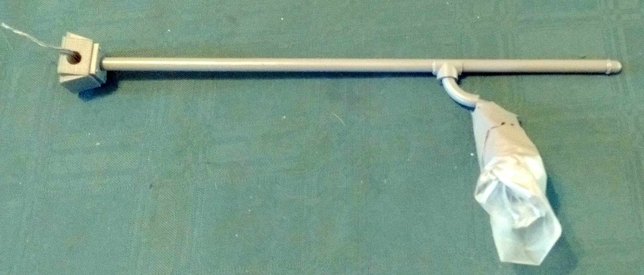
The support pole has been painted a shade of gray and the signal itself has been masked off to prevent overspray (photo 1).  (Note:  It really is gray, not the color that came out of my camera!)

Everything on the signal pole is now ready to put together.

03_18650cell
Photo 2
Solar-cell frame

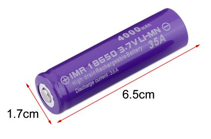
This project, like many of mine, is going to use a single, type 18650, Li-ion cell for power (photo 2).  This cell will supply 3.7V at between 1500 to 3500mAH of current.  (The exception is LiFePO4 at 3.2V.)  The cells are fairly inexpensive due to their extensive use in commercial products, such as the Tesla Model S, autonomous robots, and LED flashlights.  You can get two 18650 cells and a charger for about $7.00 from Walmart.

04_SolarCells
Photo 3
A nice thing about the 18650 cell is that you can charge it directly from a 5V, low-current solar cell. The solar cells for this project came from eBay. 100mA max charge current will not cause a significant rise in cell anode temperature, which is the leading cause of Li-ion cells catching fire. I am also going to put the cell in the equipment box, which will be slightly buried under the soil to insulate the battery from high ambient temperatures (photo 3). The solar cells will also shade the equipment box from direct sunlight. (It gets hot here in Southern California.)
05_FrameandCover
Photo 4
06_framedrawing
Photo 5
The solar cells were supposed to be 100mm x 50mm x 3mm. The first thing I did was to make a hand drawing of all the parts that must go into the frame. I will cover the solar cell with 3mm-thick glass to hermetically seal and protect the solar cell. The frame will be in two parts: the frame body (frame.stl) and the frame cover (frame top.stl).  (Photos 4 and 5)

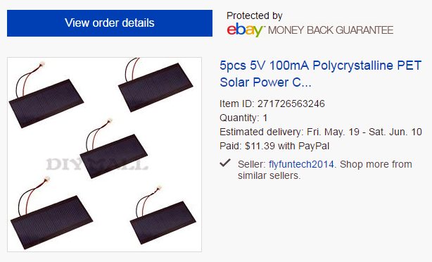
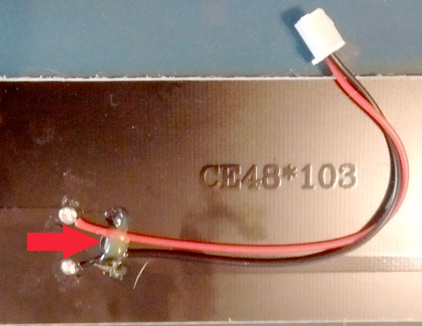
(Post note:  Now that the solar cells have arrived; they do not measure 100mm x 50mm.  They are 103.2mm x 47.9mm, so I have to lengthen the extruded cut to accommodate the extra 4mm. They are also not 3mm thick in total. The wiring needs to be accommodated as well, so I will include another extruded cut and a hole for the wiring.)

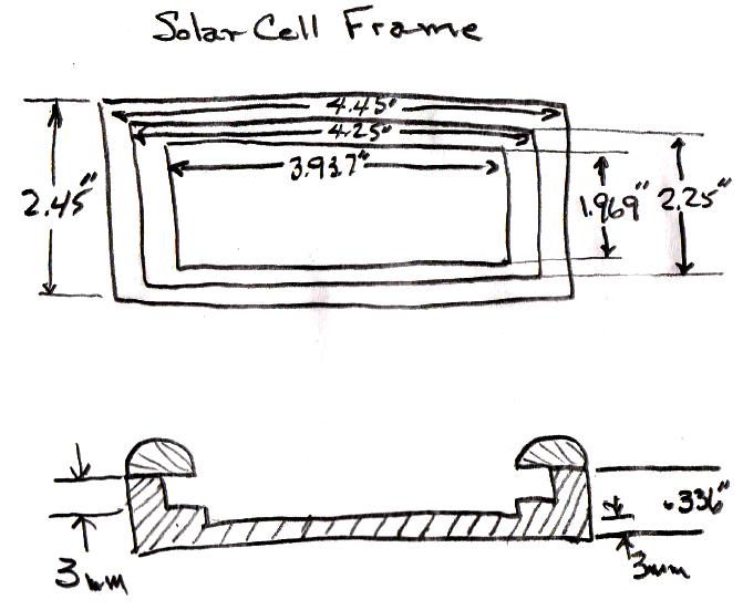
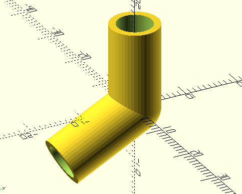
The solar panel will be at an angle for optimum, fixed, collection. For my location the angle needs to be 27.5°. A coupler will be needed to attain that angle and, since I will use the same brake line as the support for the solar panel that I did for the signal pole, the coupler needs to fit over the brake line.  One end of the coupler will be mounted directly to the solar panel frame.

07openSCADCoupler
Photo 6
Sometimes you have to use a different tool to design a part.  This was the case with the angled coupler (photo 6).  It can be done with SolidWorks CAD but I found it to be easier and much faster with openSCAD.  I have talked about openSCAD before; it is my second choice for a CAD tool.  After a couple of minutes, the part was done.
08_Solarpanelparts
Photo 7
09_SolarPanelWires
Photo 8
Solar panel

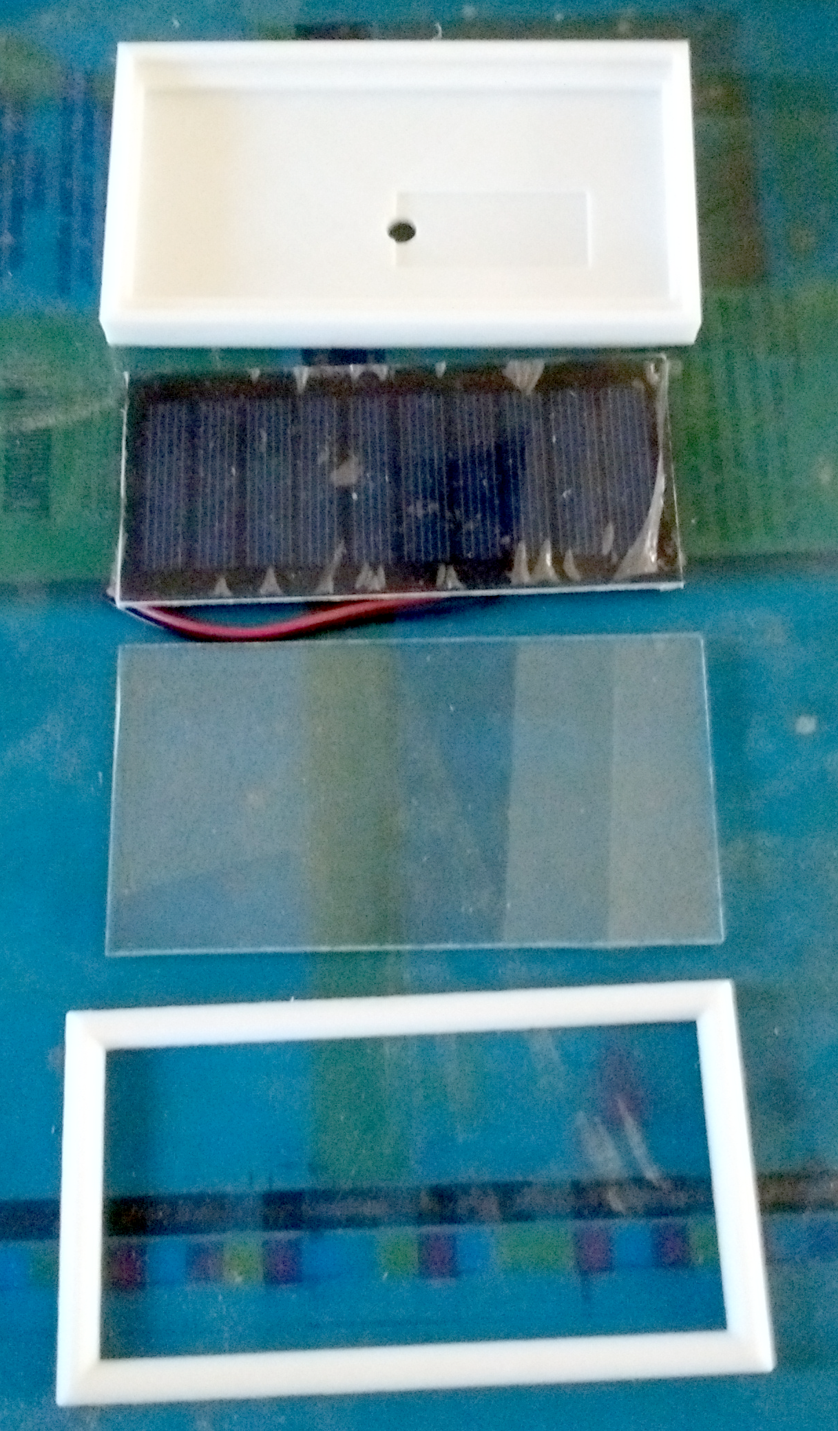
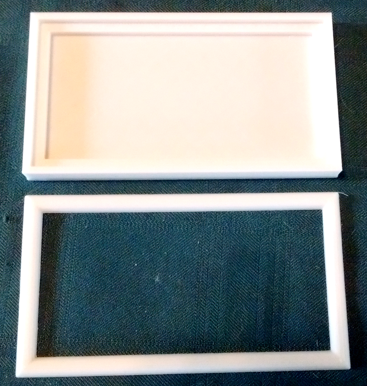
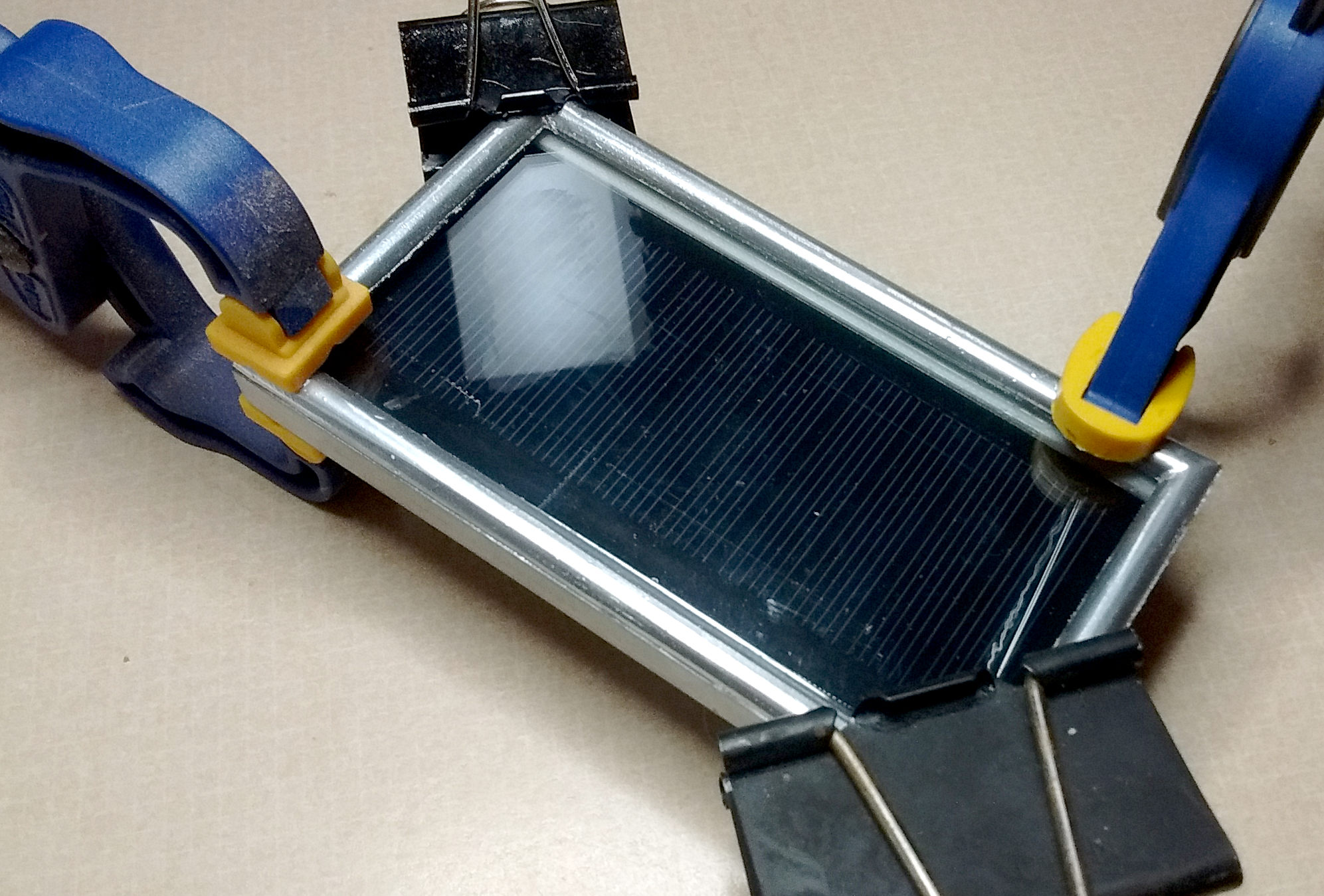
Here are the components for my solar panel (photo 7).  As shown, there are four parts: the frame itself (frame.stl), the solar panel, glass, and the frame cover (frame top.stl).  The ABS parts will be painted first, then I will put everything together.

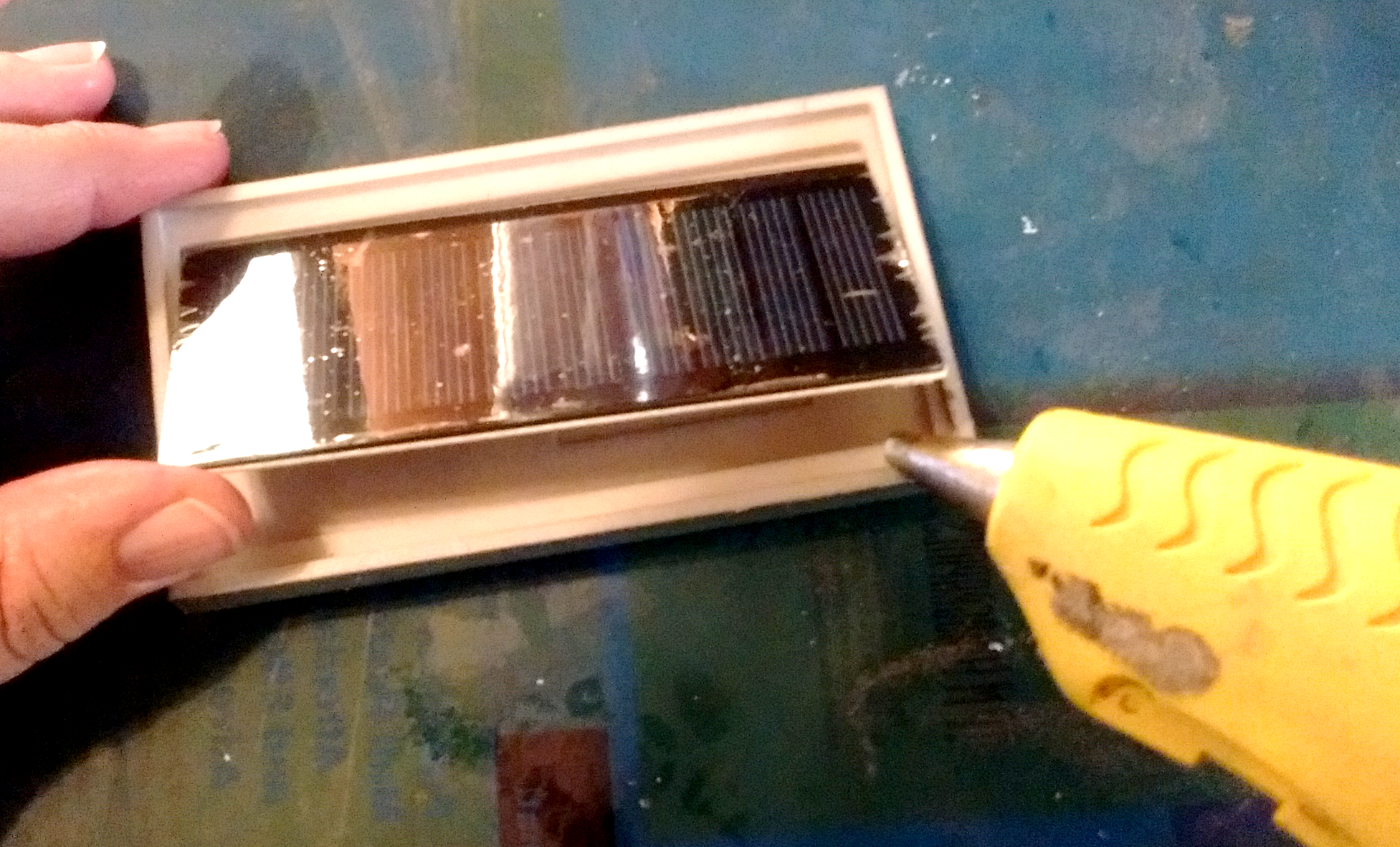
However, I first need to cut off the supplied connector on the solar panel and glue down the wires to provide some mechanical relief.  I used a hot glue gun, which works fine (photo 8).

Once the wires have been secured, the connector cut off, and the frame painted, it’s time to start putting everything together.

10_GlueSolarPanel
Photo 9
First, make sure the solar panel fits inside the frame (do this before you paint!).  It might require some scraping to get it to fit.  I did this with the edge of a utility knife to form a sort of scraper.  Then just gently lift the panel off the frame and apply two dots of hot glue (photo 9). Hot glue will give the panel the ability to expand and contract as the temperature changes.

Next, the glass goes over the top of the solar cell inside the frame.  I used GE Preminum Silicone Glue along the edges of the frame, then placed the glass inside. Try to make sure the glass is sealed against the environment.

11_Panelframeclamped
Photo 10
12_SolarPanel
Photo 11
Once that’s dry, the frame goes on the top.  Again I used the silicone glue, clamping it securely (photo 10).

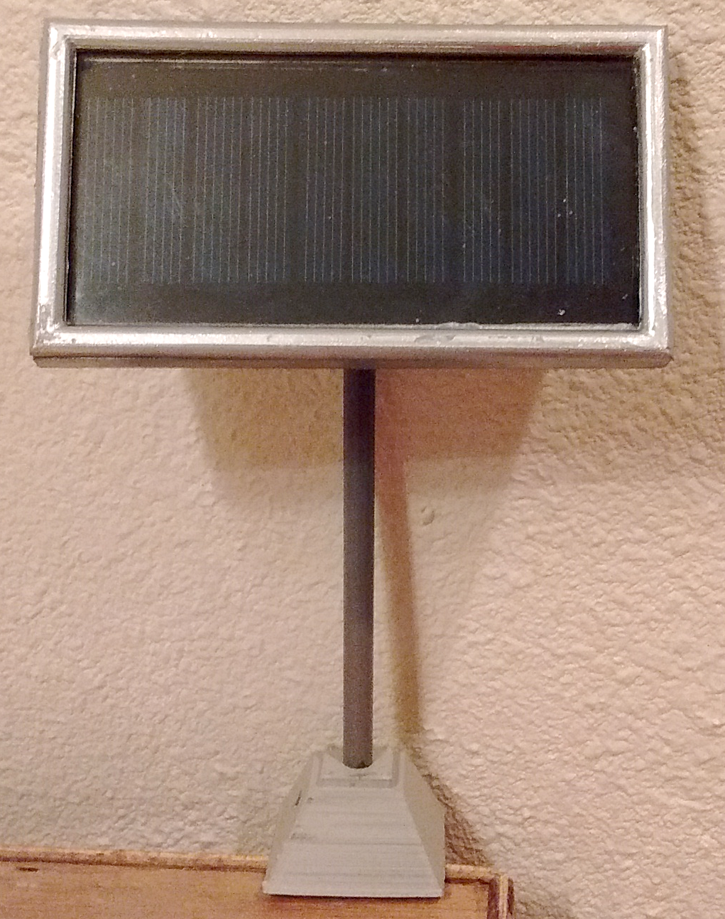
With the support pole and the angled joiner that was printed earlier, the solar panel is now complete and ready to hook up the electronics and plant in the ground (photo 11).

Equipment box

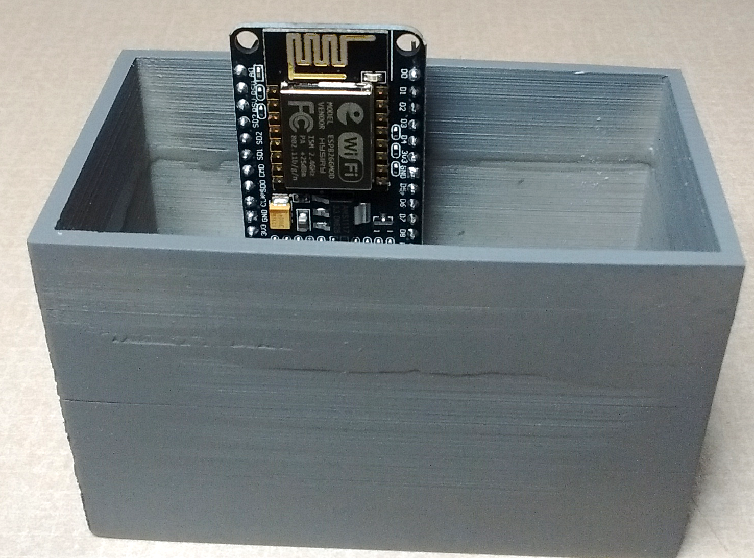
Since the signals are going to be automated, I need an equipment box to hold the battery, constant-current sources, and the WiFi.  First, there are several things to consider:
1. Keep the battery below ground level.
2. Make the box high enough to make sure the WiFi antenna has a clear view of everything above ground level.
3. Make the box long enough to hold the 18650 battery.  

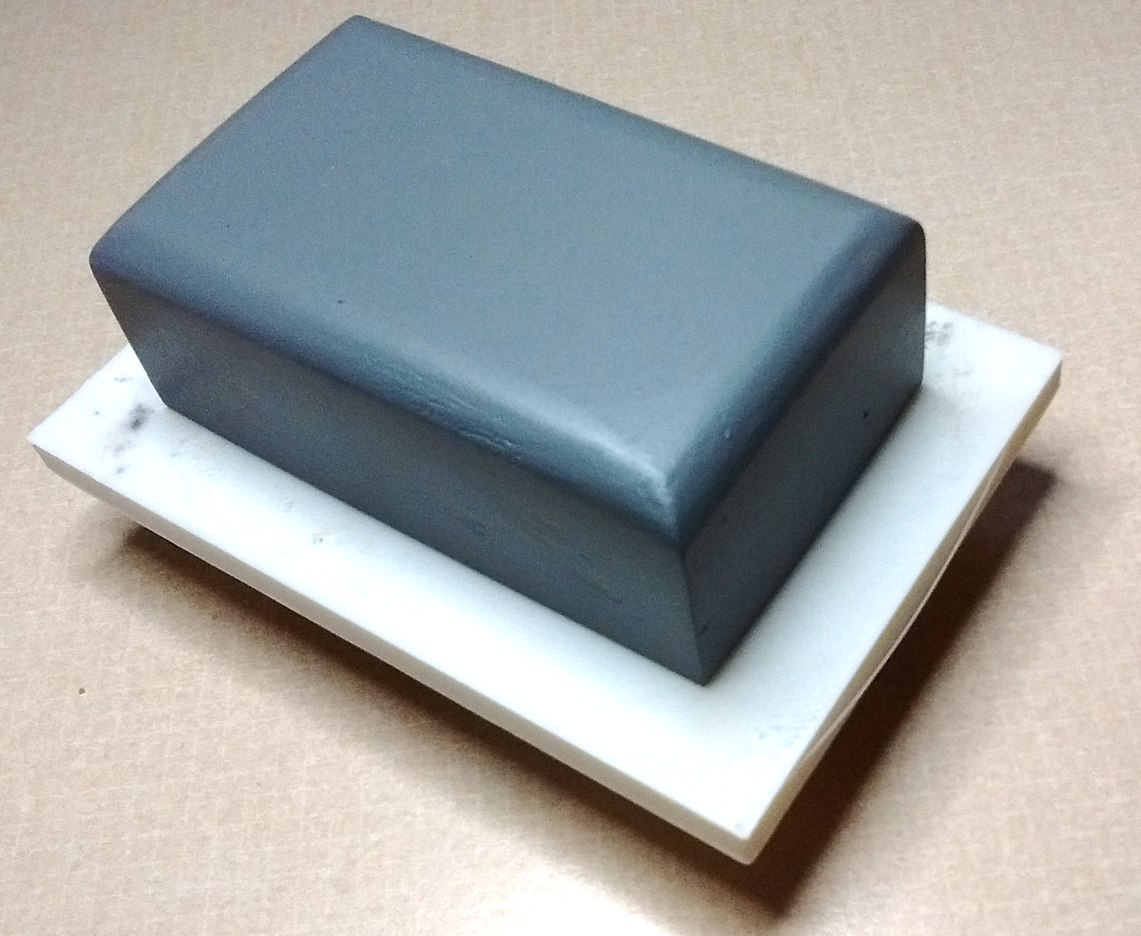
Since it needs to look like an equipment box, I will need a concrete pad like those that equipment boxes usually sit on.  (Note: you can hide the electronics just about anywhere — an old building, a signal hut, or anything large enough to accommodate the components.  The solar panel could be fixed to the roof of a nearby building but, since I don’t want to keep tearing up wiring while I am weeding, I chose the equipment box to keep everything within a short distance of the signal.)

13_Crackedenclosure
Photo 12
14_Brokenequipmentvault
Photo 13
There are three, 3D printed items here:  the equipment enclosure, which is the top (File: Equipment Enclosure.stl); the concrete base, on which the equipment enclosure will sit (File: Equipment Enclosure Base.stl); and the container that holds all the electronics (File: Equipment Enclosure Basement.stl).

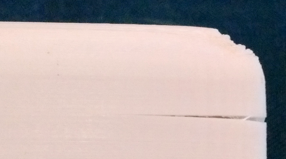
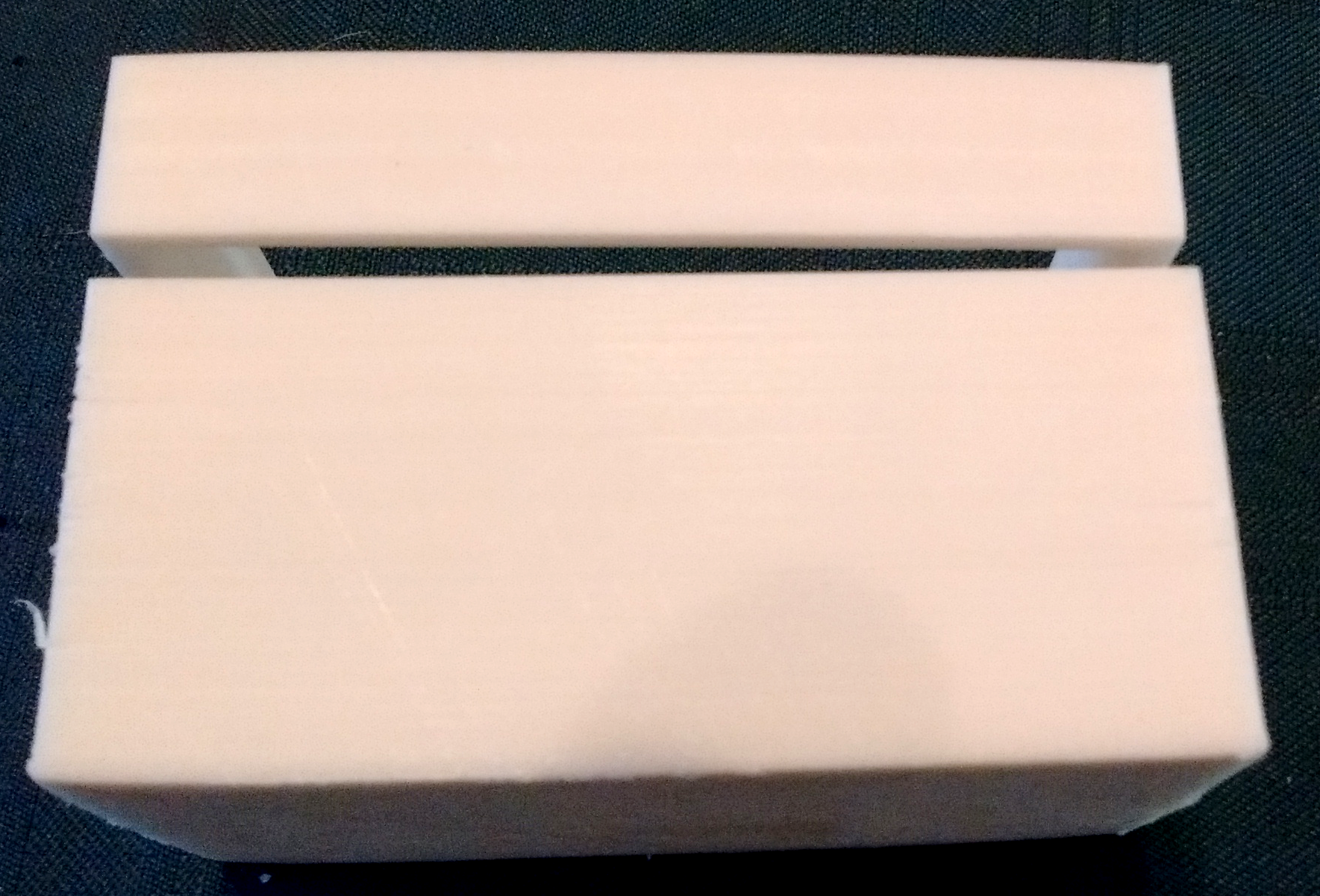
As is typical with ABS filament, there was some cracking (photo 12) and the vault completely separated in my hand while cutting off the flashing (photo 13).

I glued the broken vault together using CA cement, with clamps to keep everything as square as possible.  The separated portion was filled with CA glue and sanded smooth

15_WiFi
Photo 14
Now to test fit the WiFi and make sure the antenna and the battery fit the equipment enclosure “basement”.  The picture is not that good but you can see the squiggly lines on top of the circuit board, which is the WiFi antenna (photo 14).
16_EquipmentEnclosure
Photo 15
Since the WiFi and the battery fit in the box that was developed, I put the concrete pad on the basement section of the equipment enclosure; the equipment enclosure fits over the top (photo 15).
The signal is still not complete.  I have yet to build the ladders and safety structure.  I will return to this at a later date, since many of you have built structures with ladders and a safety structure.
You must login to submit a comment