There are many free modeling programs out there. Each has its advantages and disadvantages. If you are interested in doing custom models, you should pick one program, learn how it works, and use it exclusively. YouTube is a wonderful resource for tutorials that explain how to effectively use the program. In this article, I’ll quickly cover openSCAD, a free CAD modeling program.
I love to model objects for my railroad. That is because I enjoy the journey as much as I enjoy running the trains. I use a good, free modeling program — openSCAD (www.openSCAD.org). It uses a descriptive language that allows you to create objects, cut into objects, and otherwise manipulate objects. A “descriptive language” means that you describe the object using a special language. I will walk you through downloading the program and writing a description of a window.
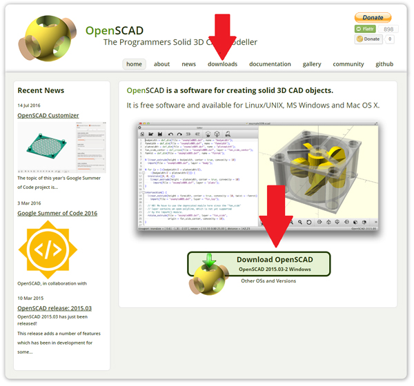
Open your browser and type in the URL www.openSCAD.org. The picture on the right shows two download links (indicated by arrows) that you can use to download the program. The file should be “OpenSCAD-2015.03-2-x86-64.exe” — it is about 14Mb in size. Double click “OpenSCAD-2015.03-2-x86-64.exe” in your browser window or go to the download folder and find it there. This will load the program (photo 1).
If you run another operating system, like Mac OS X, Linux, or UNIX, no worries — they have a program for you. Just pick the right one for you.
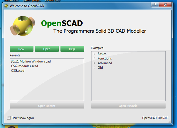
Locate the icon on your desktop or in your programs folder. Execute (open) the program by double clicking on the icon. You will get a welcoming screen such as the picture to the right (photo 2).
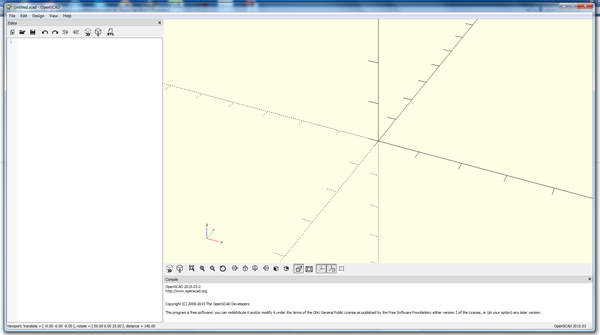
A good place to start is with the examples. They will show you some of the basics as well as some of the finer points of the program.
One important thing to remember is that openSCAD does not use millimeters, inches, or anything else. They have their own units that are dimensionless. When the .stl file is created and exported to the 3D printer software, the units will be defined with this software.
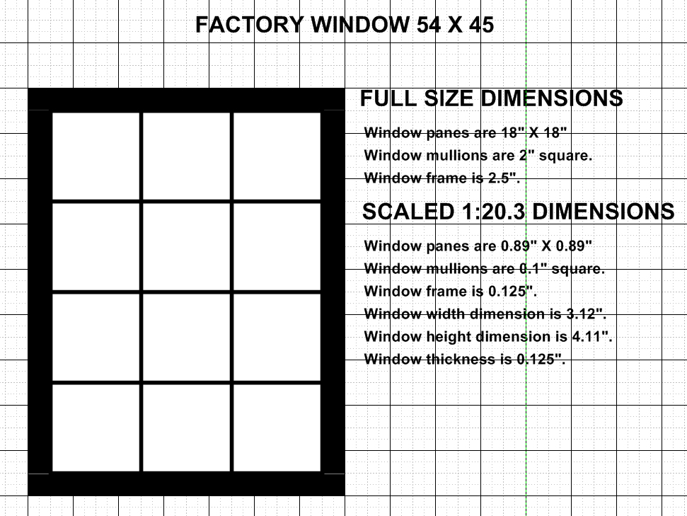
I am building a factory building, so I need some windows. As usual, I will make a rough-draft drawing with both full-scale and the scaled dimensions (photo 4). According to the notes, the rough opening for this window, in scale, is 3.12” in width and 4.11” in height. The depth of the window is going to be 0.125”.
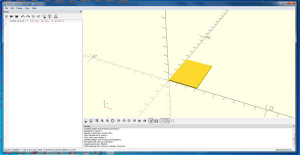
The very first thing to do is to enter the window’s outside dimension. From there we will add and subtract to form the window.
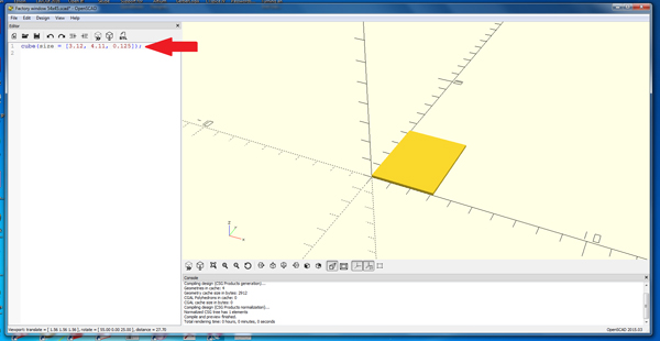
So enter into the editor window the syntax: cube(size = [x, y, z]); For our model, it will come out to cube(size = [3.12, 4.11, 0.125]); Once you do this, you will notice that there is nothing in the graphics window. Not to worry — you have to compile the instructions. Press F5 and the body should appear( photo 5). The red arrow (right) shows the instruction in the editor window (photo 6).
Now we have to cut out the area for the windows. To do this, we will cut out a large area because our mullions are of different thickness than the window frame. We will add the mullions later. We are going to create another cube, then cut this cube out of the cube we just made, subtracting the new cube from the one we have. According to our notes, the area to be cut out is the overall width, subtracting the two outer frames of the window: 3.12 – 0.125 – 0.125 = 2.87. The height would be 4.11 – 0.125 – 0.125 = 3.86. Now we will add another cube: cube(size = [2.87, 3.86, 0.125]); If we press F5 we see that nothing really happens. That is because we have not told the compiler to subtract one cube from the other. We have actually made two cubes, one inside the other. To do the subtraction of one cube from another we will use the difference() function.
If you cannot read the editor window, this is what has been written:
difference() {
cube(size = [3.12, 4.11, 0.125]);
cube(size = [2.87, 3.86, 0.126]);
}
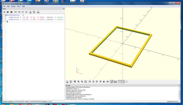
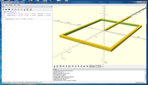
You will see that we have taken one corner out of the cube, which is not exactly what we want. We need a frame that is of equal size around the window. There is an easy fix to this: I am going to change the cube command to add another option that is available. You can center the cube(s) at the origin. Now everything should be symmetrical around the origin (photo 7).
Here is the way the commands are now written:
difference() {
cube(size = [3.12, 4.11, 0.125], center = true);
cube(size = [2.87, 3.86, 0.126], center = true);
}
Now we have to add the mullions. To do this, simply add more cubes with the dimensions of the mullions. To make the vertical mullions, we need a cube that is the length of the cube that we subtracted: 3.86. The other dimensions, according to our notes, are 0.1 x 0.1. Let’s give it a try (photo 8).
This doesn’t look right. I didn’t use the “option center = true” because there are three window panes in this direction, so I cannot have one down the middle. There is another command that we can use: translate([x, y, z]); That will translate (move) the object to the desired location. In addition, we can use mathematical statements in the translate function (or any of the others like cube) to make things easier.
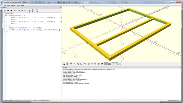
union() {
difference() {
cube(size = [3.12, 4.11, 0.125], center = true);
cube(size = [2.87, 3.86, 0.126], center = true);
}
translate([2.87/6, 0, -0.0125])
cube(size = [0.1, 3.86, 0.1], center = true);
}
You will notice that I have a function union() to start the instructions. This is because we have to tell the compiler that the part(s) we are adding we want these to be part of our original part. Using the union() function ties all the cubes that we have generated into one part.
Next I want to translate the mullion (cube(size = [0.1, 3.86, 0.1], center = true);) to the location that I want. The format for the translate command is: translate([x, y, z]). We know the large area that we cut out to create the “hole” for the windows was 2.87 units and the window itself is centered at the origin. One half of the window equals 2.87/2 units. There are three window panes, so we need to move the mullion 2.87/6 units over. Then, to get it to lay flat on the inside of the window, we need to move it by 0.1 units. We do the same thing for the other mullion, except it needs to go in the negative x direction.
union() {
difference() {
cube(size = [3.12, 4.11, 0.125], center = true);
cube(size = [2.87, 3.86, 0.126], center = true);
}
translate([2.87/6, 0, -0.0125])
cube(size = [0.1, 3.86, 0.1], center = true);
translate([-2.87/6, 0, -0.0125])
cube(size = [0.1, 3.86, 0.1], center = true);
}
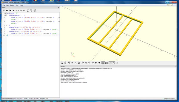
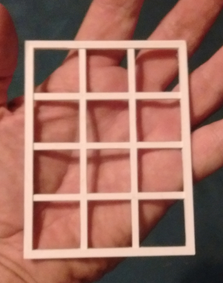
Now we need the cross mullions (photo 10). One is in the very center of the window frame. Therefore I add:
cube(size = [2.87, 0.1, 0.1], center = true);
But I still have to translate it in the Z direction to make it lay flat against the bottom of the frame. Add another translate:
translate([0, 0, -0.0125])
cube(size = [2.87, 0.1, 0.1], center = true);
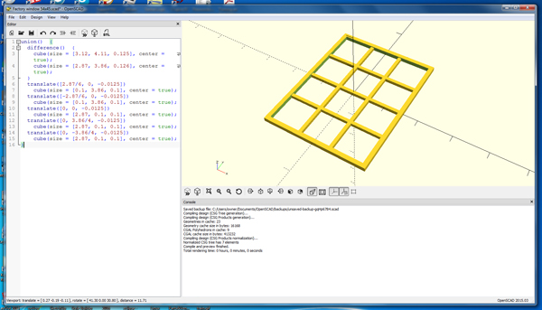
Now add the other two horizontal mullions and translate those to their proper position (photo 11):
translate([0, 3.86/4, -0.0125])
cube(size = [2.87, 0.1, 0.1], center = true);
translate([0, -3.86/4, -0.0125])
cube(size = [2.87, 0.1, 0.1], center = true);
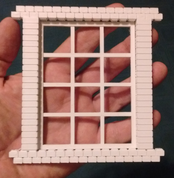
That completes the window frame but, since I wanted this for my brick building, I designed a brick facade in SolidWorks (photo 13). (I only chose SolidWorks because it took me about 15 minutes to do it, vs. about two hours for openSCAD. That’s only because I know SolidWorks and am just a beginner in openSCAD.)
Attached is the openSCAD file — you can manipulate it as needed for your project and experiment with the window. Also attached is the .stl file for the window and the façade, so you can print out what I have created here. You can then send it to your local 3D printing facility, go to www.3Dhubs.com and find a printer near you, or drop me an email and I can print it out for you (sberneberg@yahoo.com).
Next time I’ll be working with another free modeler that many have suggested: Sketchup.