In your empire, it’s good to have choices when building a viaduct over land or water. This story recognizes the uniqueness of each bridging circumstance. Bridge the track from one hill to the next or carry your railway down a long slope. You can link your garden railway to the history of age-old structures. Add curving arches to your yard for a more organic centerpiece. The rules of construction must match the “sense of place.”
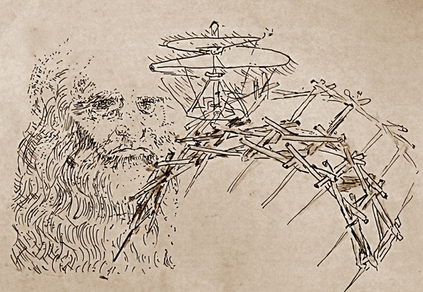
Leonardo da Vinci (1452-1519) had an eye for proportion and a head for math. He also had a hand in creating bridge formulas and a helicopter design hundreds of years before they were “accepted” by modern engineers. His self-supporting, portable arch bridge (photo 2) was used in battles to get soldiers over obstacles like water, then re-kitted and carted to the next fence or stream. This design shows the inherent strength in an arch.
Build a bridge…
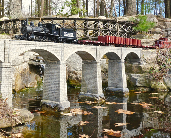
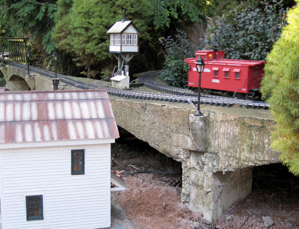
Nothing is more encouraging than seeing others’ success. Stan and Deb Ames’ second attempt (photo 1) is a knockout. Stan and two others tell how they constructed viaducts in Regional reports.
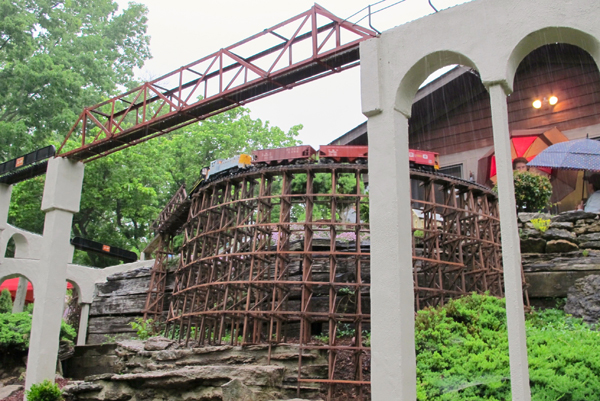
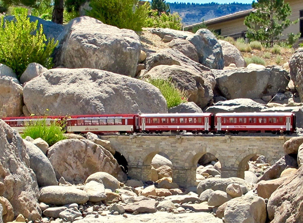
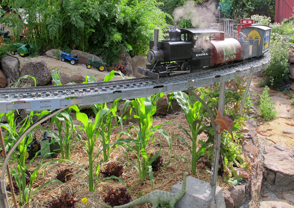
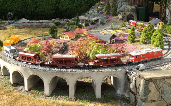
In their steeply sloped Ohio yard, Ray and Charlotte Hughes figured out how to cantilever their railway out over a cliff by installing a series of tall viaducts to keep the track grades reasonably level (photo 3). In the Sierra foothills, Hawley MacLean made two stone viaducts to switchback up a hill crossing a dry creek—no worries during spring washout season (photo 4).
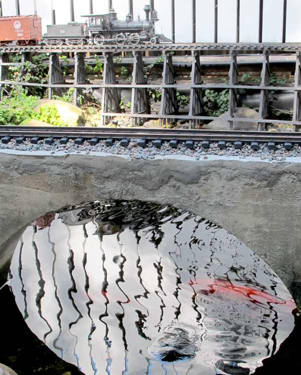
Longevity is a good reason to build with concrete. Like Harry Potter’s train (see sidebar) securely crossing a weathered Scottish viaduct, the Bennetts’ Illinois viaduct lights up with stories (photo 5). The Archers’ Key West Extension in Florida uses concrete in water (photo 6), also called a Roman arch bridge. Concrete colors applied in overlapping stages with rags will age the look.
…and get over it
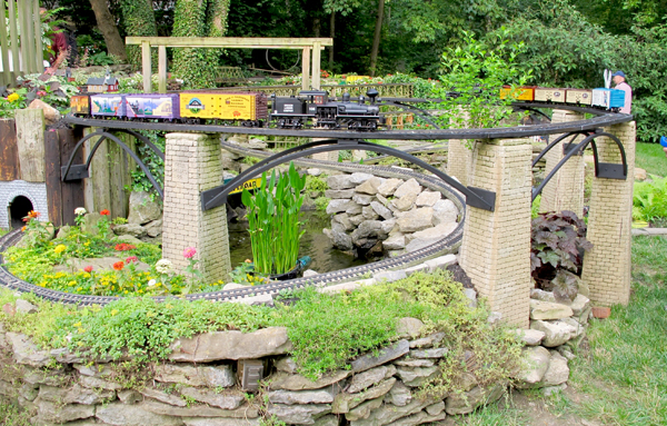
For me, erecting a viaduct in my Aggie has taken time and circumspection. Early mistakes progressed to new directions. I worked with a welder to fasten a steel frame out of Flex-C Trak, galvanized steel posts, and curved rebar or shelf steel (photo 7). This skeleton of a viaduct allowed us to run trains for two years. We will have to wait for the finished look. I’ve already come to terms with the idea that it will be more of an art piece than prototypical, and yet functional all the same.
Garden Railways outdoor-viaduct resources
“The Bourg La Reine,” Aug. 2000 (0-gauge concrete)
“Stone viaducts,” Aug. 2000 (mortar-filled cast resin)
“Aesthetic abutments,” Dec. 2013 (bridgescaping)
“Cement products, part 2,” Feb. 2015 (tile on concrete)
To order, visit our online catalog or call 800-243-4989.
10 prototype viaducts to model
It’s said that cement products will get stronger during the first 100 years, then start to get weaker. Some have been decommissioned about 90 years after their construction.
• Brusio Circular Viaduct, Switzerland: limits rail gradient to 7%
https://tinyurl.com/BrusioViaduct
• Chelfham Viaduct, England: view from the top
https://tinyurl.com/Chelfham
• Glennfinnan Viaduct, Scottish Highlands: Harry Potter’s Hogwarts Express runs over it
https://tinyurl.com/Glennfinnan
• Lewin Kłodzki, Poland: holes between arches
https://tinyurl.com/LewinPoland
• Millau Viaduct (suspension bridge), France: world’s highest bridge
https://tinyurl.com/ViaductFrance
• Ribble Valley Rail, England: several arch bridges and viaducts
https://tinyurl.com/RibbleRail
• Riddings Viaduct, England: nine-arch sandstone viaduct
https://tinyurl.com/RiddingsEngland
• Semmering Railway Viaduct, Austria: like a gallery
https://tinyurl.com/SemAustria
• Tunkhannock Creek Viaduct, Pennsylvania, USA: labeled “Lackawanna RR”
https://tinyurl.com/TCreekPA
• Varda Viaduct, Turkey: Baghdad Railway crosses a gorge
https://tinyurl.com/VardaTurkey
Scale viaduct instruction
• Shuttering (formwork) construction and removal rules
https://tinyurl.com/shutteringGR
• Form making of one arch to be repeated
https://tinyurl.com/FormMaking
• Helix, sloping, and bridging viaducts in garden railroads (one the author built is in here) Go to https://images.google.com and type “garden railway viaduct.”
• Scratchbuilding/kit instruction: step-by-step HO build
https://tinyurl.com/HOViaduct
Regional gardening reports
Zones are USDA Hardiness Zones What made for a successfully built viaduct?
Stan Ames
Chelmsford, Massachusetts, Zone 5
Weatherproof materials
When we built the first expansion of our railroad, we designed a viaduct going over a pond, with a second stone-arch bridge going over the stream that feeds the pond. We chose a viaduct and bridge built by Lone Star Bridge and Abutments for this project, which looked great but, unfortunately, the material slowly disintegrated in New England’s acid rain and harsh winters. Since this was a key railroad feature, we had to find a solution. Mark at Lone Star no longer had the molds, but he gave us permission to make new molds and cast replacements.
The viaduct is made up of three primary castings: the center span/arch, a pier, and a piece that connects the center spans to the pier. The arch bridge required a fourth casting. We were fortunate to find pieces around the country that had been used indoors and were still in good shape. The sections were fixed up, desired improvements made, and silicone molds were constructed.
The pier and centerpiece were made using two-piece molds, while the center arch required a three-piece mold. For the arch bridge, we built a single-piece mold to allow us to make this bridge in various widths by casting the mold twice and gluing the pieces together.
The next problem was finding a material that would hold up in New England weather. We eventually found a material made by Quikrete called Non-Shrink Precision Grout, sold by Home Depot. This material looks and acts like concrete but is much finer and very hard. The viaduct has now been outside for nine years and looks like new (“Greening,” photo 1 above). We now use this material to cast all of our concrete and stone structures around the railroad.
Keith Yundt
Victoria, BC, Canada, Zone 6b
Help from a friend
As a big fan of the amazing engineering prowess of Switzerland’s Rhaetian Railway, I really wanted to incorporate the look of its curved, sweeping viaducts with their graceful arches. Fortunately, my late friend Fred Malone had built several viaducts for his own line, and helped me using the excellent system of construction he had worked out.
The first step was to prepare a solid base for the substantial weight of the structure, to prevent settlement. In my case, this meant removing the organic soil layer, compacting the subsoil, then putting down and compacting a layer of crushed 3/4″ roadbase (sharp gravel), a minimum of 3-6″ deep. Next, we took a sheet of plywood and cut out a curved base for the viaduct, to have something to which to screw the side forms at the bottom. This bottom piece became sacrificial and was buried under the ground level. Arches were cut into the two long, side forms to match the final desired look, and the sides were screwed to the curved base.
We cut out intermediate pieces of wood for the inner sides of each arch leg and screwed these to the viaduct sides and bottom already in place, to form the vertical portions of each arch. At this point we pounded in some rebar inside each arch base—about four pieces of 1/2″ bar in each segment. We then used tin sheets to span between these vertical wood segments, forming the curved underside of the arch, as the tin takes on a natural curve when secured at each end. We braced under each curved piece of tin with foam or wood to prevent the weight of the cement from distorting the curves when poured. To create a decorative “lip” at the top of each arch, we placed the tin arch slightly lower than the arch cut in the side forms and added another outer form to each side of the viaduct to contain the pour.
Once everything was formed up we placed some longitudinal rebar, bent to the curve of the whole structure. The internal wood and tin surfaces were coated with old motor oil as a release agent. We made sure to have all of our placing tools at hand prior to mixing the cement: a trowel, something to help push the cement down into all the nooks and crannies, and an electric palm sander to act as a vibrator on the side forms to help remove any air pockets and consolidate the cement during the pour. After a day or so, I carefully removed the forms and tried to keep the concrete damp to help the curing process. I dealt with places where the concrete looked open or showed some surface voids by dry-sacking the viaduct. After dampening the concrete, I took an old jute sandbag and rubbed some dry cement powder over the face of the viaduct, filling in all the voids with the dry mix to leave a nice-looking finish. Once the viaduct had cured (say a month), I drilled in some railing posts, laid and ballasted the track, and was ready to test out my tribute to the RhB!
Richard Wolf
Cincinnati, Ohio, Zone 6-7
Opening up the wall
Our vision was of a massive wooden trestle in the very front of the railroad to be the centerpiece, but we soon realized this large “wall” would obstruct the view and create an obstacle to maintenance. My son developed the solution. Large wooden piers were installed first, then a concrete façade was designed and applied.
We constructed a pattern for the piers from 1″-thick Styrofoam insulation. We simply drew our design on the insulation. At this point, we could make any design we wished, so we marked the front and back facades with the railroad name. To line up the mortar lines, we drew them side-by-side on each mold. All together we needed three patterns: one for each side, one for the front and back, and one for the cap. The design was then cut into the foam with a stencil cutter. This enlarged the drawn lines and allowed a solution of 50/50 acetone and dishwashing liquid (a retarder) to melt the Styrofoam to give it a more pronounced effect. Then, to stop the reaction, 100% dish soap with a quick water bath cleaned everything up.
A mold was made with silicone molding rubber and cheesecloth (for durability). We mixed mortar dye into white cement for the pier pieces. For the laminated redwood arches, I constructed an adjustable curved pattern to make an arch of whatever length I needed. I laminated 1/8″ x 1″ redwood strips with Tightbond III glue. The original arches were made of cedar and lasted only five years, thus the change.






I for one would love to see your photo. Yes. I’ve seen good arch bridges in styrofoam, retaining walls, etc. Have you tried dragging your photo into this box?
Really enjoyed this article and the inspiring photos with it. I admire the talent and effort it takes for these creations and have often downloaded photos and articles thinking I would one day ‘get er done’! But being a little less ambitious I’ve created a number of buildings, portals and bridges in stand-alone Styrofoam. Though more fragile I don’t want you to discount this material. My viaduct Styrofoam “stone” bridge has been outdoors for about 8 years with minimal deterioration. Most damage to my Styrofoam creations come from my clumsiness! Would love to provide a photo but don’t see an option for that here.