


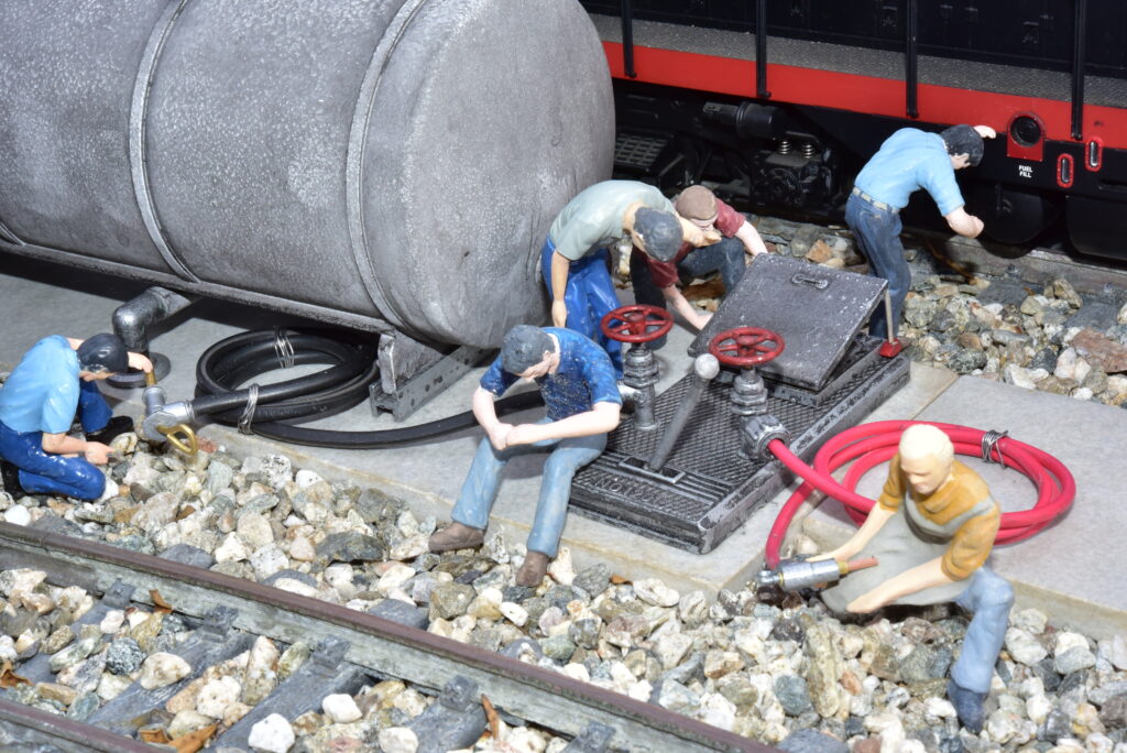
I have a crossing where trains automatically stop and thought it would be nice to add a diesel fueling facility there, but I have a very limited space.
First, I attached a walkway and tank/equipment pad using tile scraps to the main station pad with Plumbers Goop, and brass strips to keep everything in alignment. Because space is limited, I have no doubts the tank WILL get bumped by derailed trains. As such, I glued 5/16” Plastruct “I-beam” saddle locators in place to locate the equipment in the best spot for clearance, but also allow it to easily “break away” if bumped. The down pipe “L-fitting” is a drip system “multi-head” fitting that perfectly fits the hole in the LGB tank. Drip tube and a spacer provide a “downpipe” and “collar” through the “cement.”
Because the tank is at ground level, gravity feed won’t work and a pump system is necessary. With limited space, there was no place for this equipment. I researched prototype diesel fueling facilities and found that many located equipment in underground vaults.
The top of an LGB turnout motor provides the cover for the vault. A Pola roof hatch provides access. I filed the end of the hatch at an angle so it remains open without stressing the glue. A Pola pole, intended as an antenna mast, serves as a selection valve, while a Pola hammer under the lip holds the access cover.
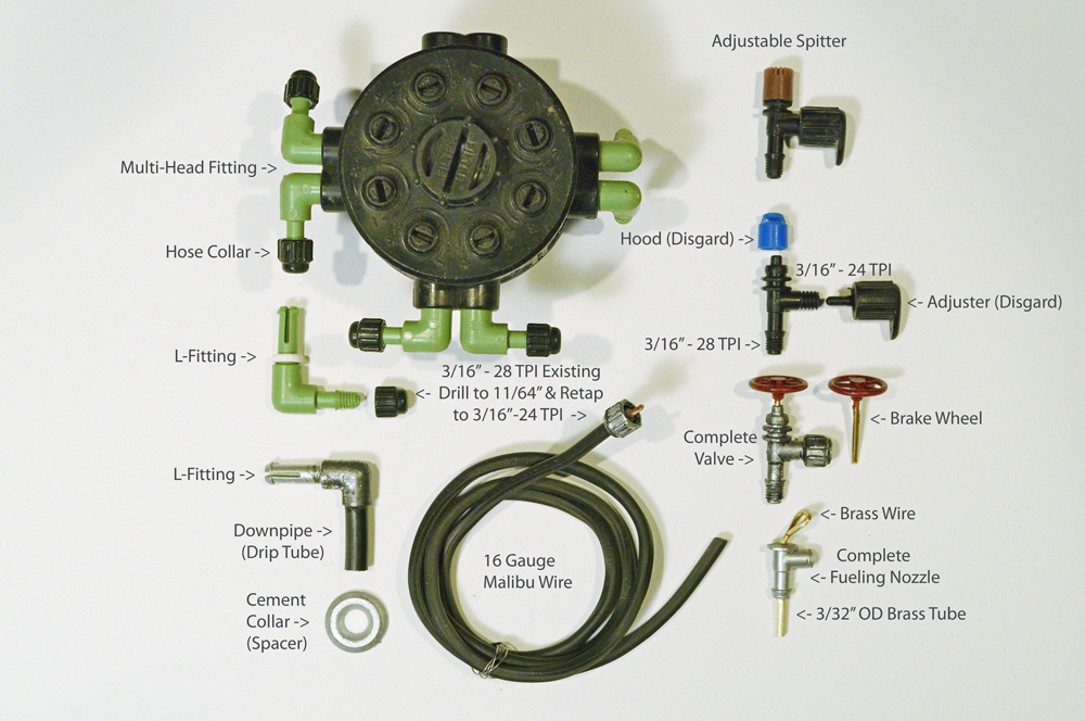
The valves are adjustable “spitters” from a drip system. If you remove the hood, there is a small hole that is ideal for a brake wheel. Non-adjustable spitters can simply have a brake wheel installed to form a subterranean valve.
I enlarged two of the existing countersunk holes in the turnout cover with an 11/64” drill bit threaded with a 3/16”-28 TPI tap for the spitters. Because the cover is raised, it provides space for the spitters’ threads without protruding below the bottom.
The collar that holds the hose to the valve is also from the multi-head fitting, to cover the unused ports. I drilled these through with an 11/64” bit and re-threaded with a 3/16”-24 tap, which is different than the thread on the other fitting. The hoses are 16-gauge wire (black Malibu and red regular) with the end of the Malibu wire stripped to fit into the spitter, while the insulation fits within the collar.
The nozzles were also modified spitters ground down on the disk sander. The larger, high volume nozzle uses a piece of 3/32” OD brass tube, that provides a friction fit in the spitter. A piece of brass wire was bent around a triangular file to form a “stirrup” (to ease handling and start the flow of fuel) and glued into the brass tube.
The smaller nozzle was ground down a bit further. In this case, a piece of 1/16” OD copper tube was placed within the brass tube to form a smaller filler pipe, and the handle/trigger is a cut down cotter pin.
All plastic pieces were painted metallic silver. After drying for a couple days, I added a very diluted coat of Patio Paint Wrought Iron Black and wiped off the detail with a wet finger.


Solder makes great hoses! You can coil, mold it for draping, etc. Paint and weather it, voila!