A quiet revolution changed the toy train industry in the 1930s. Firms aimed to introduce more realistic products. Advances in the die-casting of metals and the compression-molding of plastics shaped that trend.
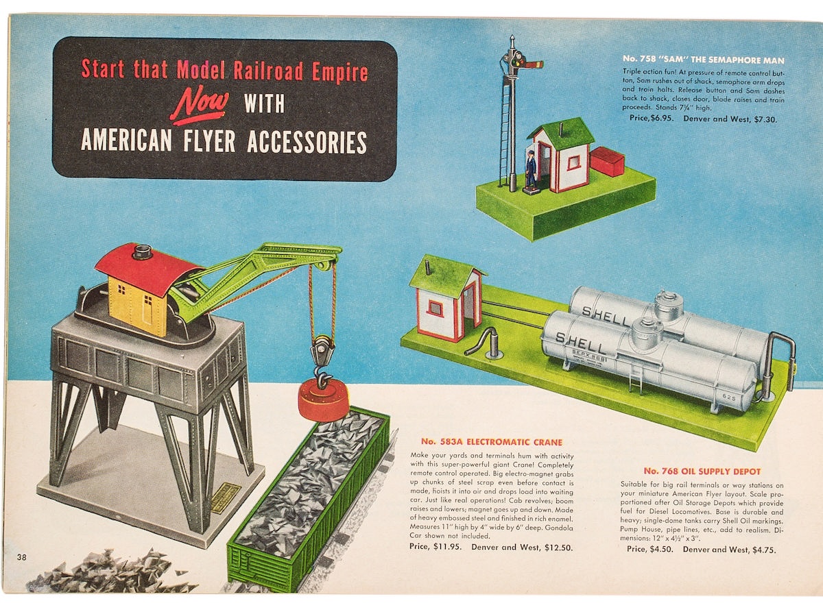
The A.C. Gilbert Co. began to develop scale and semi-scale engines and rolling stock while pushing for greater animation in its accessories. The latter goal led in 1939 to the introduction of the No. 583 electromagnetic crane. That loader thrilled kids before the war and then from 1946 through 1953.
The 583 and its successor, the 583A, hardly changed in appearance over those years. But engineers at Gilbert made minor yet significant modifications to its mechanical workings, including changes for 1949 few collectors have noticed.
Answering a need
The story behind the development of the 583 opened in a curious fashion with the Gilbert Co. championing an HO scale replica of the New York Central class J1 4-6-4 Hudson steam engine and tender. Designers at the firm in New Haven, Conn., elected to install an AC (alternating current) motor in the Hudson.
Unfortunately for Gilbert, every other domestic manufacturer of HO trains used DC (direct current). Worried about losing sales, company leaders responded by having their team of engineers modify the steamer with a DC motor for 1939.
That created a different sort of problem for Gilbert: What to do with all the leftover AC motors? Designers realized they could use the compact parts to solve another dilemma, namely, how to power a reasonably sized accessory. After all, most electric motors were in the late 1930s too big to put on freight loaders and similar models.
The AC motor proved perfect for the electromagnetic crane company leaders wanted to add to their line. Then engineers attached a new transmission to the motor, securing the latter inside the superstructure with three short bolts.
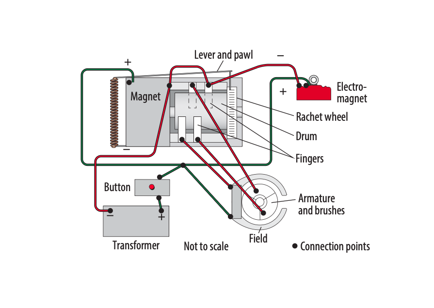
That transmission turned the crane’s cab to the left or right. Designers then had to figure out how to reverse the motor. So, as Fig. 1 shows, they mounted a No. XA8731 locomotive reverse unit to the front wall of the superstructure.
Engineers drilled holes into the face and fastened the prewar reverse unit with bolts inserted through the two horizontal holes. Two vertical holes weren’t used.
Another wide hole provided space for the bolt used to hold the magnet to the reverse assembly. Wiring for the magnet came out of the top at the front edge. A button acted as a switch for the reverse unit. Pressing it sent energy to the magnet.
More details
A key aspect of the crane’s operation involved raising or lowering the magnet. Turning the cab to shorten or lengthen the cord handled that key task. In 1939, when the 583 made its debut, the brass cord was very heavy. It acted as the ground for the magnet because the wire from the latter had only a single strand.
Electrical contact happened at the hook and the magnet eye ring. That arrangement did not work well for completing the electrical circuit for the 583.
Company designers sought to make improvements for 1940. They got rid of the heavy brass cord, substituting a thinner one made of fishing line. The wire to the magnet became two strands encased in a cloth sleeve. Everything must have operated better because Gilbert made its cranes that way after the war until 1953.
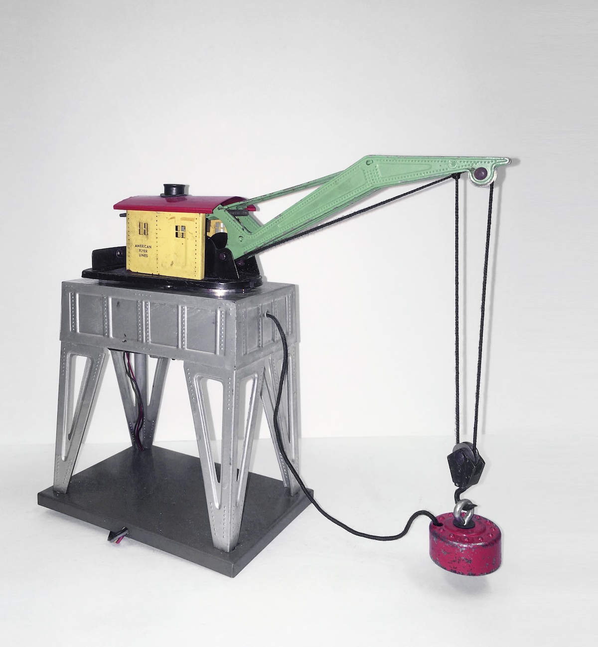
From 1939 through 1942, the 11-inch-high electromagnetic crane had a sheet-metal superstructure (base, legs, deck, and platform) painted dark gray. From 1946 through 1949, the base was painted gray or green, and the legs and deck were gray. An American Flyer decal was affixed to the 4 x 6-inch base.
The sheet-metal cab, or house, always was painted yellow. Further, it usually had American Flyer Lines lettering. The cab, which had a red roof and a black stack, came on a moving deck painted black. The boom was green with a red magnet.
Changes occur in 1949 and ’50
The second volume of Greenberg’s Guide to American Flyer S Gauge does not mention changes made to the 583 between 1946 and ’49. Yet experience repairing and studying electromagnetic cranes helped me discern that models brought out for 1949 had undergone a significant mechanical alteration.
Engineers changed the reverse unit after 1948. They replaced the earlier one with the unit developed for postwar engines (part No. XA10587).
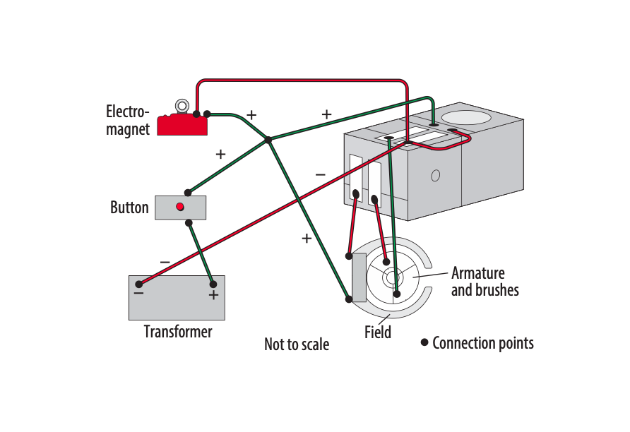
Also, designers attached a platform to the motor as a way of securing the reverse unit (Fig. 2). They bolted the assembly to the superstructure as they had in the past. The wire came out to reach the magnet.
More dramatic changes affected the electromagnetic crane after 1949. In fact, Gilbert thought the accessory merited a new number: 583A.
Cosmetically, the superstructure went from gray to silver. The revolving platform was painted black. The cab and roof did not change. Finally, the smokestack could be painted black or even left unpainted shiny sheet metal.
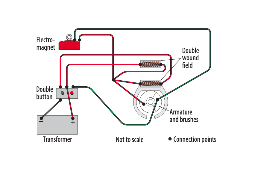
Mechanically, the 583A used a motor with a double-wound field (Fig. 3). Engineers hooked the motor up to a completely new transmission. Gone was any sort of reverse unit. The wire to the magnet came out of the face of the superstructure. Two panhead screws held the assembly together.
A controller with a pair of buttons smoothly moved the 583A crane in a counterclockwise or a clockwise fashion. That was one more way in which the Flyer cranes differed and, as a result, should not be considered interchangeable.

Still popular
Marketing executives at the Gilbert Co. decided to remove the 583A electromagnetic crane from the American Flyer catalog after 1953 and never replaced it with a similar operating accessory. What a shame for S gauge modelers of all ages back then.
The decision strikes me as surprising if only because the electromagnetic crane has proved to be incredibly popular with the youngsters who see the Flyer operating displays I have constructed and put on public display over the past years. They find so much to enjoy and play with on this classic accessory.