Here are a few tips and tricks when working with MTH RealTrax:
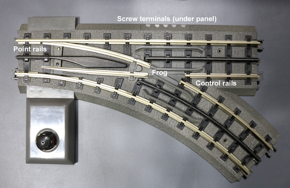
- The two ground rails are not tied together. This is true for other track systems using non-metallic ties, including those from Atlas O and GarGraves. If you add a switch, you need to add a lockon and make sure it’s on the opposite side of the track from the first lockon. This assures ground on both outside rails and prevents loss of ground through the switches. It also enhances the signal using a command system, and it gives a better chance that the ground power will be on all the track sections in case a copper connector was missed during assembly.
- The larger the layout becomes, the more lockons are needed. Alternate the sides as you install them. MTH sells a separate ground track, which connects the two outside rails. If you can’t find an MTH ground track, it’s easy to make. Take any piece of track and solder a wire (under the track) from one copper contact to the other ground rail.
- If you’re having trouble snapping the track together, put a small drop of plastic-compatible oil, such as Labelle no. 108, on the mating plastic connections.
- If you have an area where trains stop, remove the track in question and check that the copper contacts are still spot-welded to the rail. If they are, use a digital multimeter set to read resistance in ohms to check continuity. Disconnect the transformer, and then hold one probe on top of the rail while gently pressing down on the copper contact. It should show continuity. If it doesn’t, the weld has broken and you should replace the track. Or see no. 5.
- Fortunately, a broken weld is easily fixed. Using a 1⁄16-inch bit, drill through the copper contact slightly into the rail where it was spot-welded. Using a soldering iron, fill the hole with solder.
- A “chattering” switch or a switch that throws by itself is usually caused by the non-derailing feature. Underneath are two ground rails that come together to form a V; they throw the points if a train approaches and they’re set in the wrong direction. Once wheels have touched them, they ground and energize the switch rails to throw the points. Sometimes when the track hasn’t been laid straight, it can cause these rails to touch. One way to solve this is to grind a small amount of metal from the end of the rail and insert a piece of plastic as an insulator. Attach the plastic to the rail with super glue, and sand to the same contour as the rail.
- If a train stops after going through a switch, the ground was probably lost. Place another lockon after the switch on the opposite side of the first lockon. Check track continuity before, through, and after the switch.
- If the points fail to close against the stock rail, turn the switch over and remove the bottom plate. You’ll see two small, V-shaped springs with a round piece of plastic between them. Both legs of the spring should be on the same side of the post. If one has jumped over, carefully lift it to the correct side.
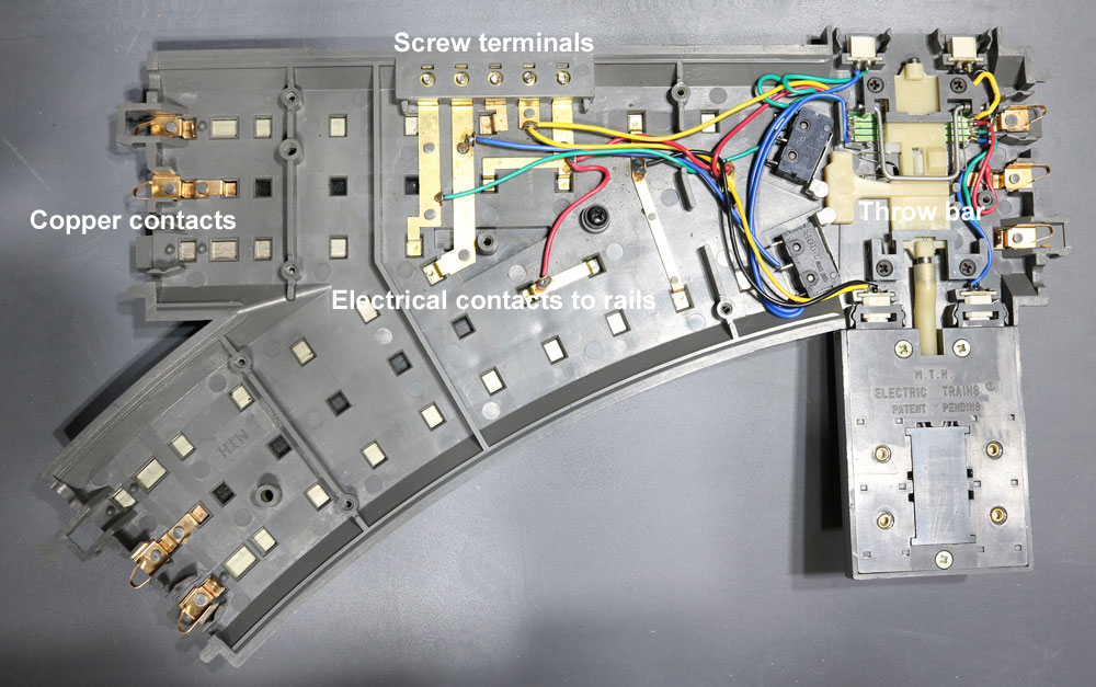
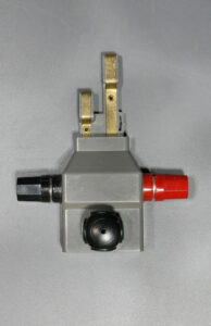
- Switch won’t throw? When using track power, be sure the copper jumper under the first two screw terminals is making contact. If you’re using auxiliary power, remove the jumper. Sometimes it’s just a matter of reseating the switch motor. Watch the small magnets in the throw bars. They’re sensitive to polarity, which can repel instead of grabbing the throw bar if in the wrong direction. Most often it’s a problem with the controller. Take the controller apart and remove the light bulbs. Set your multimeter to ohms, and touch one probe to the black wire and the other to the red one. Move the handle and check for continuity. Then check the green wire and bend the copper contacts as needed.
- You can test switches on a workbench. Using wires with alligator clips, hook them to a power source. Clip the red, or hot, to a center rail. Take the ground, and touch each of the control rails for the non-derailing feature opposite from where the points are set. The switch points should throw to the correct position. Next, touch the ground to each of the two screws where the red and green wires would go from the controller. The switch should throw both ways.