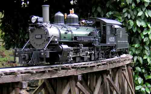
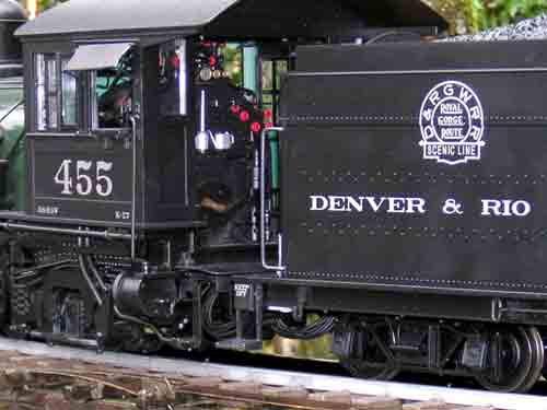
1:20.3 scale, gauge 1, K-27 2-8-2
Bachmann Industries
1400 E. Erie Avenue
Philadelphia PA 19124
Price: $1,400
Web site: www.bachmanntrains.com
Plastic and metal model of D&RGW K-27 2-8-2; illuminated headlight, classification lights, cab light, firebox; DCC and sound ready; knuckle and hook-and-loop couplers provided; review sample, #83097-pre-wreck Nº 455, green boiler; 19V Pittmann motor with flywheel; engineer and fireman included; 18-point power pickup; opening cab doors
Pros: Correct scale/gauge combination; affordable plastic construction; excellent finish; flawless paint; high level of detail; good lighting at low starting voltages; sprung chassis; easy access to the tender shell for adding your choice of control and sound systems (not provided); well-detailed cab
Cons: A little too free-rolling; model is longer (in scale) than prototype; water can drain down the inside of the coal retaining doors in tender; front coupler fouls pilot
First, the measurements: Length, beam to beam, is 34″. I’m going to pause here for a minute. I have, spread out in front of me, the oft-maligned June 1973 Model Railroder drawings of this locomotive. These state a beam-to-beam length of 55’61/2″ which, in 1:20.3, is 32.83″ for Nº 461. I know there are many variations between models but, surprisingly, the March 1973 MR shows Nº 450 with the same as-delivered length, to the half-inch.
Tender measurements from MR are 21’101/2″, which scales to 12.93″. The model is just less than 123/4″. The cab roof vent is about 7″ above the railhead-close to the scale cab-roof height of 7.04″. The model’s cab measure 51/8″ wide, cylinders are at 61/4″, and the top of the stack is just under 73/4″in height.
Back-to back gauge readings on the wheels are as follows: Lead truck, 1.574″; drivers, 1.566-1.572″; trailing truck, 1.556″; and tender trucks, 1.570-1.574″. All are good, within G1MRA tolerances, except the trailing truck.
Tender trucks are similar in appearance to those on Bachmann’s outside-frame
2-8-0. These have operating journal-box lids. Sideframes appear to have the same type mounting as with the 2-8-0, except these are also glued in place. Obvious glue was observed when I inspected the truck undersides. This will make it extremely difficult to remove the wheelsets.
The water hatch opens to reveal a hole dead-center that accesses the rear shell screw. Two more screws are under the coal load, which is removed by pulling up on the coal retaining doors for access. There is no provision for screwing the coal load down in the shell, but the four legs under the load have screw holes. A water channel is provided to divert water from a large rectangular hole in the top of the shell, under the load. Unfortunately, this allows collected water to drain down the inside of the coal retaining doors, precluding the mounting of electronics of your choice directly to the floor. There is just enough room on either side of the water-hatch screw hole to mount on/off and volume controls for those so desiring.
In the tender, visible for the most part through the rectangular opening once the coal load is removed, is the new electronics board. This is designed for some things to plug into. For those who don’t want to use the supplied sockets, solder pads are provided along one side.
This interface board provides three switches for motor on/off, track polarity, and track/other. Consumers should be aware that the only screw terminals provided in this model are marked “batt,” and are really only for controllers plugged into the two parallel control system sockets provided in the electronics board in the tender. For other applications, they are “Throttle Output.” If you use any system for control that does not plug into the sockets, and you connect charged batteries to these terminals and actuate the slide switches, you will have a full-speed launch. When feeding through the “batt” terminals, the polarity switch and motor on/off switch work normally. This can be an issue if your choice of control systems is not protected from reverse battery power. The “batt” terminals are marked “+” and “-” but the inputs to the socket assembly actually change polarity by moving the track polarity switch.
The drivers float. They are attached to .7″-diameter axles. These axles surround smaller-diameter axles and are keyed to them. These smaller axles extend through the frames and have the counterweights mounted on them outside the frames. The eight flanged drivers and their larger axles can move side to side 1/4″, sliding on the smaller, inner axles, to compensate for curvature (the smaller-diameter axles and counterweights do not move laterally). There are fine, relatively soft springs between the wheels and journals on each axle and, while the engine is moving, tend to bring the locomotive to center. This locomotive has over 5/8″ of side play at the pilot beam. If the engine is entering an area of tight clearance (a bridge, for instance) from a curve, it might not have sufficient forward motion to allow the springs to center the drivers under the chassis before it hits something. Just be careful during your first several trips.
All drivers are sprung. The catalog says they are equalized, and they are. . .sort of. The vertical equalizers are in place, as are the moving leaf springs, but the horizontal equalizer bars are not pivoted; rather they are free floating. I don’t have a problem with that. It gives the locomotive movement that’s needed on model track. The equalization movement looks good, but it has to be at eye level for you to really appreciate it.
Contrary to the on-line catalog, which claims a 24V motor for the engine, the motor provided is actually a 19V Pittman, with a 1.7A continuous rating and 6.1 in./oz. of torque. The drive uses a smooth worm, with at least a double-lead. I tore our review sample down far enough to see the main brass axle gear and idler and to discover that you need to align the tabs in the plastic axle seals carefully to get the cover back on the gearbox and still allow the wheels to rotate. These seals keep the grease in, the water out, and the large axles from shorting on the metal gearcase.
The drive is very free rolling. Be careful with long trains and steep grades until you become accustomed to its operating characteristics! There is a brass flywheel on the brush-end of the motor.
This locomotive requires that the tender be plugged into the locomotive to operate. There can be no cradling the locomotive for testing on the bench unless you decide to probe the plugs at the back of the locomotive and apply power there.
Various couplers are provided, including drop couplers for use with existing 1:22.5-scale stock, knuckles with two lengths of shank at the new height, and hook-and-loops. The couplers that come installed are short-shank units. The front coupler, if the jaw is open, has about a 1″ throw, side-to-side. With the jaw closed, the throw is about 3/8″. This is because the pin drops and catches between the center two tubes of the pilot. This can be fixed by removing the coupler and grinding off the pin at an angle until it just clears.
No chains for connecting the cut levers to the coupler pins are provided, nor are the loop pins found on the 1:20.3 freight cars from the same manufacturer.
The engine comes with two figures: the engineer from the 4-6-0 and the fireman-with-shovel from the same series.
Starting voltage forward was 1.2V; reverse 1.0V, both at .2A. Full slip on straight track, at 13.5V, drew 1.7A forward and 1.8A reverse. Full slip on a #1600 curve, running forward, was 2.1A. These reading were taken on old brass track, with shiny plating on the drivers. Drawbar pull was 2.5 pounds.
The headlight appears to have a stock yellow LED. It dims in reverse, which is new. Classification lamps are amber. The lights come on just before the locomotive begins to move. What appears to be the standard Bachmann smoke unit resides under the stack. The cab light almost appears orange, and is subdued.
Behind the smokebox door, which seems to be missing two dogs between the hinges, are three center-off switches. One is smoke; next is cab light; and last is “M.L. and F.F.,” which appears to be Marker Light and Flicker Firebox. Switches moved toward the engineer’s side are for “DCC”, while towards the fireman’s side are for “DC.” These are mounted to a large circuit board behind the smokebox front, which has 14 wires that go to the board in the top of the firebox via plug and socket. In front of the upper firebox board is a fan mounted directly above the brush-end of the motor. There is another board (connected with a plug harness) on the floor of the firebox that seems to be a tie-point for driver electrical pickup, motor, and optical chuff.
This locomotive has optical chuff triggers inside the cylinders, one per cylinder, mounted halfway down the piston throw. There is a tab on each piston rod that breaks the optical beam. This will give the correct number of chuffs per revolution. A single wire feeds the sound system of your choice, but check with the manufacturer for any additional work that may or may not be needed to allow this to function.
There are power pickups on all four driver axles and the trailing-truck axle, giving 18-point pickup. Pickups are via horizontal plungers with rollers at the ends. It might be a good idea to keep the pickup roller pins lubricated.
The cab is well-detailed with a simulated wood floor, opening cab windows, open cab doors, and pivoting wind wings. Cab shades are of some flexible material, roof vent opens, and the firebox flickers through a partially open door.
Cab doors do not open a full 90°; rather about 60°. This bothered me a little, as I like doors to be fully open.
I have photos of a half-dozen or so K-27s. Those that had snowplow-support brackets installed appear to have kept the brackets on the sides of the smokebox, even when the plow was removed. The model has holes in the sides of the smokebox for brackets, but no brackets are supplied. I can fix this by filling the holes and trying to match the color or by making and mounting brackets, but it just makes me wonder why the holes only are there.
All in all, this impressive locomotive is a great addition to Bachmann’s 1:20.3-scale line, and for all hobbyists pursuing 1:20:3 modeling, especially those on a budget.