Part 15: Building the top section of a modern-style water tower
In the past two articles, I’ve been building a modern-style water tower:
The base and then
the pipe stand of the water tower. In this one I will create the water-tank portion of the water tower. Hidden inside will be the sprinkler. This is again created in the
OnShape CAD tool that is available on the cloud to everyone.
Now let’s create the serious end of the water tower, the water tank itself with the hidden sprinkler. Using OnShape, I will be invoking the revolve command, like I used to create the base. However, the sprinkler makes this a little more intricate.
Water tank
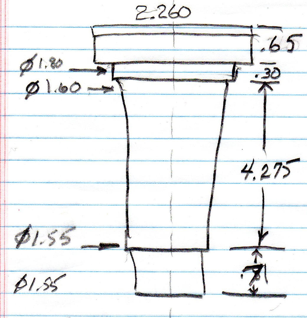
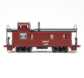
Here is the sketch that I made of the Rainbird model 1804-LN sprinkler head (photo 1). In the drawing I am going to add 0.10” to the diameter to make sure it fits.
Also shown is the sectional view of the water tank. Measurements are all in millimeters.
Start the part
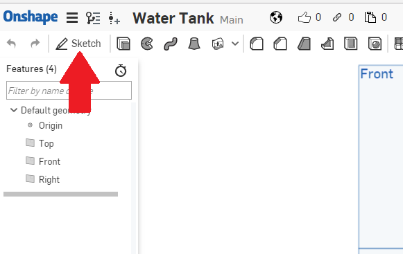
For those of you who might have forgotten, the first thing we want to do is create a sketch. Do that by left clicking on the “Sketch” icon, as shown by the red arrow (photo 2).
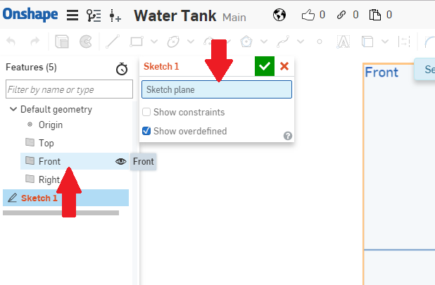
Once you create a sketch, the program will ask you which plane you want to use. As shown by the lower red arrow, left click on “Front” and the Front plane will appear in the Sketch 1 window as shown by the upper red arrow (photo 3).
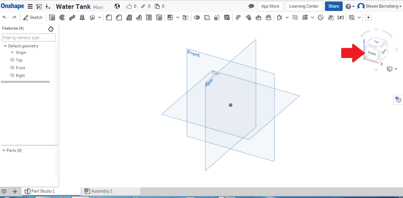
As before, the first thing we should do is align a plane. This way we will work on only one plane for the time being. As shown by the red arrow (photo 4), if you left click on the “Front” face it will align the front plane for sketching.
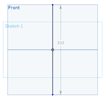
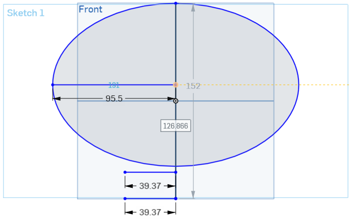
Next, I am going to create a centerline that is as tall as the part I intend to make (photo 5). The line is 152mm long.
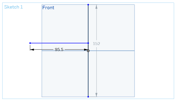
Next, I am creating a construction line of 95.5mm that will define the width of the water tank. I put it just a little above the mid-point of the centerline just to make some room for the coupler on the bottom of the water tank (photo 6).
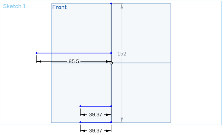
I have created two lines. The first is the bottom of the water tank. Next, I added another line, the same width. This is where the water tank is going to make the transition from the round tank to the coupler (photo 7).
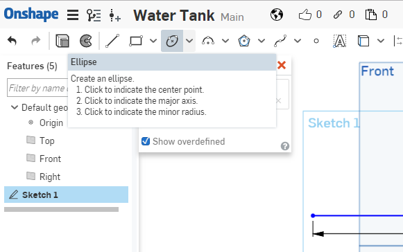
I am going to create an ellipse to make the body of the water tank. If you hover over the ellipse icon, it shows you how to use the command (photo 8).
I have created an ellipse to make the main body of the water tank. I will now cut some of those lines, as I do not want the right-hand side when I eventually revolve the sketch (photo 9).
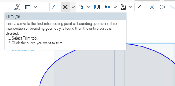
The icon with the scissor allows us to trim off the lines that we do not want. I will use this command to cut away the lines on the right (photo 10).
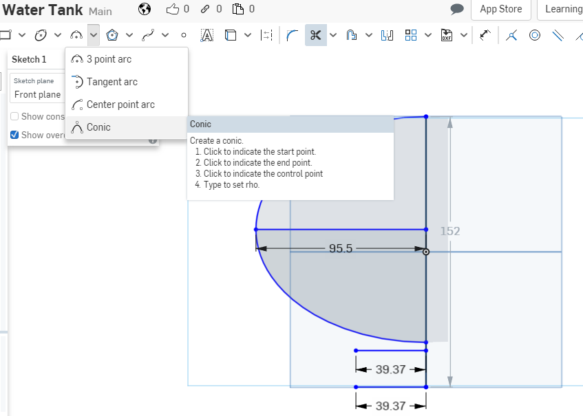
Now I am going to create a conic section to make a smooth transition to the base. The conic icon is shown in the picture (photo 11); you will have to use the pull-down to find the conic icon.
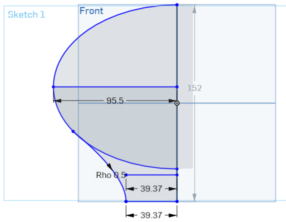
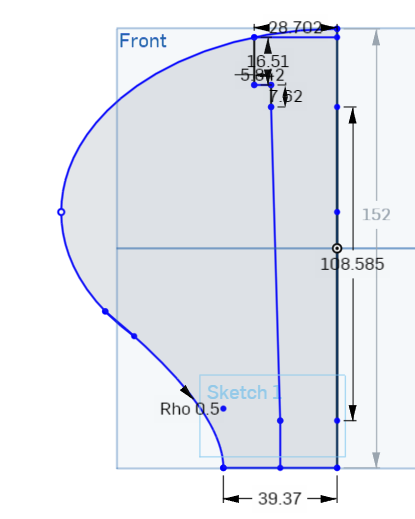
Here I created the conic section. I chose one point on the ellipse, the other at the bottom (39.37mm) and the control point at the other 39.37mm line near the middle. Next, I will cut away those lines that I do not need anymore (photo 12).
Here I have created the sprinkler outline (photo 13). Now I just cut away a couple of lines and I will be ready to revolve the sketch to make the final water tank.
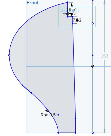
All the lines have been cutout to make a smooth revolve (photo 14).
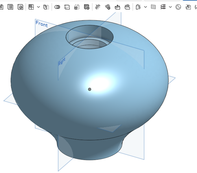
I covered the revolve function in the
first article on the water tower. To review, pick the revolve icon, then pick the line to revolve around, and the water tank should appear as shown in
photo 15.
It is just as easy as that. Don’t kid yourself, though. In this entire process I made mistakes that I had to correct, referring to the Internet several times to find out what was wrong, and I even had to refer a software bug to OnShape. So, it is not that easy. The whole process took me about four hours to do. I can do it faster now, but I had lots of practice while drawing the model.
Exporting an STL file To create the stl file, I am going to just repeat from last time. Now that we have the part, we want to export an *.stl file so the printer can print it out. At the bottom of the window you will see a tab called “Part Studio 1”. Right-click on the tab and you should get the following as shown in
Photo 16.
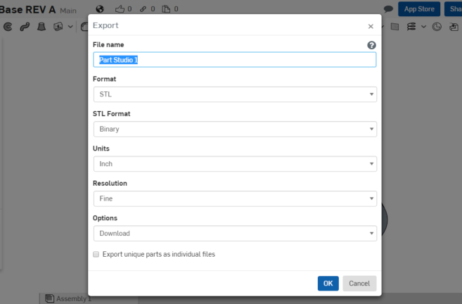
Left-click on “Export” on the pull-down list and the following should appear:
I typed in “Water Tank” as the file name. Make sure all other pull-down boxes are as shown. When you left click on “OK”, the stl file should download to your download folder. You can retrieve it from there.
Load into 3D printer
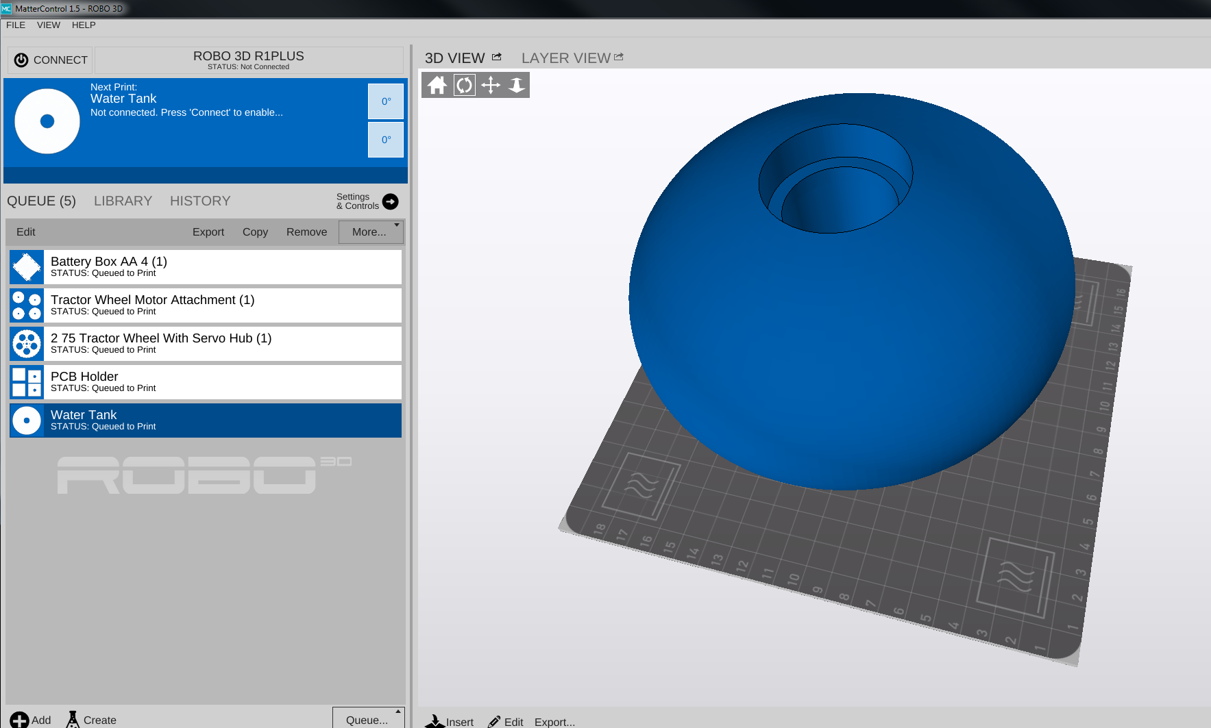
Following the instructions for your 3D printer, load the file that has been created. In my case that is “Water Tank.stl”. As you can see from the screen shot of my printer control software (Photo 17), it takes up just about the whole build plate. It is another very large part.
Print conditions I will be keeping the lab again at a constant 80°F, with the humidity between 10 and 40%. This is very important because you are going to spend a lot of time and some money printing just the base. It would be good to get it on the first try. I will be using white ABS, 1.75mm from MatterHackers.
Print
This is a large print. Should take about 24 hours to print out.
Print failure
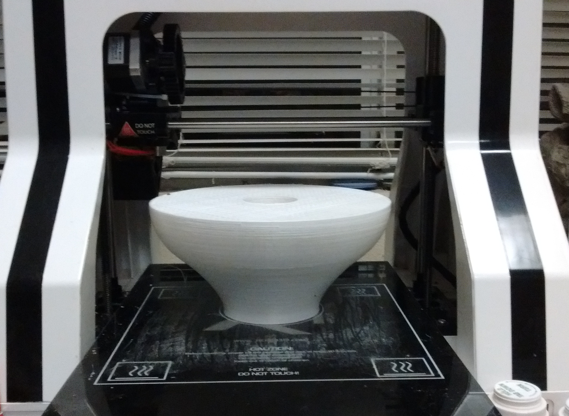
While this is a very large print, it takes many meters of material. I checked my spool of material and thought I had enough, but it turns out I did not. Here is what was printed out (Photo 18). It looks good, except for the missing top.
I need to order more material and start again. This is going to take a while, so look for the completion in the next blog.