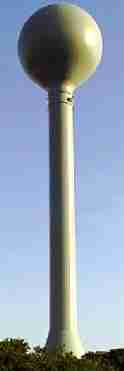
I was visiting Jerry Chapman at Split Jaw Products, Inc. several years ago and we discussed a unique project — a water tower that doubles as a garden sprinkler. I have been trying for years to figure out the limitations in making one and decided to give it a shot. Here is the first of a two-part series where I will use a new free CAD tool that is available to everyone, to build this structure.
NOTE TO READERS: Click on any photo to enlarge.

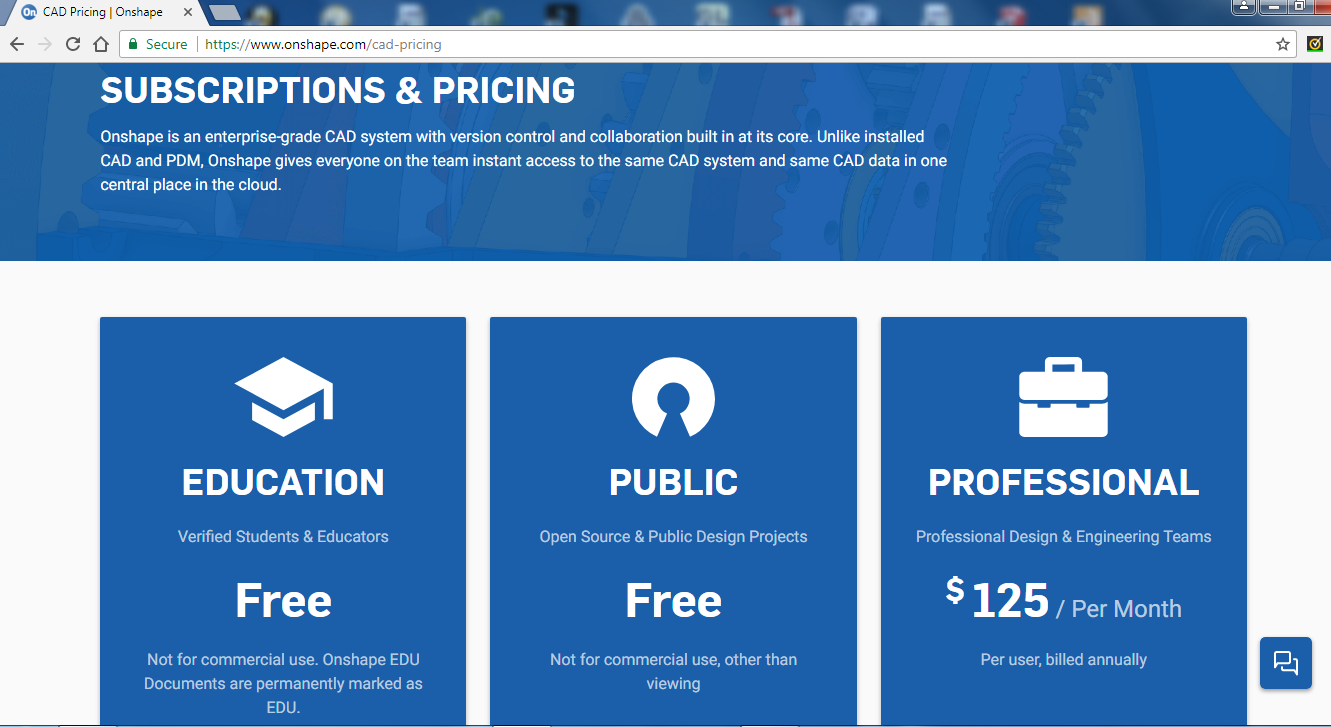
OnShape is a 3D CAD tool that is free to hobbyists. The people who helped develop the famous SolidWorks CAD tool decided to go off on their own and develop a new CAD tool that is like SolidWorks (https://www.onshape.com). You will have to register to use the product and the only possible downside is that if you use the free service, your files are shared amongst the community. If you want to keep your files hidden, you will have to upgrade to the professional package, which runs $125/month, billed annually.
You will need to subscribe to this service as shown in photo 3.
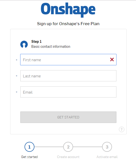
What is not shown in the above graphic is that below the Education, Public and Professional tabs there is a “Create Account” toggle. Educators will have to give information such as position, school, etc. Public is also free. Clicking on the Public “Create Account” tab, you will get the following, as shown in photo 4.
There are then a couple more steps to creating an account. I will not go through these here, as they are typical of creating web-based accounts.
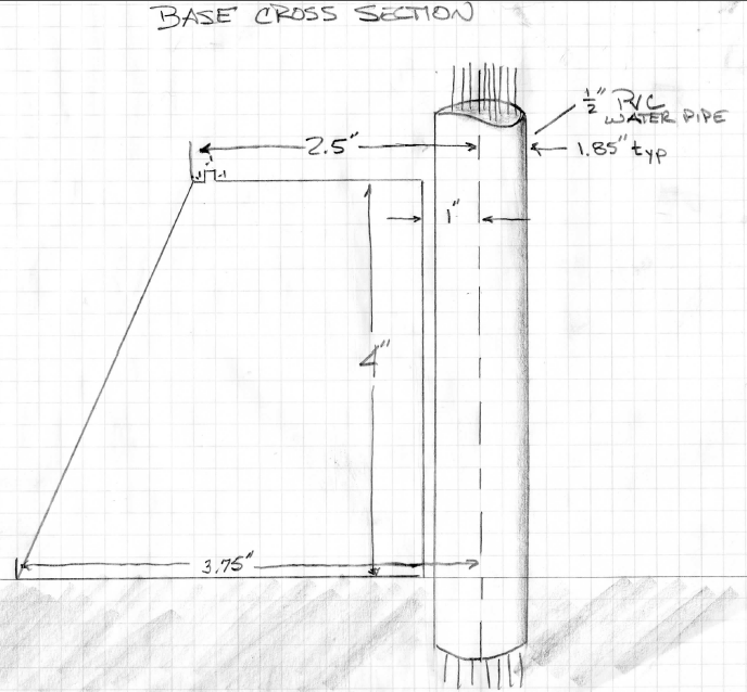
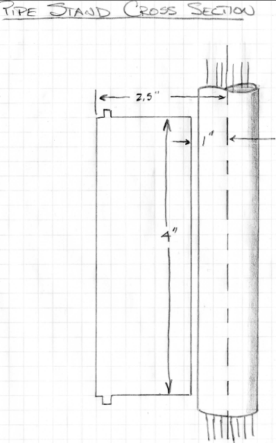
As always, I did some hand-drawn sketches (shown in photos 5 and 6) to get some idea of the design.
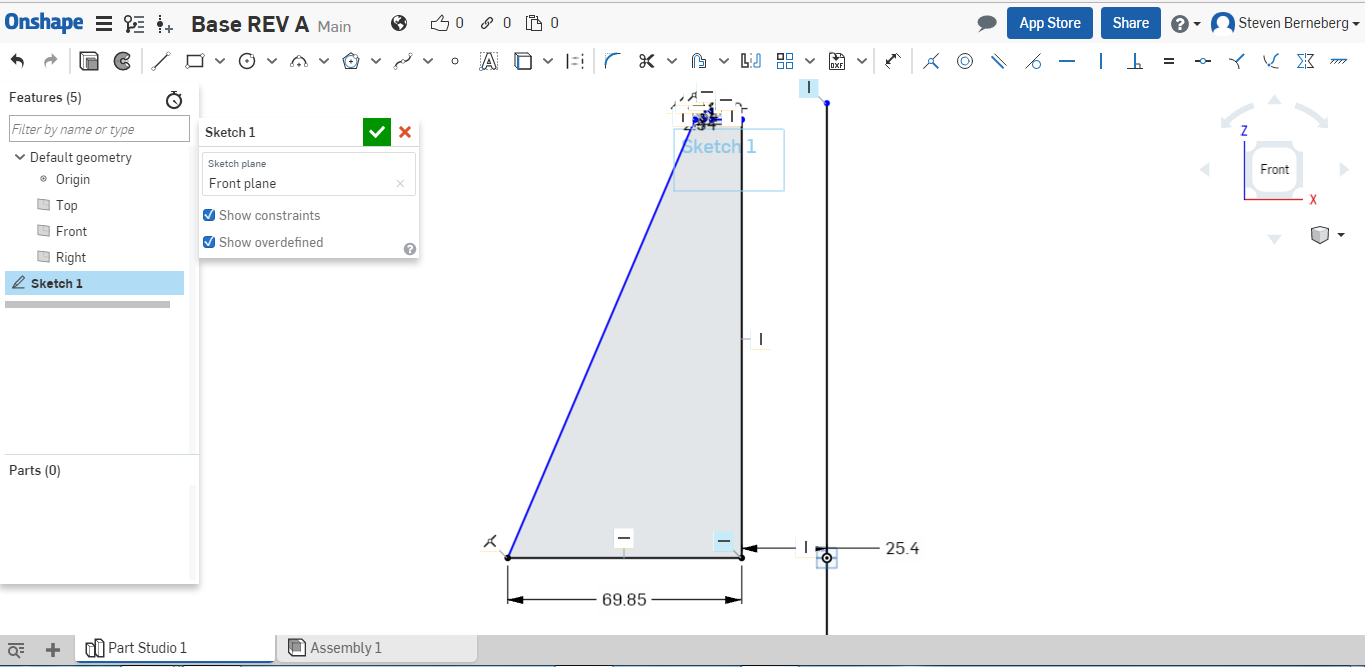
NOTE: We will be dealing with two different measuring units. While OnShape can use metric or imperial, the printer only uses metric. (There is an exception, but I will not get into it at this time.) My work-around is to use imperial measurements on my drawing and multiply them by 25.4, which is the conversion from inches to mm. You will see this during the drawing stage of developing the measurements on the drawing.
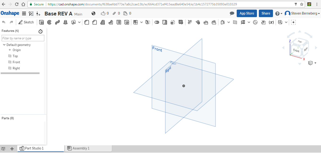
After you have created your OnShape account, you should see the following (photo 7):
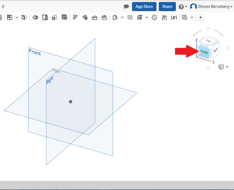
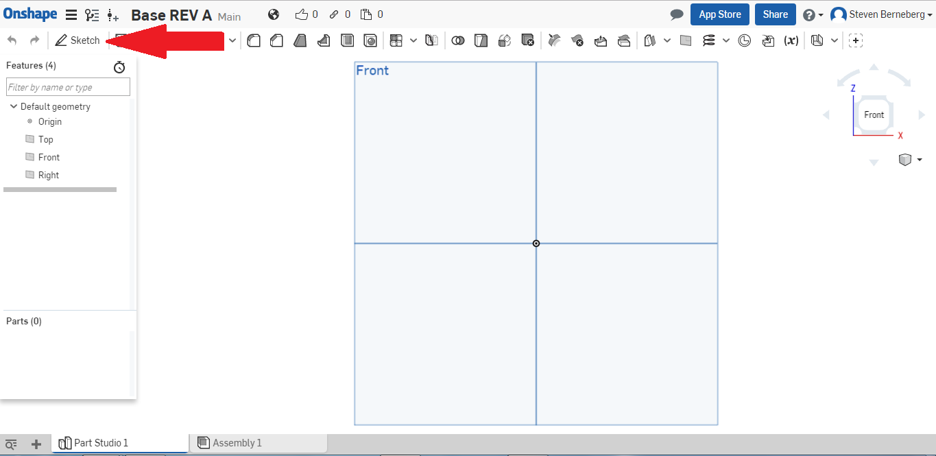
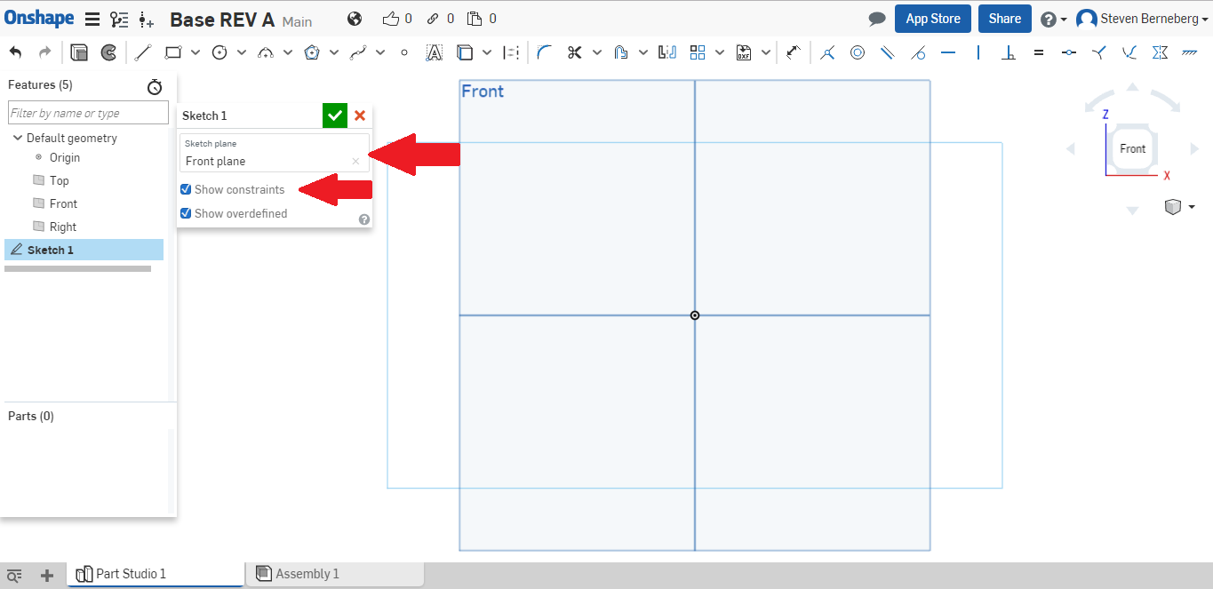
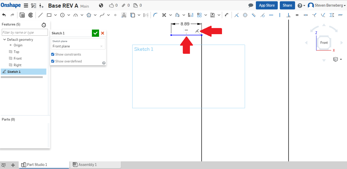
You will see a dialog box pop up. Click on the “sketch plane” (top red arrow in photo 10), then click on the Front plane. “Front Plane” should show up in the dialog box. Next, click the radio button for “Show constraints.” I will explain this latter on. You will also see in the far-left hand column (Features) that you have created “Sketch 1” and are ready to draw. In the upper toolbar, a series of icons show the drawing tools that are readily available.
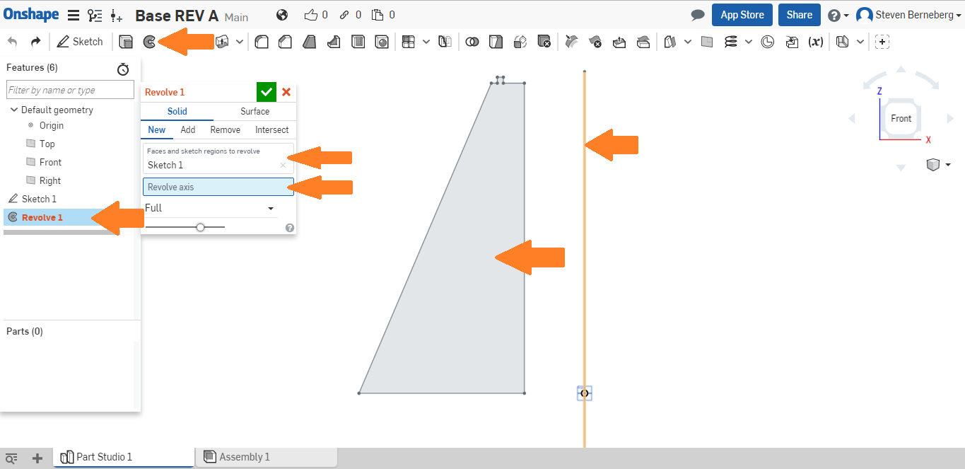
Click on that and you will see the balance of the screen as shown. Under the box “Faces and sketch regions to revolve” you should already see “Sketch 1.” The face that you need to revolve is the only one, so it is automatically selected. (Face is shown by the red arrow pointed to shaded area.) Next click on the box “Revolve axis,” then click on the baseline that we first created, which is pointed to by the far-right red arrow. Click on the green check mark in the box “Revolve 1” and you will see the completed part.
You will notice that nowhere will you find the floppy disk icon or a pull-down that says save. That is because every time you do something, it is automatically saved to the cloud. If you want to save it to your computer, you will have to upgrade to the professional version. Everything that you are putting in the cloud via this program is available to any subscriber of OnShape. Therefore, if you have something proprietary, the only way to protect it is to upgrade to the professional version. This is how the site makes money.
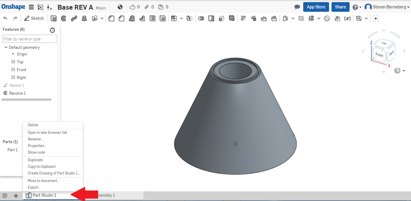
Now that you have the part, you need to export an *.stl file so the printer can print it. At the bottom of the window you will see a tab called “Part Studio 1.” Right-click on the tab and you should get the following shown in photo 16.
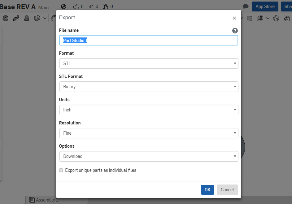
I typed in “Water Tower Base” as the file name. Make sure all other pull-down boxes are as shown. When you left-click on “OK” the .stl file should download to your download folder. You can retrieve it from there.
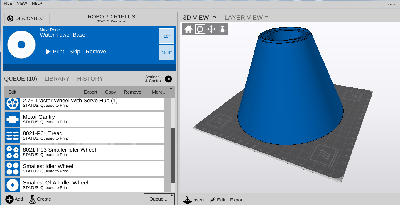
Following the instructions for your 3D printer, load the file that has been created. In my case, that is “Water Tower Base.stl”. As you can see from the screen shot of my printer control software in photo 18, it takes up just about the whole build plate, being a very large part — probably the largest part that I have printed with my machine.
A very large print requires the environment be a certain way to minimize warping and layer separation. I will be keeping the lab at a constant 80°F with the humidity between 10 and 40%. This is very important because you are going to spend a lot of time and some money printing just the base, so it would be good to get it right on the first try. I will be using white ABS, 1.75mm filament from MatterHackers. So here goes….
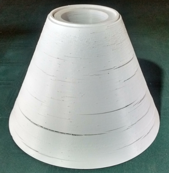
The print is so large that my printer software cannot output the statistics of the print. I had a feeling that it is going to take over 24 hours and about 35 meters of material. After many failed starts, my print is finally done. It took 25 hours and almost exactly 35 meters of material. There are several problems with the print that I need to address. One, the material warped over the period of the print, which created large cracks in the print. Two, the print started to separate from the print bed, so there is slight warping on the bottom. This I am not going to worry about; it will be surround by dirt and plant material, so will not be seen. The result is shown in photo 19.
My solution to all the cracks and warping: Bondo.
You have been introduced to a free on-line CAD program like SolidWorks. The base of the water tower used the “revolve” command, which can sometimes be intimidating. You can export an .STL file for 3D printing from this CAD program. Next time I will show you how the “extrude” command works to make the sections between the base and the top of the water tower.
The print did not come out perfect. That is not a surprise, as it is ABS material and subject to temperature fluctuations that will cause warping. Perhaps someone would like to try PLA and share with us how that came out? Until next time!